
Updated May 11, 2026
A strander tension monitoring system measures the tension of each individual strand on a cage or tubular strander to ensure balanced load distribution during cable manufacturing. In wire and cable manufacturing, strand geometry and mechanical balance start at the stranding process.
Whether you are running a cage strander, tubular strander, or cabler, consistent strand tension is one of the most important factors affecting product quality. If you’re exploring measurement technologies across the entire process, including extrusion, stranding, and quality control, our Wire & Cable Measurement Solutions guide provides a broader overview of available technologies.
Many production lines still rely on manual brake adjustment and total tension measurements at the take up. While this approach can work, it leaves a major blind spot in the process. Total tension does not reveal how load is distributed across each strand.
This is where modern telemetry systems such as the RTM (Rotating Telemetry Module) tension monitoring platform from FMS provide a significant advantage. By measuring tension on each individual strand directly on the rotating cage, engineers gain real insight into strand balance and process stability.
In this article we will look at:
• Why strand tension balance matters
• Limitations of traditional slip ring measurement systems
• How RTM wireless telemetry systems work
• When tension monitoring evolves into closed loop brake control

The FMS RTM tension monitoring and control platform.
The Hidden Problem with Total Tension Measurement
On many stranders, tension is measured only at the take up.
At first glance this seems reasonable. If total line tension looks correct, the process should be stable. In reality, this measurement does not reveal how load is distributed across individual strands.
Consider a cage strander with 18 payoff spools.
If total strand tension is measured at 90 N, there are many possible load distributions:
Example 1 (balanced)
Each strand carries 5 N.
Example 2 (imbalanced)
• 14 strands carry 4 N
• 4 strands carry 10 N
Both scenarios produce the same total tension reading. However the mechanical behavior of the strand bundle is very different.
When strand tensions are uneven, several problems can occur:
• Local strand elongation and neck down
• Concentricity variation in the finished cable
• Increased strand break risk
• Uneven load sharing during downstream processing
• Instability in compaction or extrusion operations
For process engineers, the real variable of interest is not total tension. It is strand to strand tension balance. Over time, these variations can show up as wider process distributions and lower capability scores. Engineers evaluating process stability often quantify this using capability metrics such as Cpk or Ppk. If you want to evaluate how measurement improvements affect capability, you can use our Process Capability Calculator for Cpk and Ppk.
Why Traditional Slip Ring Systems Struggle
Historically, monitoring individual strand tension on rotating machines required routing sensor signals through slip rings.
A slip ring is a rotary electrical connector that allows power and signals to pass between stationary and rotating machine components. While slip rings work well for power transmission, they present challenges for precision measurement signals.
Strain gauge based force sensors typically produce signals in the millivolt range. Small changes in electrical contact resistance inside a slip ring can introduce:
• Signal noise
• Measurement drift
• Offset errors
• Intermittent readings
Over time, brush wear, oxidation, and contamination can degrade signal quality. This is especially problematic when multiple sensors are routed through a high circuit count slip ring assembly.
As channel count increases, maintenance complexity also increases.
RTM Systems: Moving Measurement to the Rotating Frame
RTM systems solve this problem by changing where signal conditioning occurs.
Instead of transmitting millivolt signals through the slip ring, the measurement electronics are mounted directly on the rotating cage.
The process works like this:
- Each strand passes over a force measuring roller near the closing point.
- The force sensor signal is amplified and digitized locally on the rotating cage.
- Digital measurement data is transmitted wirelessly to a stationary receiver.
- The receiver communicates with the PLC or Control Center system.
Because the sensitive analog signal never leaves the rotating frame, measurement stability improves significantly.
This architecture also simplifies the rotating electrical system.
In many cases, the slip ring can be reduced to supplying only 24 VDC power. In some installations, the entire rotating telemetry system can even operate on battery power.
RTM IO vs RTM X42: Choosing the Right Architecture
The RTM platform includes two primary system configurations for strand tension monitoring.
RTM IO
RTM IO is designed for installations with up to about ten tension channels.
Key characteristics include:
• Wireless transmission from rotating cage to stationary receiver
• Analog outputs such as 0 to 10 V or 4 to 20 mA
• Direct connection to PLC analog input cards
This architecture works well when the goal is monitoring and trending strand tension.
It is often used for smaller stranders or retrofit applications where the PLC already expects analog inputs.

The RTM IO Telemetry System for Wire Tension Monitoring in Cage and Tubular Stranders
RTM X42
RTM X42 is a more advanced platform that supports up to 42 tension channels and communicates digitally via Ethernet and Modbus.
Key capabilities include:
• High channel count tension monitoring
• Digital communication with PLC or supervisory systems
• Integration with the RTM Control Center software
• Compatibility with automatic brake control systems
For larger cage stranders or plants interested in closed loop tension control, RTM X42 provides a scalable foundation.

The RTM X42 Wire tension monitoring system with Control Center and Brake Control
From Monitoring to Closed Loop Brake Control
Once individual strand tensions can be measured reliably, the next step is often automation.
Many cage stranders use rope or belt friction brakes on each cradle to regulate payoff tension. Traditionally, operators adjust these brakes manually during setup and occasionally during production.
However brake torque changes during a run as bobbin diameter decreases. This leads to gradual tension drift.
With RTM X42 systems, individual strand tensions can be used to automatically adjust each brake.
The process works as follows:
- Strand tension is measured on each wire.
- The Control Center compares actual tension to the target setpoint.
- Small adjustments are sent wirelessly to brake actuators mounted on each cradle.
- Brake torque is increased or decreased to maintain the target tension.
The result is a continuously balanced strand bundle throughout the entire payoff cycle.
For engineering managers focused on process stability and scrap reduction, this capability can significantly reduce operator intervention and improve product consistency.
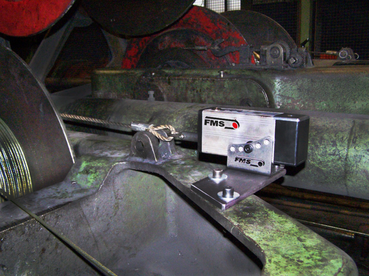
FMS brake actuator for automatic tension control installed on a strander.
Practical Benefits for Stranding Operations
For most plants, the value of RTM systems shows up in several areas.
Improved strand balance
Engineers gain visibility into how tension is distributed across the strand bundle. Problems that previously went undetected become immediately visible.
Reduced scrap and breakage
Balanced tension reduces localized overstressing of individual wires. For engineering managers evaluating upgrades to stranding equipment, the financial impact often comes down to scrap reduction, uptime improvements, and reduced troubleshooting time. If you want to estimate the potential impact for your own process, you can use our Wire & Cable Manufacturing ROI Calculator to model the cost savings associated with improved measurement and process control.
Better process stability
Closed loop brake control can compensate for bobbin diameter changes during long runs.
Reduced slip ring complexity
By removing sensitive analog signals from the slip ring, maintenance requirements often decrease.
Scalable architecture
RTM platforms can support both monitoring and control strategies as plant requirements evolve.
When Should a Stranding Line Consider Tension Telemetry?
Not every line needs advanced telemetry. However several situations make individual strand monitoring especially valuable:
• Cage stranders with more than 10 payoff spools
• Frequent strand break events
• Product concentricity or geometry challenges
• Long production runs with manual brake adjustment
• Aging slip ring systems causing signal reliability issues
In these environments, improving measurement visibility often leads directly to improved process control.
Final Thoughts
Stranding operations depend on mechanical balance across many rotating components. Without individual tension visibility, engineers are forced to rely on indirect indicators such as total tension or downstream quality results.
RTM wireless telemetry systems change that equation by allowing engineers to measure and understand strand behavior directly at the rotating cage.
For many plants, this additional insight is the first step toward more stable processes, reduced scrap, and improved product quality.
The technology discussed in this article is part of the RTM wireless telemetry platform from FMS, a manufacturer known for high precision force measurement and tension control systems used in wire, cable, converting, and industrial automation applications.
Gauge Advisor is the authorized Force Measuring Systems (FMS) sales partner for tension control and telemetry systems in the Western United States, supporting wire & cable plants with equipment selection, system integration, and technical application support.
If you’re evaluating a tension monitoring and control system for your cabeler or strander, request application guidance using the form below.

Founder, Gauge Advisor LLC
👉 Read these next:
Maximum Precision: Why FMS Force Sensors Outperform the Competition
Wire and Cable Measurement Solutions for Diameter, Coating, and Defect Detection