
Laser Micrometer Calibration Pin Calculator
Enter the outside-diameter (OD) range you measure. The tool builds a practical reference-size plan, can match it to LaserLinc catalog pin sizes, checks an optional list of standards you already have, and shows which LaserLinc micrometer models have a published range that covers the job.
- Inches or millimetersUse one working unit and see the converted equivalent automatically.
- Range coverageAdd an optional buffer and control the maximum planning ratio between sizes.
- Compare LaserLinc measurement rangesSee which models cover your diameter range, then confirm the remaining application requirements.
 Authorized LaserLinc sales & support partner. Gauge Advisor helps manufacturers select and quote micrometers, calibration kits, fixtures, software, integration, and complete measurement systems.

The standard is only one part of the result. Cleanliness, position, fixture, axis sequence, environment, software, and the approved procedure still matter.
Build a practical verification-pin plan
Use the output as a preliminary reference-size plan, then confirm the standards, uncertainty, procedure, and acceptance criteria required for your installed system.
Enter the dimensions
Use the smallest and largest outside diameters expected under the same verification plan. Add a buffer only when you intentionally want standards beyond those production limits.
Calculator loading. If this message remains, confirm that JavaScript is allowed for this page.
Before you use the results: Confirm the facility’s calibration procedure, uncertainty budget, acceptance criteria, calibration interval, traceability statement, validation plan, and compliance requirements against the installed micrometer configuration and approved quality documentation.
Calibration-planning disclaimer
This calculator is provided for preliminary informational and calibration-planning purposes. Final standard selection should consider the micrometer model and measurement window, required accuracy and repeatability, the standards’ certified values and uncertainty, environmental conditions, fixture and handling effects, software configuration, customer requirements, and the facility’s approved measurement-management procedure. Availability and certification should be confirmed before purchase or use.
Proprietary tool notice
© 2026 Gauge Advisor LLC. This calculator, including its source code, selection workflow, unit conversion, range-fit logic, written content, interface, and output presentation, is protected by applicable U.S. copyright law. Unauthorized copying, republication, automated extraction, reverse engineering, removal of attribution, or use to create a competing commercial tool is prohibited without prior written permission. Use is also subject to the Gauge Advisor Terms of Use.
Coverage first, then the controlled measurement method
The calculator checks size coverage. Your approved metrology procedure determines how to use the calibration standards and document the measurement results.
Define the working OD range
Start with the smallest and largest products that will use the same gauge configuration and verification plan. Add a buffer only when it reflects a real coverage need.
Choose the spacing between reference sizes
A smaller adjacent-size ratio produces more theoretical reference points. The selected ratio is a planning preference, not a manufacturer or standards-body requirement.
Confirm real standards and procedure
Match the plan to standards with suitable certified values and uncertainty, then use the approved fixture, position, axis sequence, environment, software, and acceptance rule.

- Traceability and accuracy answer different questions. Metrological traceability belongs to a documented measurement result and calibration chain with contributing uncertainties.
- Investigate before adjusting. Control the standard, units, fixture, position, axis, environment, recipe, and repeat sequence before deciding the system needs a change.
- Treat range fit as the first model screen. Axis count, part shape, accuracy, repeatability, speed, product presentation, fixturing, and data collection and reporting complete the selection.
Does the system meet a defined requirement now?
Compare one or more known standards using a controlled method and documented acceptance rule. Routine verification does not necessarily change the instrument.
What is the relationship between indication and reference?
A documented calibration establishes measurement results and associated uncertainty over defined conditions and a defined range. It may identify bias without changing the system.
Should the system be changed?
Adjustment alters the system to reduce error. It should be controlled, authorized, and followed by verification—not used to hide an unresolved presentation or environmental problem.
Build the LaserLinc configuration around the product
LaserLinc supplies calibration kits as part of an integrated measurement approach, but the complete system also includes the right micrometer axes, measurement window, guides or fixtures, operator interface, data handling, and support.

Triton laser micrometers
Three simultaneous axes in a fixed-axis laser micrometer provide more views for measuring average diameter and estimating ovality on round and elliptical products.
- Strong fit
- Round tubing, wire, cable, hose, and other orientation-sensitive profiles
- Review
- OD range, tolerance, speed, motion, transparency, guide location, software, and control needs
- Verify
- Use standards and a presentation method suitable for every active measurement axis
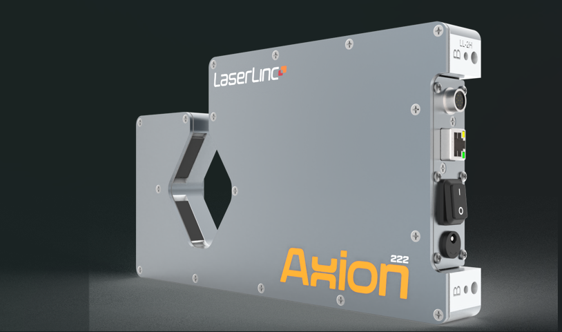
Axion laser micrometers
Single- and dual-axis models provide application-specific measurement for round and non-round profiles, hot products, constrained installations, and multi-strand work.
- Strong fit
- Width, height, rectangular profiles, basic OD, hot products, split-head layouts, and value-focused systems
- Review
- Axis geometry, field access, profile orientation, measurement window, accuracy, and integration
- Verify
- Confirm the standard’s position and the intended axis or axes before comparing results
Plan reference coverage around the real manufacturing task
The same calculator can support very different measurement methods. The part state and decision being made are as important as the diameter range.
Tight OD and ovality verification
Plan standards near catheter, guidewire, cannula, tubing, mandrel, or shaft diameters, then validate the complete fixture, axis sequence, software, and quality record.
Explore medical measurement systemsCover multiple production sizes
Define the actual product family rather than calibrating around one convenient pin while the line runs a much wider range of bare, coated, or jacketed diameters.
Explore wire & cable measurementSeparate the gauge from the product
A controlled reference can help determine whether a disagreement begins with the product, presentation, environment, gauge, software, or comparison method.
Review offline and inline gauge optionsSend enough information to make the next answer useful
A drawing is helpful but not required. A short description of the installed system, OD range, tolerance, and verification goal is enough to begin.
- 01Gauge identity
LaserLinc model, serial number, axis count, controller or processor, software, and whether the system is inline or offline.
- 02Product range
Minimum and maximum OD, nominal sizes, tolerances, material, shape, transparency, line speed, and product motion.
- 03Reference requirements
Desired sizes, certificate or traceability requirements, available standards, uncertainty needs, and current acceptance criteria.
- 04Presentation method
Fixture, guide, V-block, stand, field position, axis sequence, rotation, handling, and environmental conditions.
- 05Data collection and reporting
Local display, Total Vu, SmartLinc, saved results, reports, SPC, PLC communications, alarms, or process control.
- 06Decision and timing
New system, replacement, verification failure, audit preparation, qualification, upgrade, budgetary quote, or active production problem.
Related Gauge Advisor tools and guides
Continue from the pin plan into model selection, troubleshooting, fixturing, and the application-specific measurement procedure.
Laser micrometer calibration-pin questions
Does this calculator perform a laser micrometer calibration?
No. It plans reference sizes across a working OD range. Calibration requires a documented method, suitable standards, controlled conditions, measurement results, uncertainty, acceptance criteria, records, and the approved response to an out-of-tolerance result.
Is the 4× spacing option a LaserLinc, ISO, ASTM, or NIST rule?
No. It is the widest spacing guideline offered by this tool. Select 1.5×, 2×, or 3× when you want a denser theoretical set. The facility’s approved procedure and the installed system determine the actual standards and calibration method.
Does a NIST-traceable pin make the micrometer or result NIST traceable?
No. Metrological traceability is a property of a measurement result supported by a documented, unbroken calibration chain in which each link contributes uncertainty. A certified standard is important, but the complete measurement method and records still matter.
Why should I use more than one reference size?
Multiple standards let the approved procedure evaluate system behavior at more than one point in the working range. The exact number and sizes depend on the range, target sizes, required uncertainty, micrometer configuration, risk, and quality-system requirements.
What does the LaserLinc catalog-pin option do?
It converts the theoretical coverage plan into a preliminary set drawn from the LaserLinc reference-pin size list maintained by Gauge Advisor for quoting. It rounds the lower and upper coverage boundaries outward when catalog sizes allow and adds intermediate pins as needed for the selected planning ratio. Gauge Advisor confirms current availability, certified value, grade/class, material, certificate options, and kit compatibility before order.
Can I enter the calibration pins my facility already owns?
Yes. Open the advanced section, enable the available-standard comparison, and enter the diameters in the selected unit. The tool will test coverage and the selected planning ratio. It does not assess the standards’ condition, certificate, uncertainty, class, or suitability.
Does a LaserLinc model shown in the result automatically fit my application?
No. The dynamic model screen checks only whether the buffered OD range falls within a published measurement window. Axis count, part shape, accuracy, repeatability, speed, product presentation, transparency, fixturing, environment, software, data, and control requirements still need review.
Can Gauge Advisor help source LaserLinc calibration kits or pins?
Yes. Gauge Advisor can coordinate a LaserLinc calibration-kit or reference-standard review and confirm the exact model, size, documentation, and availability before quotation. Include the gauge model, serial number, working OD range, tolerance, and certificate requirements.
How often should a laser micrometer be calibrated or verified?
There is no universal interval for every application. The facility should set calibration and intermediate-verification intervals using risk, use frequency, environment, history, customer requirements, maintenance, quality procedures, and the consequence of an incorrect result.
Technical basis and current manufacturer sources
- LaserLinc — Laser Micrometers. Current measurement scope, inline/offline positioning, Axion and Triton models, SmartLinc integration, and published warranty positioning.
- LaserLinc — Triton. Three-axis measurement, round and elliptical product positioning, average diameter, estimated ovality, accessories, and Total Vu integration.
- LaserLinc — Axion. One- and two-axis positioning for rectangular profiles, hot products, constrained installations, and multi-strand applications.
- LaserLinc — Current Laser Micrometer Datasheet. Published model measurement windows used by the calculator’s preliminary range-only screen.
- LaserLinc — Integrated Solutions. Calibration kits, guides, stands, stations, software, and integrated measurement-system context.
- LaserLinc — Warranty and Service. Typical four-year micrometer and accessory coverage plus published phone, email, and interactive support terms.
- NIST — Metrological Traceability. Traceability as a property of a measurement result supported by a documented calibration chain and contributing uncertainties.