Film or sheet
One continuous web at the entered finished thickness and width.
A = thickness × width
Calculate nominal output from line speed, or find the line speed needed for a target output. Choose film, sheet, blown film, tubing, wire and cable coating, rod, strand or a custom profile.

Mass rate = polymer area × line speed × matching density. Use the result to review whether the complete line can feed, stabilize, cool, measure and control that rate.
Use dimensions, speed, and density that describe the same product state and measurement location. Finished/cooled dimensions normally pair with finished or apparent product density—not melt density or loose pellet bulk density.
Example values are loaded so the result is visible immediately. Replace them with your process values and review the assumptions beside the result.
Calculator loading. If this message remains, confirm that JavaScript is allowed on this page.
Example loaded: one 50 µm × 1,000 mm flat web at 30 m/min and 0.92 g/cm³.
The formula is simple. Choosing the correct area and density basis is what makes the answer useful.
One continuous web at the entered finished thickness and width.
A = thickness × widthTwo film plies at the entered single-wall thickness and layflat width.
A ≈ 2 × t × layflatPolymer between the finished outside and inferred inside diameters.
A = π/4 × (OD² − ID²)Only the polymer between the finished OD and core/previous-layer OD.
A = π/4 × (OD² − core²)One solid circular output, multiplied by the number of identical strands.
A = π × D² / 4Actual polymer-only area after excluding holes, lumens, substrates, and conductors.
A = entered polymer areaFinished product dimensions and takeoff speed should normally use finished or apparent product density. Melt density is appropriate only when the area and average velocity are also evaluated in the melt state.
That distinction matters. Mixing melt density with cooled downstream dimensions can materially understate the calculated rate.

This calculation establishes a nominal target. A gravimetric extrusion weigh hopper measures actual lb/hr or kg/hr on the operating line and can support closed-loop throughput control. Gauge Advisor supplies represented measurement and process equipment and can help select and quote the appropriate system. Use the calculated rate with actual line data to identify whether measurement, material feeding, melt delivery or another process constraint needs review.
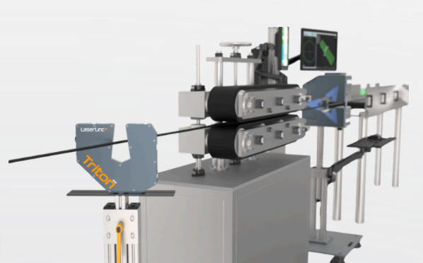
Coordinate the rate with the resin, melt, dimensional, wall, web, and process variables that determine the finished product.

MAAG pumping and filtration can address pressure stability, screen-change continuity, melt quality, and downstream consistency.
Review polymer processing solutions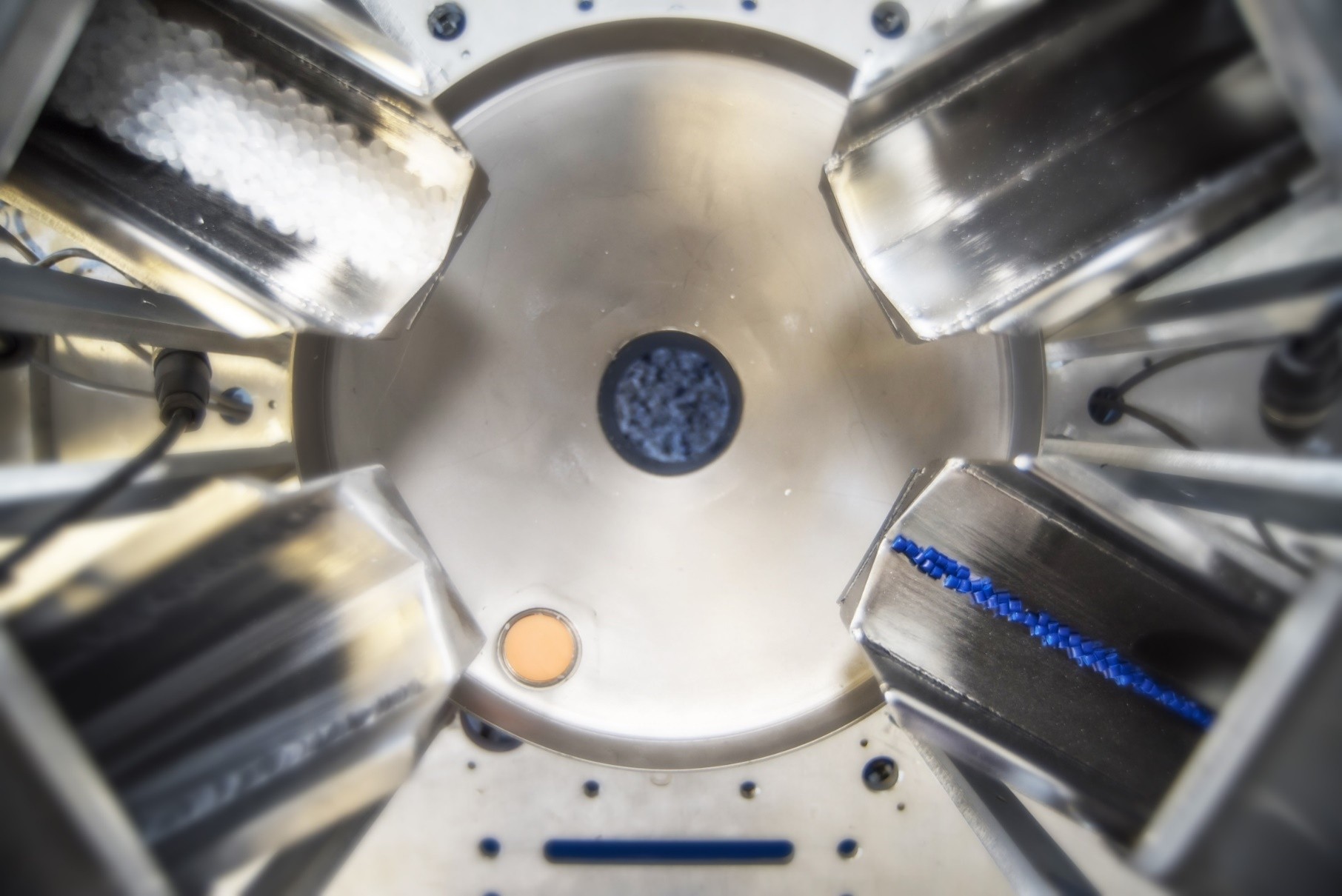
ABS material-handling systems coordinate resin supply, recipe accuracy, drying, receivers, controls, and plant expansion.
Explore resin handling systems
Addex air rings, intensive cooling, and gauge-control technologies help turn nominal output goals into a stable blown-film process.
Use the air-ring selectorThe calculator carries the product geometry, density basis, production result, and review notes into an editable request. Add a line drawing, material data sheet, and representative production result when available.
Use the tool that matches the part of the process you need to check next.
The tool makes the mass-balance basis transparent while keeping equipment selection and process capability tied to the complete application.
Yes. Select “I know throughput,” enter the target mass rate, geometry, product count, and matching density, and the calculator solves the required nominal line speed. That speed still has to be checked against extrusion, cooling, haul-off, winding, tension, and quality limits.
Use the density that matches the state and location of the entered geometry and velocity. Finished/cooled dimensions and takeoff speed normally use finished or apparent product density. Melt density is appropriate only with melt-state area and velocity. Loose pellet bulk density is not appropriate for this mass-balance calculation.
For a simple collapsed blown-film tube, polymer area is approximately two times single-wall thickness times layflat width because the collapsed tube has two plies. For gusseted or complex structures, use the total developed width or enter a verified custom polymer area.
Tubing uses the annular area between finished OD and an ID inferred from wall thickness. Wire and cable mode uses the annular area between finished coated OD and the core or previous-layer OD, so its mass result represents polymer jacket or coating only.
Yes. Enter one representative product geometry and use the identical-product count to multiply its area. All repeated outputs must run at the same entered speed and use the same density. Mixed sizes or materials should be calculated separately and summed.
Actual net and gross output can differ because of trim, startup loss, scrap, recycle, drawdown, die swell, shrinkage, speed slip, dimensional variation, fillers, foaming, multilayer construction, moisture, and the measurement location. Validate important targets against representative measured mass flow.
No. Throughput is an important input, but equipment selection also depends on polymer rheology, temperature, pressure, viscosity, contamination, filtration area, residence time, drive speed, die and screw behavior, cooling, controls, and operating margin.
No. It is a geometry-based planning estimate. A representative gravimetric, loss-in-weight, weigh-bin, or timed mass measurement is the better way to validate actual production output and reconcile gross extruder flow with net saleable product.
This calculator is provided for preliminary informational, educational, and extrusion-production planning. It uses cross-sectional geometry, line speed, density, and an identical-product multiplier to estimate a nominal mass rate or required line speed. It does not establish actual equipment capacity or guaranteed production.
Results can be affected by density basis, fillers, foaming, multilayer construction, voids, dimensional tolerance, drawdown, swell, shrinkage, trim, speed slip, recycle, scrap, downtime, and measurement location. It does not confirm extruder, die, melt-pump, filtration, cooling, haul-off, winding, tension-control, or material-handling capability.
© 2026 Gauge Advisor LLC. Gauge Advisor's original calculator source code, geometry workflow, explanatory content, interface, result presentation, and secure transfer of results to the inquiry form are protected by applicable law and the Gauge Advisor Terms of Use.
Manufacturer names, product names, specifications, trademarks, and literature remain the property of their respective owners. Confirm final equipment and performance with current manufacturer information and application review.
© 2026 Gauge Advisor LLC. Geometry-based extrusion production-planning tool.