Geometry screen
The tool checks the full entered OD and wall envelope against each of six model-and-frequency rows. It never combines HF and LF limits to manufacture a larger range.

See which current LaserLinc UltraGauge configurations contain your tubing range, compare inline and benchtop paths, and carry the result into a quote or representative sample test.
 Authorized LaserLinc sales & applications support partner. Gauge Advisor coordinates transducer review, sample testing, tanks, guiding, AutoPilot, Total Vu, laser OD measurement, and complete system quotations.
Geometry narrows the field; representative samples confirm the answer. Material response, waveform quality, coupling, alignment, speed, and the required uncertainty still determine the final transducers and setup.
Enter one product-family envelope at a time. The selector checks the complete OD and wall range against each individual model-and-frequency row, then builds the appropriate LaserLinc system-review path.
Use the minimum and maximum OD and wall values that one sensor configuration must cover. For unrelated product families, run a separate result for each.
Selector loading. If this message remains, confirm that JavaScript is allowed for this page.
What this screen can tell you: whether one current published model-and-frequency row covers the entered OD and wall envelope. It cannot confirm acoustic response, echo separation, uncertainty, repeatability, tank fit, guiding, or final transducer style without representative parts and the intended process conditions.
Published wall ranges are approximate and depend on material properties, acoustic impedance, frequency, transducer style, and sometimes orientation. Actual performance can also be affected by grade, additives, reinforcement, layers, surface finish, curvature, temperature, water quality, bubbles, alignment, centering, line motion, tank geometry, calibration, waveform settings, and the required measurement uncertainty. Final transducers, channel layout, frequency, tank, guiding, calibration, software, and capability must be confirmed with representative samples and the current manufacturer documentation.
© 2026 Gauge Advisor LLC. This selector’s original range-evaluation logic, unit handling, workflow questions, customer-facing result presentation, and contact handoff are protected content. Unauthorized copying, republication, scraping, reverse engineering, automated extraction, removal of attribution, or use to create a competing commercial tool is prohibited without written permission. LaserLinc names, specifications, trademarks, and manufacturer materials remain the property of LaserLinc, Inc.
The published range is the first filter. Acoustic behavior and the complete system architecture determine whether the application becomes a stable production or QA method.
The tool checks the full entered OD and wall envelope against each of six model-and-frequency rows. It never combines HF and LF limits to manufacture a larger range.
Representative samples confirm signal strength, echo separation, material velocity, attenuation, layer visibility, surface effects, and the most useful frequency and transducer style.
The final review adds the correct tank or bench fixture, guiding, channel count, manual or automatic positioning, laser OD measurement, Total Vu workflow, communications, and validation plan.
These are the February 2026 LaserLinc datasheet ranges used by the selector. High frequency is 30–50 MHz; low frequency is 2.25–20 MHz.
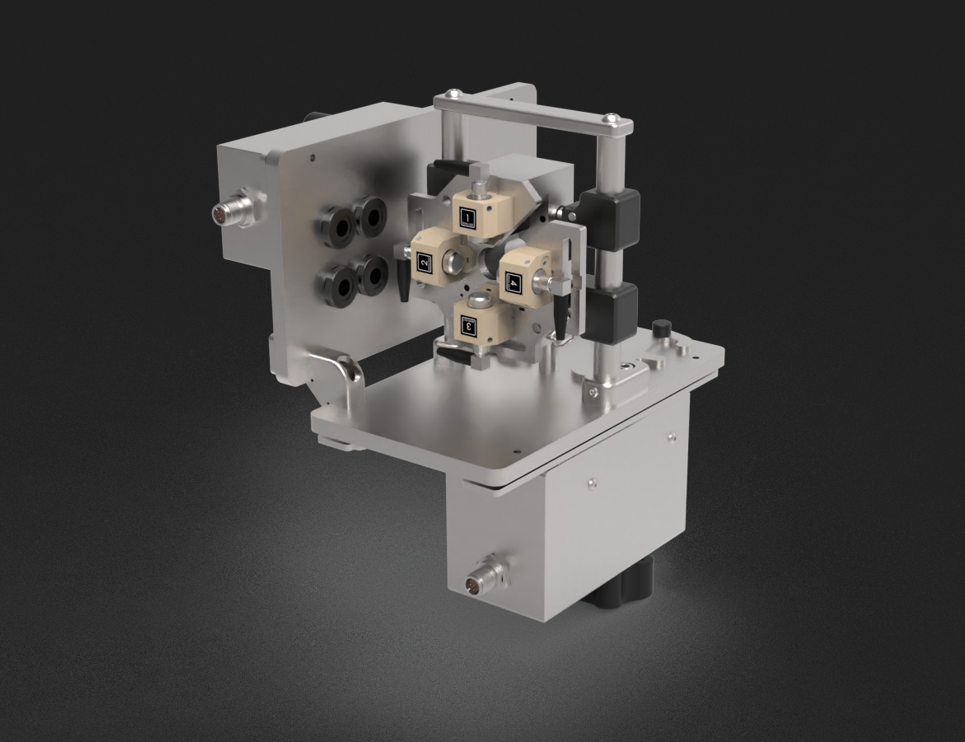
Compact starting assembly for smaller tubing ranges.
Broader small-to-medium tubing coverage.
Large-range, multi-channel sensor-assembly family.
The bracketed inch values are calculated equivalents of the canonical metric limits used by the selector. The manufacturer’s printed inch values are more broadly rounded; internal unit changes retain the unrounded metric value.
Gauge Advisor can coordinate the measurement head, positioning, offline verification, OD layer, software, communication, and process-control scope as one LaserLinc system.

Continual direct wall-path measurement and wall-distribution insight for suitable tubing and extrusion applications.
Review LaserLinc ultrasonics →
Automatically positions compatible UltraGauge assemblies to reduce repeated manual alignment during startup and product changeovers.
Explore inline wall measurement →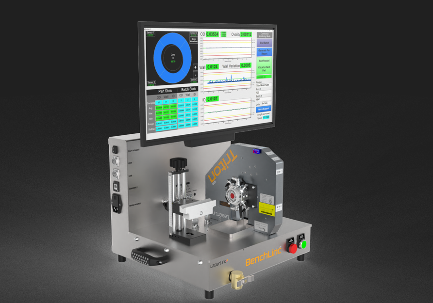
Controlled benchtop wall and concentricity inspection for suitable rigid, metallic, or cut-to-length tubing.
Review sample inspection →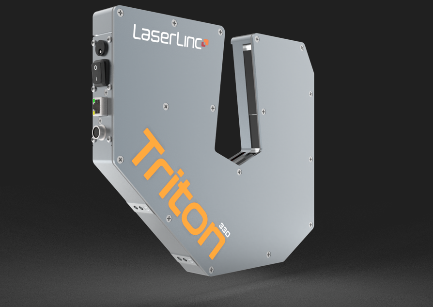
Coordinate direct laser OD and ovality with ultrasonic wall data when the process needs a complete cross-section and calculated ID.
Compare LaserLinc micrometers →
Fully customizable—not a black box. LaserLinc can tailor the application to your process at no charge, or a technically capable customer can configure the workflow directly.
Explore Total Vu →Combining the right measurement layers turns separate sensor readings into a useful cross-section, quality record, and process-control workflow.
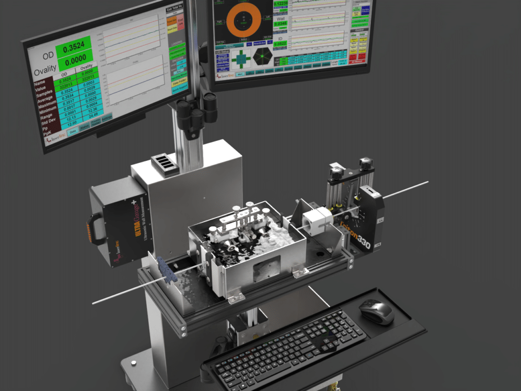
UltraGauge resolves configured wall-thickness paths from ultrasonic echoes at the material interfaces.
Configured wall paths show how material is distributed around the tube and support concentricity or eccentricity calculations.
A synchronized Axion or Triton laser micrometer adds direct outside-diameter data; Triton adds three-axis ovality visibility for round and elliptical products.
ID is calculated from coordinated measured OD and wall data. The selector’s entered-limit ID envelope is planning math, not a direct lumen measurement.
A published geometry match is useful, but the waveform decides whether the application is stable enough for the required production or quality method. This is especially important for metals, very thin walls, multilayer products, filled compounds, and unusual surfaces.
The same range table can lead to different systems depending on material, handling, and whether the part is being produced continuously or inspected after manufacture.
Inline wall distribution and concentricity for suitable catheter, tubing, balloon, and micro-extrusion applications, often paired with laser OD and Total Vu.
High-frequency geometry screening for suitable NiTi, stainless, or specialty tubes, with representative sample correlation and controlled alignment as core steps.
Insulation or jacket wall and concentricity review where the conductor, core construction, material interfaces, coupling, and product presentation support stable ultrasonic echoes.
Layers may be measurable when their acoustic interfaces are distinct enough to resolve. Samples determine which interfaces, frequencies, and transducer arrangements are practical.
Move from the range screen into wall-measurement architecture, metallic-tubing feasibility, alignment, validation, or the broader medical and wire measurement workflow.
No. It confirms only that the entered OD and wall envelope fits one current published model-and-frequency row. Representative samples, material response, waveform quality, coupling, alignment, tank geometry, process conditions, and the required uncertainty determine final feasibility.
The current datasheet defines high frequency as 30–50 MHz and low frequency as 2.25–20 MHz. Higher frequencies are often useful for thin-wall resolution, while lower frequencies can support thicker walls and different penetration needs. When both rows fit the geometry, the sample waveform determines the better path.
UltraGauge directly resolves ultrasonic wall paths. A production ID result is calculated from synchronized OD and wall data; add a LaserLinc laser micrometer when direct OD, ovality, and calculated ID are required. The selector’s ID envelope is planning math from the entered limits, not a direct lumen measurement.
That is an application-review result, not an automatic no. LaserLinc can review representative samples, a split recipe or sensor strategy, an application-specific arrangement, or whether the range should be divided into separate product families.
LaserLinc publishes a demonstrated wall example of approximately 0.003 in [75–76 µm] for metal NiTi/Nitinol tubing. Actual metallic performance depends on grade, surface, geometry, frequency, transducer style, alignment, and the required repeatability. Values below that example should be sample-tested rather than treated as a definitive no.
BenchLinc UT is the natural starting path for suitable rigid, metallic, cut-to-length, or finished tubing that will be inspected offline. Continuous extrusion feedback points toward inline UltraGauge; applications that need production monitoring plus independent sample verification may use both.
AutoPilot automatically positions compatible UltraGauge sensor assemblies, reducing repeated manual alignment during startup and product changeovers. It is especially useful when a line runs many recipes, several shifts, or frequent setups.
The current datasheet lists four measurement points for UG412 and UG430 and four to eight for UG460. Final channel count, transducer arrangement, orientation, processor, and reported dimensions are configuration-specific and require application review.
LaserLinc’s current warranty page lists UltraGauge products, except transducers, at four years and UltraGauge transducers at one year. LaserLinc also publishes phone and remote engineering support during business hours; application, installation, training, on-site, and upgrade scope should be confirmed with the quotation.