Prepare & deliver resin
Move the intended material to the intended line, condition it when necessary, and meter the recipe consistently.
Resin handling systems →
Connect the parts of the line that influence finished dimensions: move and meter the material, stabilize and filter the melt, then measure pipe OD, profile width and height, ovality, wall thickness, and concentricity with the right technology.
Choose the area closest to the problem or planned upgrade. The Pipe & Profile Extrusion System Selector will open the relevant questions here and keep every process path in one experience. Switch paths at any time; if the issue crosses stages, review another area or request a full-line application review.
The relevant questions will open here as part of the same Pipe & Profile Extrusion System Selector. Results are preliminary starting paths—not final equipment sizing.
Coordinate conveying, blending, drying, storage, routing, controls and qualified regrind or powder handling as one connected system.
This material-handling question path could not load here.
Continue in full-screen view →Match contamination severity, polymer, required fineness, throughput, changeover tolerance and operator involvement to the right starting architecture.
This filtration question path could not load here.
Continue in full-screen view →Use material, application, pressure severity and throughput to identify the preliminary family. Final pump size still requires viscosity, inlet and outlet pressure, temperature and operating data.
This melt-pumping question path could not load here.
Continue in full-screen view →Round pipe uses the established round-product logic for OD, ovality, wall, concentricity and calculated ID. The profile branch adds one projected dimension, dual-axis width and height, and a clear application-review path for complex contours.
This measurement question path could not load here.
Continue in full-screen view →A dimensional problem found at the end of the line may have started with recipe variation, interrupted material delivery, screen loading, melt-pressure movement, die behavior, cooling, calibration or haul-off. Start where the first unstable variable appears.
Move the intended material to the intended line, condition it when necessary, and meter the recipe consistently.
Resin handling systems →Select manual, continuous or self-cleaning filtration around contamination, uptime and pressure response.
Melt filtration systems →Use an application-matched gear pump where stable downstream pressure and metered flow address the actual bottleneck.
Pipe/profile melt guide →Monitor the outside dimensions that matter and add ultrasonic wall measurement when the material and range support it.
LaserLinc measurement →Common sequence, not a universal layout: filtration is often upstream of the melt pump to protect the pump and die, but polymer, contamination, residence time, pressure limits and equipment design determine the final arrangement. Not every line needs every stage shown.
Axis count is an engineering choice—not a quality ranking. Choose it from the product geometry, the dimensions that drive the process decision, how the product moves, and the complete hot-to-cold size envelope.
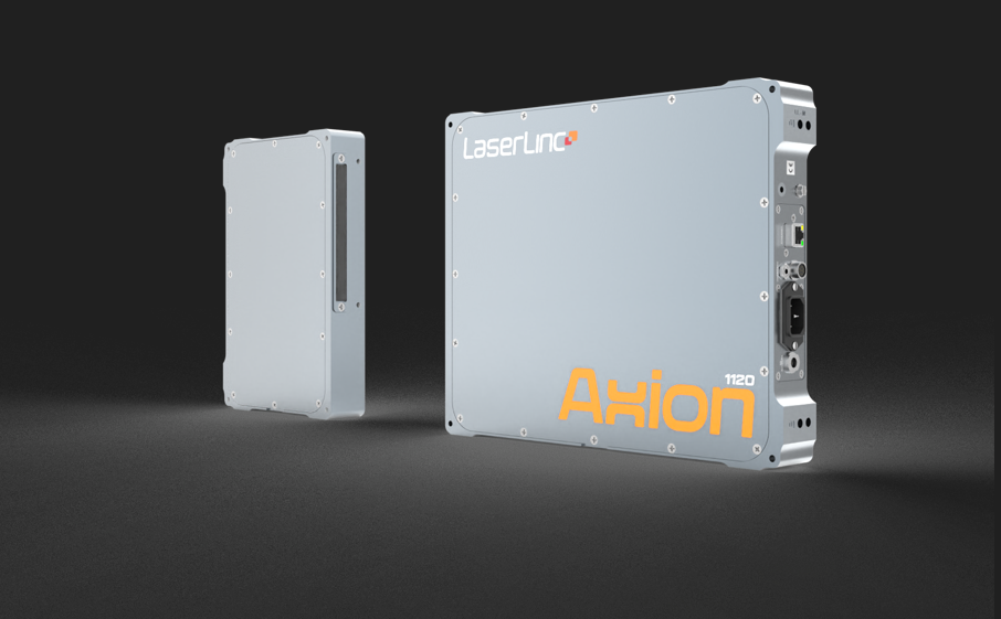
Use when one OD, width or height is the actual requirement, or when a split transmitter/receiver arrangement supports a constrained installation.
Current published single-axis family reaches 231 mm measurement range. Final usable opening and wander allowance require review.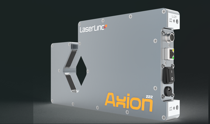
Two perpendicular axes measure simultaneous projected dimensions. For qualified profiles, that commonly means width and height—not a complete contour reconstruction.
Current published dual-axis family reaches 114 mm measurement range. Twist, sag and orientation remain application variables.
Three simultaneous views provide the strongest current fixed-axis LaserLinc path for average OD and estimated ovality on moving round or elliptical pipe.
Current published triple-axis family reaches 52.6 mm measurement range. Fixed views do not create a complete roundness map.
UltraGauge directly measures wall distribution on acoustically suitable products. Add laser OD when coordinated outside dimensions and calculated ID are required.
Current published assemblies reach 60 mm OD. Material response, coupling, alignment and representative samples determine feasibility.Put the readings to work. Total Vu software gives your team customizable live views, saved measurements, reports and optional process control for your pipe or profile line. If your machine already handles the display and records, SmartLinc Processor can send laser micrometer measurement tags to its PLC or HMI.
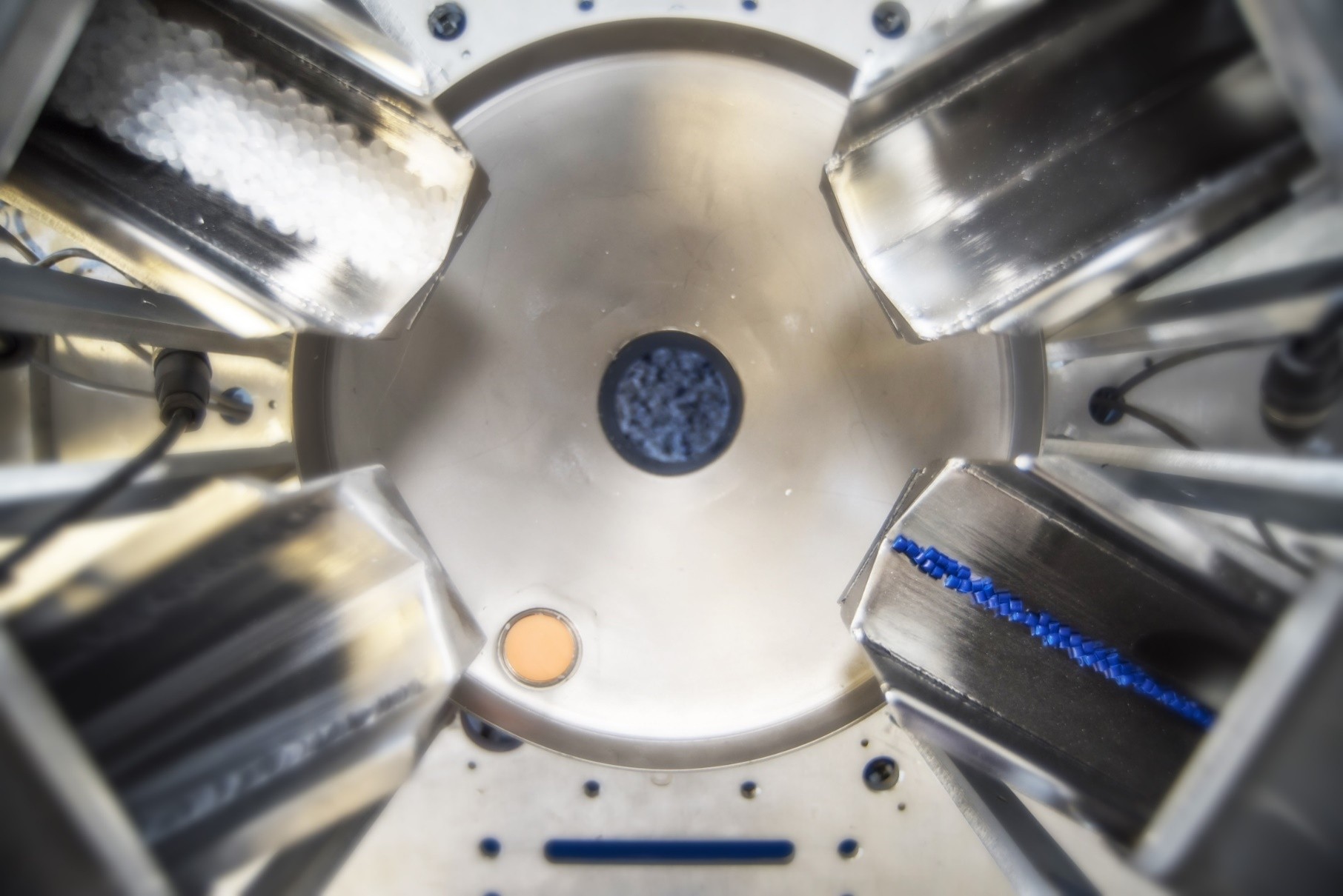
Pipe and profile consistency begins with the intended formulation reaching the extruder at a stable rate. Conveying, blending, drying, powder or regrind feeding, storage and controls should be reviewed as one system—not as isolated machines.
Total throughput alone is not enough. Each ingredient rate, refill behavior, feeder fit and the complete formulation influence the result.
Continuous gravimetric blenders →Measure combined resin consumption and coordinate monitoring, production records or qualified closed-loop extruder-speed control.
Throughput control systems →Size pumps, receivers, filtration, distances, vertical lift, routing and controls around the whole material path and expansion plan.
Central conveying systems →PVC dry blend, heavily filled compounds and unusual powders: do not assume a standard pellet-handling system will behave correctly. Material testing, bulk density, aeration, flooding, dust containment, feeder geometry and the actual formulation require application review.
A melt pump meters molten polymer and builds controlled downstream pressure. A screen changer or filter removes unwanted solids. Many projects involve both, but they solve different problems and should not be selected as one interchangeable “melt system.”
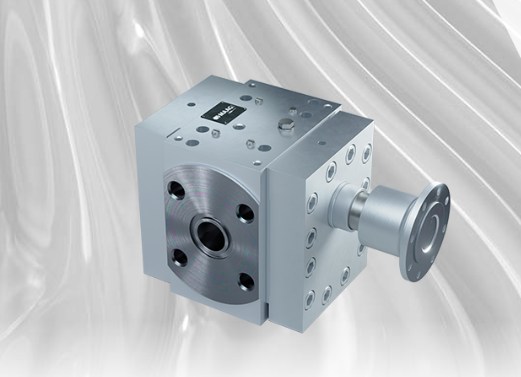
Start here for output pulsation, unstable die pressure, restrictive tooling, extruder pressure relief or controlled flow. GU, EP, SP and MP are different operating envelopes—not a good/better/best ranking.
Open the melt-pumping path ↑
Start here for gels, black specks, rising differential pressure, short screen life, frequent changes, regrind or contamination. Match the technology to the actual stream and intervention tolerance.
Open the filtration path ↑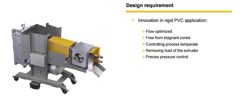
MAAG positions extrex⁶ EC specifically around the flow and temperature-control requirements of rigid PVC. Its flow-optimized execution and shaft cooling are intended to support controlled continuous conveying while limiting stagnation and thermal stress. It is a dedicated application branch—not a universal replacement for thermoplastic pumps or an automatic fit for every PVC formulation.
This is routing guidance, not root-cause proof. Trend several variables together whenever possible before assigning the problem to one supplier or one component.
The solids path must deliver the intended formulation at a stable rate before downstream equipment can be evaluated fairly.
Contamination level, fineness, screen loading, allowed interruption and operator involvement drive the first technology choice.
A gear pump may separate downstream pressure-building and metering from the extruder when that is the actual bottleneck.
Use the appropriate outside-dimension or ultrasonic method to establish what changes, where it changes and whether the adjustment helped.
The forming and downstream equipment may be the dominant variable even when material, melt and gauges are working as intended.
A useful control plan assigns every measurement and actuator to a variable it can influence. More equipment does not fix an undefined process response.
It can move, dry when required, meter, blend, route and record material. It cannot correct a poor die, unstable calibration, cooling imbalance or haul-off behavior.
A filter removes qualified unwanted solids; a pump meters flow and builds pressure. Neither automatically fixes variable feed, incomplete melting, a bad die or downstream limitations.
A gauge shows what the product is doing. Closed-loop control still requires a compatible actuator, proven process response, limits, interlocks and clear command ownership.
Use these tools to quantify line rate, capability and known instability before the equipment review. Results remain planning estimates until the application is confirmed.
Connect cross-sectional area, density, speed and production rate for pipe and profile output planning.
Compare process spread, centering and the tolerance window after a reliable measurement method is established.
Separate feed, melting, filtration, pump, controls and downstream causes using synchronized evidence.
Browse throughput, cooling, resin conveying, pump, filtration, calibration and ultrasonic planning tools.
These answers establish the starting architecture. Final equipment selection still requires the actual formulation, line conditions, size range, tolerances, layout and intended control response.
A finished equipment specification is not required. Gauge Advisor can separate the material-handling, melt-system, forming and measurement questions, then route each part to Advanced Blending Solutions, MAAG or LaserLinc without forcing one manufacturer to own the entire line.