Updated August 21, 2026
Pressure is one of the most useful clues on an extrusion line, but one number on an HMI is not a diagnosis. When someone tells me the pressure is fluctuating, the first questions I ask are: Where is it measured? What shape does the trend make? What else moves at the same time?
A screen pack that is slowly loading, a feeder that pulses during refill, an extruder that surges only at higher screw speed, and an electrically noisy pressure transducer can all be described as “pressure instability.” The corrective action is completely different in each case.
Connected process path: Stable die pressure starts upstream with consistent resin condition and feed, then depends on filtration and controlled melt delivery.
Related next steps: continuous gravimetric blenders, throughput-control weigh hoppers, desiccant resin drying systems, extrusion pressure stability, polymer filtration and melt pumps, and central resin conveying systems.
Do not start by changing temperatures
Pressure at the die often correlates with output, but the relationship is not perfectly one-to-one because polymer viscosity can also change. Dynisco’s treatment of closed-loop extrusion control describes the die as a pressure-flow device and explains why die-entrance pressure is useful for detecting output changes.[1]
Head pressure, filter inlet, filter outlet, pump inlet, pump outlet, and die pressure do not tell you the same thing.
Separate a slow trend from a repeating cycle, random spike, step change, or high-frequency noisy signal.
Compare pressure with feeder events, screw rpm, motor load, melt temperature, pump speed, line speed, and product dimensions.
Give the line time to respond, mark the trend, and document the result before making the next adjustment.
One transducer cannot isolate the entire line
Pressure measurements along the barrel, before and after the screen pack, at the inlet and outlet of a gear pump, and at the die each provide different diagnostic information.[2] Your line may not have all of these points, but the map below shows why sensor location matters.
No melt pressure yet, but interruptions here can create a repeating output and pressure cycle downstream.
Reflects the extruder, downstream resistance, melt viscosity, and the operating point of the screw-and-die system.
Useful for seeing the load the extruder is developing ahead of the screen pack or melt filter.
Compared with P2, this helps separate filter restriction from downstream die or pump demand.
Shows whether the pump is receiving a stable, adequately pressurized melt supply from the extruder and filter.
Best location for evaluating the pressure delivered to the die and whether the finished product sees stable melt flow.
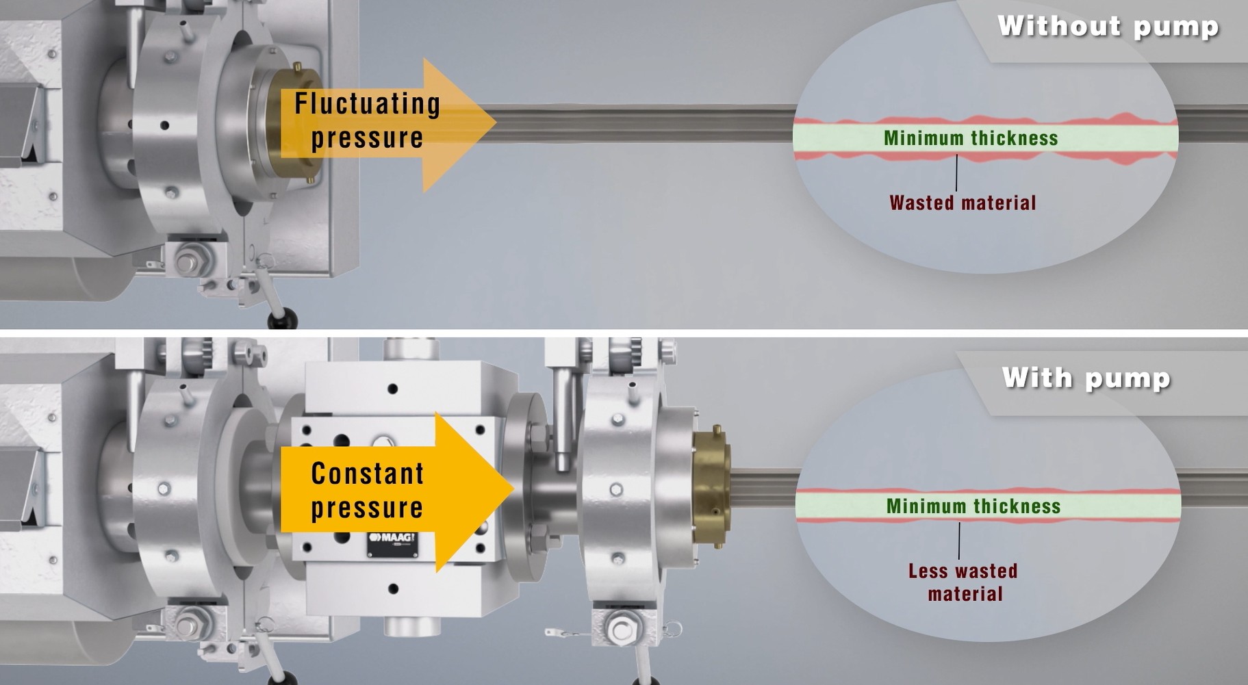
Six pressure patterns that point in different directions
A screenshot of a single pressure number is rarely enough. Save the trend at a useful time scale, then classify what the signal is doing.
Screen loading, increasing die restriction, or a cooler / more viscous melt.
Feeder refill, receiver cycles, solids-conveying instability, or a control loop that is hunting.
Contamination, agglomerates, intermittent feed interruption, or an electrical / sensor issue.
A screen change, setpoint change, material transition, valve movement, or a sudden restriction.
True fast pulsation is possible, but first verify the transducer, wiring, scaling, and sample rate.
Move downstream: cooling, internal air, vacuum sizing, puller, air ring, tension, winding, or measurement.
Why a small pressure change can matter: Dynisco presents a theoretical estimate that a 1% head-pressure variation may correspond to roughly 1–3% output variation depending on polymer rheology.[1] Treat that as an illustration, not a universal conversion factor. The actual relationship on your line depends on the polymer, temperature, die geometry, operating point, and where pressure is measured.
Extrusion pressure-fluctuation troubleshooting matrix
Search a symptom or filter by system. Start with the pressure pattern, then trend the listed variables before replacing equipment or changing several settings.
| Pressure pattern | First suspects | What to trend next | Best next resource |
|---|---|---|---|
| 1Head or die pressure slowly rises during the run FiltrationDie / melt |
Screen-pack loading, contamination buildup, cooler melt, die restriction | Pressure before and after the filter, differential pressure, motor load, actual melt temperature Open the diagnosis ↓ |
Extrusion filtration selection guide |
| 2Pressure differential across the screen changer keeps increasing Filtration |
Filter loading, undersized area, too-fine media, high contaminant loading | Upstream pressure minus downstream pressure, change interval, material / regrind lot Open the diagnosis ↓ |
Filtration & screen changer selector |
| 3Pressure cycles at a repeatable interval FeedingExtruderControl |
Receiver or feeder refill, solids-conveying surge, solid-bed breakup, hunting control loop | Cycle time versus refill events, feeder actual rate, motor load, screw rpm, pump-speed command Open the diagnosis ↓ |
Resin handling equipment selector |
| 4Pressure changes when a feeder or vacuum receiver refills Feeding |
Refill algorithm, pressure pulse, leaking refill valve, scale vibration, changing bulk density | Feeder actual versus target rate, refill output, load-cell signal, receiver valve timing Open the diagnosis ↓ |
Resin conveying & blending systems |
| 5Random sharp spikes or short pressure interruptions MaterialFiltrationInstrument |
Agglomerate, contamination, intermittent feed, degraded material, noisy transducer signal | Pressure at a second location, product defect timing, feeder events, screen differential, sensor raw signal Open the diagnosis ↓ |
Plastics extrusion troubleshooting guide |
| 6A sustained pressure change follows a resin, color, filler, or regrind change PolymerFeedingTemperature |
Viscosity / MFR change, bulk-density change, moisture, additive package, blend ratio, melt-temperature shift | Lot number, blend recipe, dryer data, actual melt temperature, feeder mass rate Open the diagnosis ↓ |
Extrusion throughput & line speed calculator |
| 7Pressure and extruder motor load rise together ExtruderFiltrationDie |
Growing downstream restriction, colder / more viscous melt, excessive output demand, screw / barrel condition | Motor load, pressure by location, heater output, melt temperature, screw speed Open the diagnosis ↓ |
Melt pumps & polymer filtration |
| 8Oscillation appears only at higher screw speed or throughput ExtruderFeedingPump |
Feed limitation, incomplete melting, solids instability, screw-design limit, control tuning, insufficient pump inlet margin | Pressure amplitude versus screw rpm, melt temperature, motor load, feeder capacity, pump inlet pressure Open the diagnosis ↓ |
Melt pump selector |
| 9Pressure drops or spikes during and after a screen change FiltrationControl |
Cavity filling / venting, piston movement, backflush sequence, incorrect change speed, air entrapment | Screen-changer sequence steps, upstream / downstream pressure, product response, recovery time Open the diagnosis ↓ |
Filtration technology guide |
| 10Melt-pump inlet pressure is low or unstable PumpExtruderFiltration |
Upstream starvation, overloaded filter, weak extruder output, inlet-pressure loop tuning, excessive pump demand | Pump inlet / outlet pressure, pump rpm, screw rpm, filter differential, pump torque and temperature Open the diagnosis ↓ |
Pipe, tubing & profile melt-delivery guide |
| 11Pump outlet is stable while pump inlet still oscillates PumpUpstream |
The pump is isolating the die, but upstream instability still exists and may reduce operating margin | Pump inlet minimum, filter differential, screw-speed correction, pump torque, dimensional trend Open the diagnosis ↓ |
How melt pumps improve output stability |
| 12Pump outlet pressure or pump speed hunts around setpoint PumpControlInstrument |
Competing control loops, aggressive PID tuning, bad scaling, delay, sensor noise, changing die demand | Setpoint, process value, controller output, pump rpm, extruder rpm, sensor signal Open the diagnosis ↓ |
Film & sheet melt-delivery guide |
| 13Melt pressure is stable but thickness, OD, wall, or profile still drifts DownstreamMeasurement |
Cooling, vacuum sizing, internal air, puller / haul-off, line speed, air ring, web tension, winding, measurement | Dimension versus line speed, cooling / vacuum / air variables, cross-web profile, puller and tension Open the diagnosis ↓ |
26-problem extrusion troubleshooting guide |
| 14Pressure trace is noisy but the product and other process variables are not Instrument |
Damaged or poorly installed transducer, thermal shift, plugged port, wiring / grounding, scaling, sampling | Second sensor, raw versus filtered signal, zero / calibration history, temperature and electrical events Open the diagnosis ↓ |
Cpk/Ppk & process capability calculator |
Eight places extrusion pressure instability commonly begins
These sections are intentionally ordered from upstream to downstream. Open the section that best matches your trend, but do not ignore the interfaces between systems.
1Inconsistent material feeding, blending, or conveyingFeedingResin handlingRefill cycle
Before blaming the screw or die, verify that the extruder is receiving a consistent mass of material. A hopper can look full while bridging, rat-holing, segregation, poor regrind flow, or an intermittent receiver cycle changes what actually enters the feed throat.
Clues that point upstream
- The pressure cycle repeats at the same interval as a vacuum receiver dump or feeder refill.
- Blend ratio, regrind level, pellet shape, fines, or bulk density recently changed.
- The hopper level, feeder output, or material stream visibly pulses.
- Pressure and motor load fall together, then recover.
- The problem disappears when the line is fed from a stable test lot or at a lower rate.
What I would check first
- Trend feeder target versus actual mass rate and mark every refill event.
- Inspect for bridging, leaking refill valves, blocked vent filters, poor flexible connections, or a feed-throat temperature problem.
- Compare virgin, regrind, color, and additive feed streams separately.
- Check whether a volumetric feeder is being asked to handle large bulk-density variation.
- For loss-in-weight systems, review vibration, load-cell stability, refill control, and pressure pulses.
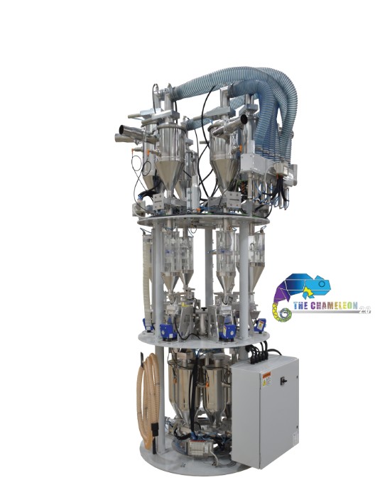
Continuous gravimetric blending depends on measuring and controlling the actual mass flow of each component rather than assuming feeder speed equals material rate. Published control-system work for polymer extrusion treats load-cell feedback and mass-flow estimation as core parts of the blender architecture.[5] The practical lesson is simple: if the pressure oscillation lines up with a receiver dump, feeder refill, or another material-handling event, correct that event before tuning the extruder.
2Screw, barrel, solids-conveying, or melting instabilityExtruderScrew & barrelMelting
A single-screw extruder is not automatically a perfect metering device. Screw geometry, barrel condition, feed-throat behavior, polymer friction, melting pattern, and downstream resistance all influence output. Some instabilities become much more visible as screw speed and output increase.
Likely contributors
- Screw design that is poorly matched to the resin or throughput range
- Worn screw flights or barrel clearance that increases leakage flow
- Unstable solids conveying or intermittent feed-throat slip
- Incomplete melting or solid-bed breakup in the compression / metering region
- Drive-speed instability, venting disturbances, or excessive pressure demand
- Running beyond the stable melting or conveying capacity of the machine
What I would trend
- Screw rpm, motor load, head pressure, and actual melt temperature on the same time base.
- Pressure amplitude at several screw speeds while holding the downstream line as steady as possible.
- Whether the cycle remains after feeding and refill events are eliminated.
- The age, wear history, and resin suitability of the screw and barrel.
- Whether the problem began after a rate increase, screw change, material change, or maintenance event.
Recent experimental work continues to show that solid-bed breakup can occur in the compression and metering zones and that its frequency changes with operating conditions.[6] That does not mean every oscillation is solid-bed breakup, but it is a legitimate mechanism when a repeatable surge remains after feed, temperature, and instrumentation are verified.
3Melt-temperature, viscosity, or material-property changesPolymerTemperatureViscosity
Pressure is a function of both flow and resistance. A more viscous melt generally requires more pressure through the same flow path, while a less viscous melt may show lower pressure. That sounds simple until screw speed, output, die swell, shear heating, moisture, regrind, and material transitions move at the same time.
Common causes
- Failed heater, thermocouple, cooling valve, or poorly tuned temperature zone
- Actual melt temperature changing even though barrel setpoints look stable
- Resin lot, grade, MFR / MFI, additive, filler, or color concentrate change
- Different regrind level, particle size, thermal history, or degradation
- Moisture or hydrolysis in hygroscopic polymers
- Startup before the full adapter, screen changer, pump, and die reach thermal equilibrium
What I would verify
- Measure or trend actual melt temperature rather than relying only on setpoints.
- Check heater output, zone recovery, cooling activity, and thermocouple behavior.
- Mark resin lot, blend recipe, regrind percentage, and dryer data on the pressure trend.
- Compare pressure at the same screw speed and verified output, not merely at the same setpoint.
- Inspect whether lower pressure is accompanied by bubbles, surface defects, or property loss.
Dynisco notes that pressure changes can indicate heater, screw / barrel, feed, screen-pack, die, startup, or shutdown problems.[3] In other words, pressure is a diagnostic signal, but it must be interpreted alongside temperature and material history.
4Screen-pack loading, contamination, or screen-changer disturbanceFiltrationContaminationScreen change
A slowly rising upstream pressure is one of the clearest filtration clues, especially when the pressure difference across the screen pack grows over time. Fine screens remove smaller contamination but can load faster, and the screen pack itself adds resistance to the melt path.[4]
What the trend may mean
- Slow rise: screen loading, contamination, gels, degraded material, or a growing die restriction
- Step down after change: expected reduction from a clean screen, provided the line recovers smoothly
- Spike / dip during change: piston movement, cavity filling, venting, or backflush sequence
- Frequent changes: filter area, media, contamination level, or technology may not fit the application
- Pressure rises with PCR: contaminant loading and material variability may be increasing together
What I would check first
- Trend pressure immediately before and after the filtration device.
- Calculate differential pressure and compare it by time, output, and material lot.
- Record screen mesh / media, active area, screen-change interval, and contamination type.
- Review the exact change, venting, and backflush sequence rather than only the final pressure.
- Inspect for bypass, seal, alignment, or sensor-location problems.
Screen-change disturbances are often tied to piston movement, temporary volume loss, cavity venting, or the way the control system compensates during cleaning and change sequences. MAAG’s maax BF documentation describes pressure-dependent piston positioning and volume compensation designed to limit pressure fluctuations during screen cleaning and venting cycles.[8]

5Melt-pump inlet conditions or control-loop interactionMelt pumpControlsInlet pressure
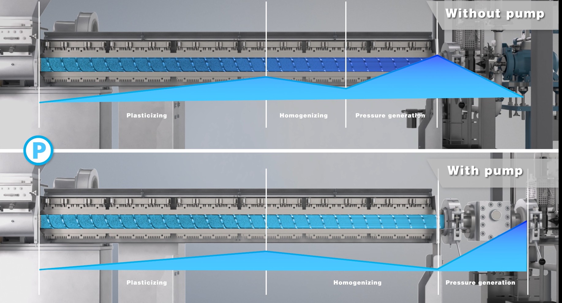
A gear pump is a positive-displacement device that can deliver low-pulsation, repeatable melt flow to the die. MAAG describes high volumetric efficiency and low pulsation as contributors to uniform output.[7] But the pump still depends on a stable, properly controlled inlet supply.
What can go wrong
- The pump is demanding more melt than the extruder and filter can supply.
- Filter loading reduces inlet-pressure margin as the run progresses.
- The extruder-speed loop and pump-speed loop are both chasing the same disturbance.
- PID settings are too aggressive, too slow, or tuned for a different material / output.
- Pressure scaling, sensor delay, deadband, or alarm limits are incorrect.
- Startup transfers from manual to automatic control before the process is thermally stable.
What I would trend
- Pump inlet and outlet pressure, pump rpm, screw rpm, and controller output.
- Filter differential and minimum pump-inlet pressure through the run.
- Pump torque / load and temperature, especially during rate changes.
- The exact control architecture: which drive controls inlet pressure, outlet pressure, or throughput?
- Whether the oscillation begins when a loop is placed in automatic or a setpoint is changed.
MAAG’s pump-control documentation emphasizes precise control of extruder or pump speed, integrated filter monitoring, and quick control of pump inlet pressure.[9] A stable pump outlet with a moving inlet can mean the pump is doing its job, but it does not make the upstream disturbance disappear.
6Die, adapter, tooling, or flow-path restrictionDie / toolingRestrictionThermal balance
The die converts pressure into product flow, so a change in die resistance changes the operating point of the line. Deposits, degraded polymer, a cold zone, a partially blocked channel, valve movement, mandrel position, deckle adjustment, or a coextrusion feedblock issue can all affect pressure.
Clues that point downstream of the filter
- Pressure before and after filtration moves together, but filter differential remains normal.
- A step change follows a die adjustment, valve movement, maintenance, or product-width change.
- One heater zone draws abnormal current or cannot hold temperature.
- Pressure is stable overall, but a persistent cross-web or circumferential thick / thin area remains.
- Purging reveals degraded material, restricted flow, or a dead spot.
What I would check first
- Confirm actual temperatures and heater output through the adapter, pump, feedblock, and die.
- Compare pressure before the die with the product profile, not only the average dimension.
- Review recent die cleaning, assembly, torque, mandrel, lip, deckle, or valve changes.
- For coextrusion, trend each layer’s extruder / pump rather than only total pressure.
- Inspect the flow path under the proper safe maintenance procedure.
7Pressure-transducer, installation, or data problemInstrumentationSignal qualityCalibration
Not every pressure fluctuation is physical. A damaged sensing tip, plugged or poorly located port, thermal zero shift, incorrect scaling, loose connection, electrical noise, or an overly aggressive sample / display setting can create a convincing but misleading trend.
Signs to question the signal
- High-frequency jitter has no matching change in product, motor load, temperature, or another pressure point.
- The reading shifts after heat-up, shutdown, wiring work, or transducer replacement.
- Two nearby sensors disagree substantially under otherwise steady conditions.
- The signal clips at a fixed value, jumps by exact increments, or responds to unrelated electrical events.
- The port contains degraded polymer or the diaphragm may have been damaged during cleaning.
Verification steps
- Compare with another pressure point and independent process variables.
- Check model, pressure range, output type, scaling, wiring, grounding, and display filtering.
- Review zero / calibration history and the manufacturer’s thermal and installation guidance.
- Confirm the sensing tip is correctly installed and not recessed, over-torqued, or coated.
- Evaluate the raw signal before assuming the software trend is a faithful picture of the process.
Pressure-transducer location and condition matter because head-pressure changes are used to diagnose screen packs, heaters, screw / barrel condition, feed problems, and startup / shutdown behavior.[3] A bad signal can therefore send the entire troubleshooting effort in the wrong direction.
8A downstream problem that only looks pressure-relatedCooling & sizingHaul-offMeasurement
If melt pressure is stable while the product continues to drift, move downstream. Pressure can influence dimensions, but it is not the only variable that controls film gauge, tubing OD, pipe wall, profile geometry, bubble stability, or roll quality.
Tubing, pipe & profile
- Cooling-water temperature, flow, tank length, or uneven heat removal
- Vacuum-sizing instability or leaking / changing internal air pressure
- Puller speed, belt pressure, slip, or mechanical distortion
- Tool alignment, sag, drawdown, or unsupported hot product
- Measurement location, axis count, calibration, or response time
Blown film, cast film & sheet
- Air-ring balance, IBC, frost-line movement, ambient air, or bubble rotation
- Chill-roll temperature, nip, draw, neck-in, or web-speed variation
- Cross-direction die profile versus machine-direction mass-flow variation
- Web tension, guiding, winding, or roll-formation problems
- Scanner sampling and whether the trend is MD, CD, random, or edge-related

Pressure behavior must be interpreted by polymer and process
Do not copy a pressure target, melt-temperature correction, screen strategy, or pump recommendation from another polymer and assume it applies. Confirm the grade, rheology, additives, moisture requirement, regrind level, and die geometry.
Thin film can show small mass-flow changes quickly. Check regrind and fines, feed consistency, melt temperature, die pressure, and whether a screen-change event lines up with a gauge disturbance.
High die resistance can make pressure trends especially visible. Separate viscosity or restriction changes from downstream OD, wall, vacuum sizing, cooling, and puller effects.
A resin-grade or melt-temperature change can shift viscosity and pressure. Do not confuse downstream shrinkage or crystallization effects with a true melt-delivery problem.
Dry-blend feeding, shear history, temperature, pressure, and motor load need to be read together. Raising temperature simply to lower pressure can create a different problem in a heat-sensitive material.
Drying matters. Moisture can change viscosity through hydrolysis and may lower pressure while bubbles, surface defects, brittleness, or property loss become worse.
Bulk density, particle geometry, contamination, filler level, and MFR can move at the same time. Trend feed behavior and filter differential instead of blaming every variation on the screw.
A total line-pressure value can hide an unstable individual layer. Monitor each extruder or pump stream and compare the layer-specific trend with the final profile.
When a melt pump helps—and when it does not
A melt pump can be one of the most effective ways to stabilize flow delivered to the die, but it should be applied to a defined process problem rather than used as a substitute for diagnosis.
A melt pump is a strong fit when…
- Die pressure and output show repeatable pulsation after feeding, temperature, and filtration are reasonably controlled.
- Tight film gauge, sheet thickness, OD, wall, profile, or layer tolerances require more consistent metering.
- The extruder is carrying excessive pressure-generation duty and usable throughput is limited.
- Coextrusion or multi-output systems need independently controlled melt streams.
- The process needs better separation between melting / mixing and downstream pressure generation.
A melt pump will not correct…
- An empty hopper, bridging, wrong blend, leaking refill valve, or unstable feed system.
- Wet, degraded, contaminated, or highly variable resin by itself.
- An overloaded filter that is allowed to exceed its operating window.
- A badly balanced, damaged, blocked, or thermally unstable die.
- Cooling, internal air, vacuum sizing, puller, air ring, web tension, winding, or measurement problems.
- A damaged pressure transducer or badly tuned control architecture.
Because gear pumps provide positive-displacement, low-pulsation conveying, they can decouple downstream flow from some screw-output variation.[7] The application still requires correct pump sizing, adequate inlet conditions, suitable filtration, and a control strategy that does not make the extruder and pump fight each other.
Run a controlled pressure-fluctuation test
The goal is not to collect every tag in the PLC. It is to capture enough synchronized information to determine which system moves first.
Allow the extruder, adapter, filtration, pump, feedblock, and die to reach thermal and production stability before judging a trend.
Trend pressure and supporting variables together. A ten-minute pressure chart and a one-hour feeder report are difficult to correlate.
Flag refills, receiver dumps, screen changes, backflushes, recipe changes, setpoint changes, and line stops directly on the trend.
Do not change three temperature zones, screw speed, and puller speed at once. You lose the ability to learn from the response.
Residence time and thermal lag matter. Give the material and equipment enough time to reach the measurement point.
A root cause is much more convincing when the same controlled change produces the same pressure and product response twice.
| Trend | What it helps isolate | Useful comparison |
|---|---|---|
| Pressure by location | Extruder, filtration, pump, and die segments | P2–P3 differential; P4 minimum; P5 product response |
| Screw rpm & motor load | Output demand, restriction, solids conveying, and melting behavior | Pressure amplitude and actual melt temperature |
| Feeder / blender actual rate | Refill pulses, starvation, segregation, and changing mass feed | Receiver events, hopper weight, and pressure cycle period |
| Actual melt temperature | Viscosity and thermal variation | Heater output, resin lot, pressure, and motor load |
| Pump rpm, torque & controller output | Pump demand, control hunting, and inlet limitation | Pump inlet / outlet pressure and extruder rpm |
| Line speed, puller, air, vacuum & tension | Downstream dimensional variation | Pressure and inline OD / wall / gauge profile |
| Finished-product measurement | Whether pressure variation actually reaches the product | Machine-direction timing, cross-direction profile, and scrap events |
How much is pressure instability costing the line?
The cost is usually larger than the scrap bin. Pressure-related instability can create material giveaway, lower usable speed, added screen-change labor, longer startups, more inspection, rework, customer complaints, and conservative process targets.
Average thickness or wall is raised to protect the minimum specification.
Estimate process ROIThe line is held below capacity because higher speed makes pressure or dimensions unstable.
Calculate throughputHigher variation reduces Cpk / Ppk even when the average remains near target.
Model Cpk & PpkOperators compensate, change screens, adjust settings, sort product, and restart the line.
Track the right statisticsExtrusion pressure fluctuation FAQ
What causes extrusion surging?
Extrusion surging can originate in inconsistent feeding, unstable solids conveying or melting, screw / barrel wear, changing melt temperature or viscosity, screen-pack loading, a restrictive die, melt-pump inlet limitation, control-loop hunting, or a bad pressure signal. The trend shape and sensor location are what narrow the list.
Why does extrusion pressure slowly increase during a run?
A gradual rise often points to increasing resistance, especially a loading screen pack or melt filter. It can also result from a cooler or more viscous melt, accumulating die deposits, or a changing material stream. Trend pressure before and after filtration to see whether differential pressure is growing.
What is an acceptable amount of melt-pressure fluctuation?
There is no universal acceptable percentage. The answer depends on the polymer, die, pressure location, product tolerance, measurement response, and whether the variation reaches the finished product. Establish the line’s normal baseline and correlate pressure amplitude with output, gauge, OD, wall, or profile variation.
Can a screen changer cause a pressure spike or drop?
Yes. Piston movement, cavity filling, venting, and backflushing can disturb pressure during a screen change. The important questions are the size and duration of the disturbance, how quickly the line recovers, and whether the finished product is affected.
Will a melt pump eliminate all pressure fluctuations?
No. A correctly applied melt pump can greatly improve the stability of flow delivered to the die, but it does not fix feed starvation, wet or degraded resin, a loading filter outside its design window, a blocked die, downstream cooling / haul-off problems, or faulty instrumentation.
Where should melt-pressure transducers be installed?
Common diagnostic locations include the extruder barrel or head, before and after the screen pack / changer, at the inlet and outlet of a gear pump, and at the die. The correct number and locations depend on the line design, required controls, pressure limits, and safety review.
Why can dimensions change while melt pressure stays stable?
Cooling, vacuum sizing, internal air pressure, puller or haul-off speed, air-ring / IBC conditions, web tension, winding, die distribution, and the measurement system can all move the product without creating a noticeable change in the available pressure signal.
Does lower pressure always mean the process improved?
No. Lower pressure may mean a cleaner filter or lower die resistance, but it may also reflect lower output, feed starvation, higher melt temperature, lower viscosity, moisture-related degradation, a material change, or a bad sensor. Always compare pressure with output, temperature, motor load, and product quality.
References
These sources support the process principles in this guide. Equipment limits, safe procedures, resin conditions, and control settings must still be confirmed for the specific line. Disclosure: Gauge Advisor is an authorized sales and applications support representative for MAAG Group and Advanced Blending Solutions. Their materials are cited where they describe specific equipment functions.
- Dynisco, “Closed Loop Pressure Control for the Extrusion Process.”
- Dynisco, Extrusion Operations, pressure-measurement locations and control.
- Dynisco, “Melt Pressure Measurement: Environmental Effects.”
- Dynisco, The Extrusion Processors Handbook, screen packs and screen changers.
- Previdi et al., “Control System Design for a Continuous Gravimetric Blender,” 18th IFAC World Congress, 2011.
- Knaup et al., “Improvement in an Analytical Approach for Modeling the Solid Conveying and Melting Behavior in Single-Screw Extrusion,” 2024.
- MAAG, “Gear Pumps,” polymer-processing performance and low-pulsation conveying.
- MAAG, maax BF Automation Solution for Backflush Screen Changers.
- MAAG, maax PC Pump Control System for Extrusion Line Integration.
Need help evaluating the equipment side of the pressure problem?
Gauge Advisor is an authorized sales and applications support representative for MAAG Group and Advanced Blending Solutions. I support MAAG melt pumps, screen changers, filtration systems, and controls, along with Advanced Blending Solutions resin conveying, blending, feeding, and drying equipment. Gauge Advisor supports equipment selection and integration for the manufacturers represented here; independent process consulting is not offered.
Send the pressure trend and a short description of the line. Gauge Advisor will respond within one business day, often within a few hours, and let you know what additional information is needed to evaluate the application.
- Product and polymer grade
- Extruder size and screw speed
- Current throughput
- Pressure location, average, and fluctuation range
- Screen / filter type and change interval
- Motor load and actual melt temperature
- Any melt-pump inlet / outlet data
- How the finished product changes