Updated August 21, 2026
Measuring tubing diameter and wall thickness sounds straightforward until the product is soft, oval, eccentric, multilayer, moving at production speed, or still changing dimension as it cools. The first question is not which gauge to buy. It is which geometric feature the specification actually controls, and whether that feature must be measured inline, offline, or both.
This guide compares contact tools, laser micrometers, ultrasonic wall systems, automated sample inspection, and full-surface measurement for medical tubing, catheters, guidewire coatings, wire and cable, hose, pipe, and other precision extrusions. It also includes an interactive measurement-path selector, tube-geometry calculator, searchable application matrix, process map, and direct links to the most relevant Gauge Advisor and LaserLinc resources.
Separate OD, ID, wall, ovality, concentricity, full-length profile, and localized surface defects.
Record whether the product is hot, soft, wet, moving, cooled, cut, reinforced, coated, or assembled.
Decide what must be measured inline for process feedback and what must be verified offline for release.
Control guiding, tension, coupling, alignment, sample conditioning, formulas, and correlation to the accepted method.
Connected process path: Route OD and ovality questions to laser micrometers, wall and concentricity questions to ultrasonics, and finished-part defects to the matching inspection path.
Related next steps: laser micrometers, medical-tubing measurement selector, medical-tubing wall-thickness measurement, wire and cable measurement selector, and medical-tubing surface-defect detection.

Five tubing dimensions that are often confused
A drawing may list OD, ID, wall, ovality, and concentricity as if they are interchangeable. They are not. Each describes a different part of the tube geometry and may require a different measurement method.
The external size of the tube. Laser micrometers are well suited to continuous, non-contact OD measurement. Contact tools may be appropriate for rigid parts and lower-volume checks.
The lumen size. ID may be measured directly on a cut sample, calculated from OD and a resolved wall profile, or evaluated with an application-specific bench method.
The material between the inner and outer surfaces. One wall reading does not describe the complete circumference when the tube is eccentric.
The difference between maximum and minimum diameter using the formula required by the specification. Fixed-axis systems estimate ovality from the views they capture.
How centered the inner geometry is relative to the outside. Definitions vary, so report the formula, minimum wall, maximum wall, and wall range.
What the geometry tells you
A laser micrometer sees the outside silhouette. It can measure OD and, with multiple axes, provide a stronger estimate of ovality. It does not see through the tube wall.
An ultrasonic system measures acoustic interfaces through the wall. It provides wall-thickness and concentricity information when the material and geometry produce usable echoes. For a complete cross-section with OD and calculated ID, pair ultrasonics with a laser diameter measurement.[3]
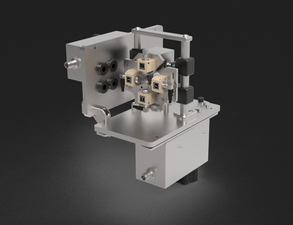
For a cut polymer sample, a controlled mandrel and automated rotation can provide OD, ID, wall, and ovality without depending on manual caliper force. For rigid or metallic tubing, ultrasonic bench inspection may be a better fit.
Choose a preliminary tubing measurement path
Select the primary feature being measured, workflow, product behavior, and geometry. The result identifies a sensible LaserLinc starting architecture and the questions that still need application review.
Select your requirements above
The result will explain the recommended measurement stack and important limitations.
How the main tubing measurement methods differ
Use the four paths below to narrow the method without reading eight dense cards at once. The visible summary identifies the best fit; open a comparison only when you need the method-level limitations.
 Manual contact example
Contact and prepared-sample methods
Best for rigid parts, quick checks, cut sections, and features that can be presented to a controlled contact or optical method.
Compare the contact and optical methods
Fast and portable for rough OD, ID, or length checks on rigid parts.
- Low cost and familiar
- Operator force and jaw placement matter
- Soft tubing can compress
- Not continuous or inline
Better resolution and controlled spindle force than basic calipers when the contact geometry is suitable.
- Useful for rigid OD or wall checks
- Anvils must match the feature
- Still sensitive to deformation and alignment
- Slow for full-length coverage
Useful for cut sections, profiles, lumen geometry, and features visible in a prepared view.
- High magnification
- Requires lighting, focus, edge definition, and positioning
- Usually sample-based
- Sectioning can alter soft geometry
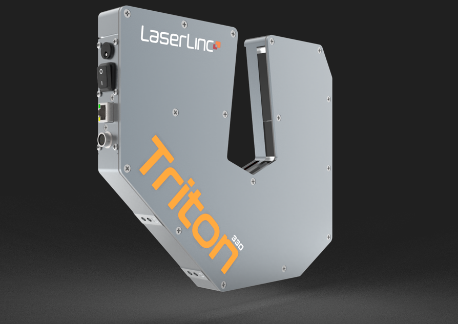 Triton shown
Laser micrometers
The strongest starting point for non-contact OD, width, height, and estimated ovality when contact would deform the product or continuous data is required.
What laser micrometry measures and misses
Outside diameter, width, height, flat-to-flat dimensions, and axis-based outside geometry without touching the product.
One, two, or three synchronized axes can be selected around the product shape, orientation risk, range, and installation.
Wall thickness, inside diameter, concentricity, or a complete orientation-independent surface contour.
 UltraGauge shown
Ultrasonic wall measurement
Use pulse-echo ultrasonics when wall thickness and concentricity must be measured without cutting the tube.
What an ultrasonic application must prove
Individual wall values and circumferential wall distribution can support minimum wall and concentricity calculations.
Add synchronized laser OD when the workflow also needs outside geometry, ovality, and calculated ID.
Material velocity, frequency, alignment, water path, temperature, layers, lumens, braid, and attenuation affect feasibility.
 Metron shown
Automated sample, profile, and surface inspection
Use a controlled bench or scanning platform when spot checks cannot describe the part or the inspection must be repeatable across operators and lots.
Compare bench, full-length, and surface workflows
Fixtures, automatic rotation, controlled contact force, laser, or ultrasound improve repeatability for first article, incoming, and release inspection.
A controlled platform measures tapers, bumps, transitions, and dimensional trends along a catheter, guidewire, shaft, or tube.
Dedicated surface mapping finds scratches, pits, gels, bumps, cracks, and other localized raised or recessed flaws that average diameter may miss.
Measuring OD and ovality with laser micrometers
Laser micrometers project one or more measurement beams across the product and calculate dimensions from the resulting shadow. Because the system does not contact the tube, it avoids the compression error that can occur with calipers and mechanical micrometers.
Measures one orientation. It can be a strong fit for known non-round geometry, width, height, flat-to-flat dimensions, constrained installations, or larger ranges.
Measures two fixed orientations at the same time. It provides better coverage than one axis, but a rotated oval or lobed shape may still be underrepresented.
Provides three synchronized views for stronger average-diameter and estimated-ovality confidence on round and elliptical products.[2]
If true orientation-independent contour, circularity, or localized surface shape is required, a full-surface technology may be more appropriate than fixed shadow axes.
Axis count is only one selection factor. The measuring range, smallest feature, required accuracy, line speed, product vibration, guide arrangement, wet or dry environment, communications, and physical access can be equally important. Review the complete single-, dual-, and triple-axis laser micrometer guide before assuming more axes are automatically better.
Measuring wall thickness, concentricity, and ID with ultrasonics
Ultrasonic pulse-echo measurement sends a sound pulse through the tube wall and measures the time between reflected interfaces. Thickness depends on the measured transit time and the acoustic velocity used for the material. ASTM E797/E797M describes the core pulse-echo thickness principle and the need to understand application-specific capabilities and limitations.[10]
LaserLinc UltraGauge systems provide live wall-thickness and concentricity data during extrusion. When a Triton laser micrometer is added, the system can combine outside geometry with the ultrasonic wall profile to present OD, ovality, wall thickness, concentricity, and calculated ID.[3]
Use the Ultrasonic Transducer Selector for a preliminary compatibility check, then review the actual material and geometry. The ultrasonic alignment guide explains why product centering and transducer position are critical to stable wall data.
Calculate derived ID, ovality, and wall uniformity
Use this calculator for a quick engineering check. It does not replace the drawing definition or a validated measurement routine. Derived ID assumes the entered OD and wall represent the same cross-section and that the wall value is appropriate for the calculation.
Where should tubing be measured?
The same tube can have different dimensions while hot, wet, tensioned, unsupported, cooled, relaxed, or cut. Select each stage to see what it is best suited to measure and what can mislead the result.
1. Die exit and early cooling: understand the moving target
Immediately after the die, the tube may still be soft, swelling, drawing down, responding to internal air pressure, and changing dimension as it enters cooling. A measurement here can be valuable for fast process feedback, but it may not equal the final released dimension.
- Document the measurement distance from the die.
- Record melt, water, and ambient temperatures when correlation matters.
- Avoid contact that can deform the hot tube.

Match the tubing application to a starting measurement approach
Search by product, feature being measured, material, or workflow. Use the process filters to narrow the matrix.
| Application | Critical measurements | Common starting approach | Main limitation or check | Related resource |
|---|---|---|---|---|
| Soft medical tubing extrusionMedicalInline | OD, ovality, wall, ID, concentricity | Triton laser micrometer plus UltraGauge ultrasonic wall system; Total Vu for visualization and control. | Support the soft tube without deformation; correlate hot inline dimensions with cooled samples. | Medical selector |
| Catheter shaft or microtubeMedicalSmall OD | OD, ovality, wall, concentricity, short defects | Small-range multi-axis laser; ultrasonic feasibility review; optional FlawSense for localized defects. | Very small walls and geometry require appropriate range, signal separation, alignment, and product handling. | Medical extrusion guide |
| Multilayer medical tubingMedicalLayered | Overall OD, total wall, selected interfaces, concentricity | Laser OD plus ultrasonic sample evaluation for the interfaces that must be resolved. | Not every acoustic interface is distinct. Adhesion layers, braid, fillers, and similar velocities can complicate interpretation. | Transducer selector |
| Multi-lumen catheter tubingMedicalComplex | OD, lumen dimensions, web thickness, wall distribution | Laser OD plus application-specific sample inspection or validated optical method; test ultrasonics before specifying. | Complex internal geometry may not be fully represented by standard single-lumen ultrasonic calculations. | Medical solutions |
| Balloon tubing or controlled bump/taperMedicalProfile | OD by length position, transitions, taper, ovality | Laser micrometer with encoder and bump/taper or virtual ring-gauge software. | Measurement rate, encoder resolution, product acceleration, and control delay must match the feature length. | Setup guide |
| Guidewire or coated mandrelMedicalCoating | OD, coating build, taper, localized defects | Laser OD for continuous geometry; Metron for full-length profile; FlawSense when surface integrity is critical. | OD change does not identify which side or layer changed. Coating eccentricity may require additional methods. | Metron guide |
| Cut rigid polymer tubingOfflinePolymer | OD, ID, wall, ovality, wall distribution | BenchLinc OD/ID with controlled mandrel support, automatic rotation, and load-based contact control. | Mandrel selection, sample straightness, cut quality, and handling can influence repeatability. | BenchLinc guide |
| Nitinol, hypotube, or cannulaMedicalMetal | OD, ID, wall, concentricity, full-length variation | BenchLinc UT with ultrasonics and optional Triton laser measurement; Metron for long-part profiles. | Surface condition, curvature, wall range, acoustic response, and part holding require review. | Nitinol guide |
| Full-length catheter or delivery shaftMedicalFull length | OD profile, ovality, taper, transitions, local defects, length position | Metron with the LaserLinc measurement technology that matches the feature. | Part straightness, rotation, support, scan speed, and profile recipe must be controlled. | Full-length inspection |
| Industrial hose or flexible tubingIndustrialFlexible | OD, ovality, wall, reinforcement position, surface defects | Laser OD; ultrasonic wall if acoustically compatible; FlawSense for critical surface or braid defects. | Product sag, vibration, braid, rubber attenuation, and wet environments may drive the design. | Surface defect guide |
| Plastic pipe extrusionIndustrialPipe | Average OD, out-of-roundness, wall, minimum wall, length | Large-range laser or multi-axis measurement plus ultrasonic wall, depending on size and process. | The applicable product standard may define average OD and out-of-roundness differently from a tubing drawing.[9] | Extrusion guide |
| Wire insulation or cable jacketWire & cableInline | OD, ovality, insulation or jacket wall, concentricity | Laser OD plus UltraGauge wall measurement when the conductor and insulation construction are compatible. | Conductor geometry, metallic interfaces, foamed insulation, and multiple layers affect ultrasonic interpretation. | Wire & cable solutions |
| Twisted pair or multi-conductor cableWire & cableComplex | Peak and valley, maximum envelope, lay-related variation | Application-specific multi-axis or profile measurement with max/min algorithms. | A simple average OD can hide geometry variation created by twisting and conductor orientation. | Wire selector |
| Multiple parallel strands or filamentsWire & cableMulti-strand | Individual strand diameters and position | LaserLinc multi-strand measurement using an application-specific Axion configuration. | Spacing, crossing, vibration, and the number of simultaneous products determine feasibility. | Wire measurement guide |
| Critical surface-defect inspectionAll marketsDefects | Raised and recessed flaws, defect length, height, depth, and location | FlawSense 3D surface mapping, inline or on a controlled inspection platform. | Define the smallest defect of concern using known good and known bad samples, not only a generic defect name. | Surface inspection page |
| Incoming, first-article, or release inspectionOfflineQA | Dimensions required by the drawing and validation plan | BenchLinc, Metron, or a documented manual method selected around the part and risk. | Define sample conditioning, fixture, method, calibration, uncertainty, decision rule, and correlation to production data. | Rigid tubing guide |
The same gauge does not behave identically on every tube
Material affects deformation, acoustic velocity, echo strength, thermal contraction, surface appearance, and handling. Construction adds another layer of complexity.
Contact force can compress the part. Stabilize the product without flattening it, and correlate hot inline values with cooled dimensions.
Grade, moisture, temperature, and multilayer construction can change acoustic behavior. Confirm ultrasonic settings using representative production material.
Flexible thin-wall products may sag or vibrate. Density and temperature influence acoustic calculations, while cooling history affects final size.
Measurement location and thermal stabilization become especially important. Protect sensors and guides from the process environment.
High compliance and acoustic attenuation can challenge contact and ultrasonic methods. Application testing is important.
Each interface may produce an echo, but not every layer is resolvable. Braid and reinforcement can create complex signals and local geometry.
Outside geometry can be measured normally, but internal webs and lumens may require specialized optical, destructive, or validated sample methods.
Ultrasonic bench methods can measure wall and concentricity when curvature, surface condition, and wall range support a reliable pulse-echo result.
Conductor shape, insulation foaming, multiple layers, shields, braids, and jackets change what can be measured ultrasonically and how diameter should be defined.
Calibration, traceability, uncertainty, and method correlation
A measurement system is not validated simply because it displays more decimal places. The complete method includes the sensor, fixture, software, calibration standards, environment, operator workflow, part condition, and acceptance rule.
Compare the system against traceable standards or suitable reference artifacts across the working range, not only at one convenient point.
Evaluate repeated measurements, part repositioning, multiple operators, fixtures, shifts, and product lots where those variables matter.
The uncertainty and decision rule should be appropriate relative to the tolerance and risk. NPL identifies traceability, uncertainty, environment, alignment, and thermal effects as core dimensional-metrology considerations.[8]
Inline, offline, contact, optical, and ultrasonic methods may measure under different conditions. Correlate them intentionally instead of assuming numerical identity.
NIST defines metrological traceability as an unbroken chain of calibrations to specified reference standards, with each link contributing to measurement uncertainty.[7] For laser micrometers, clean, certified diameter pins are a practical way to verify scale and linearity. Use the Calibration Pin Selector to bracket the actual product range.
For a deeper treatment of the distinction between the two, see gauge repeatability versus accuracy. Use the Cpk/Ppk calculator only after the measurement method and process data are shown to be stable and meaningful.
Common tubing measurement mistakes
Open each item for the practical check I would make before blaming the sensor or changing the process.
1. Calculating ID from OD and one wall reading
The formula ID = OD – 2 × wall assumes the wall value represents both sides of the same section. An eccentric tube can have one acceptable wall and one thin wall. Measure the wall distribution or use a method that resolves the complete profile.
2. Compressing soft tubing with a caliper or micrometer
Excessive jaw force, a small contact area, or angled placement can change the dimension being measured. Compare operators and force levels, then use non-contact measurement or a controlled fixture when the method is not repeatable.
3. Treating one diameter as proof of roundness
One axis can report a stable value while the tube is oval in another orientation. Two axes improve coverage, but fixed views still do not equal a complete contour. Match the axis count and method to the allowable shape error.
4. Ignoring product presentation
Vibration, sag, twist, water droplets, unsupported length, guide wear, and inconsistent tension can add noise or bias. Stabilize the product at the measurement point without changing its shape.
5. Assuming ultrasonics will resolve every layer or lumen
Ultrasonic measurement depends on usable acoustic interfaces. Similar material velocities, thin layers, braid, fillers, attenuation, and complex geometry can merge or weaken echoes. Test representative samples before committing to the architecture.
6. Poor ultrasonic alignment or signal acceptance
A numeric output is not proof of a strong echo. Review signal quality, alignment, centering, gain, gates, and dropout behavior. Automatic positioning can reduce operator variability during startup.
7. Comparing methods without matching conditions
A hot, tensioned inline tube and a cooled, relaxed cut sample are different measurement states. Define correlation conditions and expected offsets before declaring one method wrong.
8. Sampling too little of the product
A few spot checks can miss machine-direction drift, a localized neckdown, taper transition, or short surface defect. Increase temporal, circumferential, or full-length coverage based on the failure mode.
9. Using diameter data to make a surface-quality claim
Average OD may remain in tolerance while a scratch, pit, blister, gel, or crack passes through the process. Use dedicated surface inspection when localized defects are critical.
Inline control, offline validation, and the closed measurement loop
The strongest quality strategy often uses inline measurement for immediate process visibility and offline inspection to verify the cooled product and finished workflow.
Use laser OD, ultrasonic wall, surface mapping, or a combined system based on the actual process variable and specification.
Use timestamps, encoders, and line-speed information so a dimensional event can be traced to the correct location and operating condition.
Diameter control may adjust puller speed, extruder output, or internal air. Wall and concentricity control require different actuators and an understanding of loop interactions.
BenchLinc or Metron can compare the finished sample with dynamic inline data and support documented QA workflows.
LaserLinc Total Vu brings laser, ultrasonic, and FlawSense data into a common visualization, analysis, reporting, and control environment.[6] Control still requires a capable actuator, a known transport delay, appropriate filtering, alarm logic, recipe control, permissions, and validation.
Information needed to select a tubing measurement system
The more specific the inputs, the faster the system can be narrowed to a realistic configuration.
- Product and marketMedical tube, catheter, guidewire, hose, pipe, wire, cable, or another extrusion.
- Material and constructionPolymer grade, metal alloy, layers, braid, filler, lumen count, color, transparency, and surface finish.
- Size rangeMinimum and maximum OD, ID, wall, width, height, and expected variation.
- Specification and formulasNominal values, tolerances, ovality definition, concentricity definition, and minimum wall requirement.
- WorkflowInline, at-line, laboratory, incoming inspection, full-length scanning, or final release.
- Process conditionsLine speed, product temperature, water, vibration, tension, internal air, and available installation space.
- Measurement objectiveMonitoring, alarms, SPC, closed-loop control, validation, traceability, or automated accept/reject.
- Known failure modesOvality, thin wall, eccentricity, drift, taper error, gels, scratches, pits, bumps, or other defects.
- Samples and current methodKnown good and bad parts, existing gauge data, correlation results, and current inspection procedure.
- Integration needsPLC protocol, OPC-UA, analog outputs, encoder, recipes, user permissions, reports, and data retention.
Related Gauge Advisor resources
Use the guide that matches the next decision in your process.
Tubing diameter and wall-thickness measurement FAQs
What is the best way to measure soft tubing OD?
A non-contact laser micrometer is usually the strongest starting point because it does not compress the product. The installation must still support the tube without flattening it and control vibration, twist, and water at the measurement point.
Can a laser micrometer measure wall thickness or ID?
Not by itself. A laser micrometer measures the outside silhouette. Wall thickness and concentricity require ultrasonic or another suitable internal-geometry method. ID can then be calculated from a resolved OD and wall profile or measured on an appropriate cut-sample system.
Can ultrasonics measure OD?
Ultrasonics primarily measures wall interfaces. Some systems may estimate geometry from acoustic paths, but for a complete outside profile LaserLinc pairs UltraGauge with a laser micrometer. This produces OD, ovality, wall, concentricity, and calculated ID in one visualization.
How do you measure tubing ovality?
Measure maximum and minimum diameter around the circumference using the method and formula required by the specification. A single axis is insufficient when orientation is unknown. Two or three axes improve coverage, while full-contour technology is appropriate when true orientation-independent shape is required.
What is the difference between concentricity and eccentricity?
Both describe the relationship between inner and outer geometry, but formulas vary. Some specifications use center offset, others use minimum-to-maximum wall ratios or wall variation. State the formula explicitly and retain the underlying minimum and maximum wall values.
How do you measure wall thickness without cutting the tube?
Inline or bench pulse-echo ultrasonics can measure wall thickness non-destructively when the material, wall range, geometry, coupling, and acoustic interfaces are suitable. Representative samples should be evaluated before final system selection.
Why does inline OD differ from the lab result?
The inline tube may be hot, wet, moving, tensioned, internally pressurized, or not fully relaxed. The lab sample may be cold, dry, cut, and conditioned. Define a correlation procedure that controls time, temperature, position, and sample condition.
How many laser axes are needed for tubing?
It depends on shape, orientation, range, and risk. Single axis can be appropriate for a controlled dimension or non-round shape. Dual axis adds a second view. Triple axis generally provides stronger average-diameter and estimated-ovality confidence for round or elliptical tubing. Review the complete axis guide for application-specific tradeoffs.
Can the same system measure medical tubing and wire insulation?
The same technology families may be used, but the exact range, product support, acoustic interfaces, measurement algorithms, line speed, environment, and validation workflow can differ. Review each application separately.
What information should I send for a LaserLinc application review?
Send product drawings or dimensions, material and construction, tolerance, line speed, measurement workflow, known defects, current method, installation space, environment, samples, data needs, and whether the goal is monitoring, control, or final inspection.
References and source notes
The references are collapsible to keep the article readable. They open automatically when printing.
Open technical references and source notes12 sources
Gauge Advisor is an authorized LaserLinc sales and applications support partner. LaserLinc sources are used for current product capability and architecture. Independent standards and metrology sources are included for measurement principles, traceability, uncertainty, pipe dimensions, ultrasonic thickness, and medical quality-system context. No competitive equipment suppliers are cited.
- LaserLinc, Laser Micrometers. Current Axion and Triton measurement capabilities, materials, multi-strand applications, and integration.
- LaserLinc, Triton Three-Axis Laser Micrometers. Three-axis average-diameter and estimated-ovality positioning.
- LaserLinc, Ultrasonic Wall Thickness Measurement. UltraGauge wall, concentricity, alignment, and combined laser-ultrasonic profile architecture.
- LaserLinc, Sample Inspection. Metron and BenchLinc workflows for automated profile, OD/ID, wall, and ultrasonic inspection.
- LaserLinc, Surface Flaw Detection. FlawSense full-surface mapping, defect detection, and contour measurement.
- LaserLinc, Process Visualization. Total Vu integration, visualization, analytics, documentation, communications, and control tools.
- NIST, Metrological Traceability: Frequently Asked Questions. Traceability as an unbroken calibration chain with stated uncertainty.
- National Physical Laboratory, Fundamental Good Practice in Dimensional Metrology. Measurement uncertainty, traceability, environment, alignment, thermal effects, and specification decisions.
- ASTM D2122-22. Standard test method for diameter, wall thickness, out-of-roundness, length, and straightness of thermoplastic pipe and fittings.
- ASTM E797/E797M-21. Pulse-echo ultrasonic thickness measurement principles and application limitations.
- U.S. FDA, Quality Management System Regulation. QMSR implementation effective February 2, 2026 and alignment with ISO 13485:2016.
- ISO 10555-1:2023. General requirements for sterile, single-use intravascular catheters. Use the product-specific standard and drawing for actual dimensional acceptance requirements.
Need a LaserLinc tubing measurement recommendation, quote, or application review?
Gauge Advisor is the authorized LaserLinc sales and applications support partner. I help manufacturers select, quote, integrate, and support LaserLinc systems for tubing, catheter, guidewire, pipe, hose, wire, cable, and precision-part measurement.
Gauge Advisor supports equipment selection and integration for the manufacturers represented here; independent process consulting is not offered. Send the details below and I will respond within one business day, often within a few hours.
- Product, material, and construction
- OD, ID, wall, and tolerance range
- Ovality or concentricity definition
- Inline, offline, or full-length workflow
- Line speed and measurement environment
- Known defects or current measurement problem
- PLC, reporting, and control needs
- Drawings, photos, or representative samples