Updated August 21, 2026
A laser micrometer does not measure a catheter, cannula, or guidewire in the abstract. It measures the silhouette that the part presents inside the measurement field. If the part sags, wanders, twists, tilts, or is squeezed by the fixture, a capable sensor can report a repeatable number that does not represent the intended dimension. The best setup therefore combines the right LaserLinc micrometer with the right support, motion, inspection sequence, software, and validation method.
Connected process path: Start with the required feature and part presentation, then combine the sensor, fixture, motion, and software needed for repeatable catheter, cannula, or guidewire inspection.
Related next steps: medical-device measurement and inspection, medical-tubing measurement selector, laser micrometers, medical-tubing wall-thickness measurement, and medical-tubing surface-defect detection.

Reliable catheter measurement has five connected parts
Teams often begin by asking whether they need one, two, or three laser axes. That matters, but it is not the first decision. Start by defining the feature being measured and the part state, then build the complete measurement chain around it.
LaserLinc describes its laser micrometers as adaptable components within integrated measurement solutions, and its sample-inspection platforms add part holding, motion, automated recipes, and Total Vu reporting rather than leaving the user to assemble a loose collection of instruments.[1][4] That distinction is important in medical manufacturing, where the fixture and inspection sequence can contribute as much variation as the sensor itself.
How should the part be presented to the measurement system?
Select the product that most closely matches the application. The result identifies the likely support method, measurement architecture, and the first condition I would verify with representative samples.
Soft catheter or microtube: stabilize without reshaping it
A small flexible tube may sag below the measurement centerline, wander laterally, or flatten when it contacts a fixture. A feed-through guide, carefully positioned rollers, or a purpose-built through-hole support can improve repeatability, but the guide clearance and contact condition must be proven on the actual material.
- Start with the lowest-contact support that keeps the measurement location stable.
- Check whether friction, tack, curve memory, temperature, or guide contact changes the displayed diameter.
- Use a short sample study with the fixture installed, not only a free-air gauge repeatability test.
Five ways part presentation can create measurement error
NIST dimensional-metrology guidance identifies alignment, artifact geometry, elastic deformation, support geometry, temperature, and motion as recurring contributors to measurement uncertainty.[11][12] On a catheter or guidewire, those effects often appear as the following practical problems.
The measurement location drops below the intended centerline. A long unsupported span can also bend differently from sample to sample.
The part moves through different regions of the field or contacts guides unpredictably, producing a noisy or biased trend.
The part axis is not normal to the measurement plane. The projected silhouette can become larger than the true cross section.
A soft tube can flatten under a clamp, guide, roller, chuck, drive band, or hand pressure. Repeatable force is not the same as negligible force.
An oval or asymmetric part can produce a different result when placed in a different rotational orientation. The fixture may lock in that bias.
A simple free-span test is useful before ordering a fixture: place the part at the intended measurement height, vary the unsupported length, and observe whether the reading changes as the part is released, rotated, or lightly moved. That test can reveal whether support is needed, but it does not establish the final fixture, uncertainty, or measurement capability.
Choose the support architecture from part behavior and inspection motion
LaserLinc publishes a broad range of V-block, feed-through, roller, chuck, encoder, Metron, and application-specific holding options. The important choice is not which accessory looks most familiar. It is which support creates the most repeatable part state for the required inspection.
V-block fixture
A V-shaped groove self-centers many round, reasonably stiff parts and gives the operator a repeatable placement surface. LaserLinc offers standard and long V-block arrangements for cut parts.[5]
- Strong fit for rigid or semi-rigid round samples
- Simple loading and visual access
- Can support repeatable point measurements
Feed-through guide
LaserLinc feed-through guides mount to a V-block and use replaceable guide sizes to center and support small flexible tubing through the measurement field.[5]
- Reduces sag and lateral movement
- Supports manual feed-through inspection
- Useful where an open V-block does not hold position
Roller or throat guide
Throat-mount, body-mount, plate-mount, rail-mount, and adjustable roller guides support tubing or wire while allowing movement through the micrometer.[5]
- Good for translation through the field
- Adjustable alignment for size changes
- Can be paired with encoders and automation
Spring-loaded chuck or part rotation
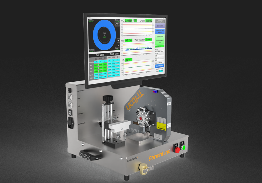
BenchLinc OD uses a spring-loaded chuck and automatic rotation for repeatable outside-geometry profiles. Metron can add motorized part rotation for circumferential inspection.[4][6]
- Reduces manual orientation differences
- Supports multiple angular measurements
- Useful for ovality and asymmetric features
Metron part holders
Metron options include centering cones, magnet V-blocks, centering cups, toggle-clamp V-blocks, cone holders, zero-chucks, throat guides, and motorized part holders.[6]
- Supports vertical or horizontal full-length scanning
- Accommodates hubs, mandrels, varying ends, and long parts
- Can combine translation and rotation
Mandrel and ultrasonic fixtures
When ID, wall, or concentricity controls the requirement, the support method may be part of a BenchLinc OD/ID or BenchLinc UT measurement architecture rather than a simple laser fixture.[4]
- BenchLinc OD/ID for short polymer samples
- BenchLinc UT for rigid and metallic tubing profiles
- Inline UltraGauge for continuous extrusion
Build a preliminary LaserLinc measurement and fixturing path
This selector identifies a practical starting architecture from the part behavior, inspection length, feature being measured, and desired automation. Final selection still requires dimensions, tolerances, photographs or drawings, representative samples, and a review of the actual workflow.
LaserLinc can build the complete inspection architecture
A common purchasing mistake is to compare only micrometer resolution, rate, and range. Those specifications matter, but they do not determine whether a medical-device team receives a reliable workflow. LaserLinc positions its systems as adaptable, integrated measurement, automation, and process solutions rather than isolated sensors.[7][8]
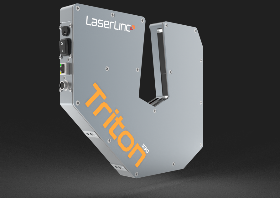
Axion for one- or two-axis applications, Triton for three-axis round and elliptical measurement, UltraGauge for wall, and FlawSense for surface topography.
V-blocks, feed-through guides, rollers, chucks, mandrels, cones, centering cups, throat guides, and custom holders selected from part behavior.
Manual feed, encoder feedback, automatic rotation, full-length Metron scanning, inline motion, markers, cutters, and application-specific automation.
Recipes, displays, calculated values, profile zones, SPC, pass or fail decisions, reports, data export, communications, and control tools.
Virtual demonstrations with customer parts, application engineering, correlation planning, calibration support, and configuration review before release.
LaserLinc publishes a typical four-year warranty for laser micrometers and accessories, no-charge phone and email support for the original purchaser, remote Quick Support, and long-term software support under the stated terms.[9]
Match the part and feature being measured to the LaserLinc system
Fixturing cannot make the wrong measurement technology appropriate. Use this table to separate simple OD checks from full-length profiling, wall measurement, and surface inspection.
| Starting architecture | Best-fit part and workflow | Typical support or holding | What it measures and important boundary |
|---|---|---|---|
| Point or moving OD | Catheter shafts, tubing, guidewires, cannulas, mandrels, and other parts needing outside dimensions at one or several positions. | V-block, feed-through guide, throat or roller guide, adjustable stand, or application-specific holder. | Direct outside silhouette dimensions and ovality estimates according to axis coverage. Does not directly measure wall, ID, concentricity, or hidden defects. |
| Repeatable bench OD | Recurring QA checks on short or manageable samples where a standardized recipe and automated rotation improve consistency. | V-block or through-hole guide for BenchLinc V; spring-loaded chuck and automatic rotation for BenchLinc OD. | OD, ovality, angular profile, statistics, tolerances, and reports. Internal geometry requires another architecture. |
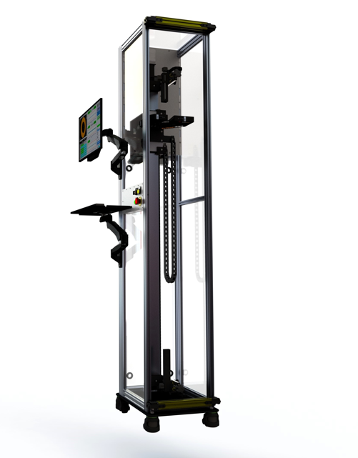
| Full-length profile | Long catheters, guidewires, tapers, proximal and distal zones, transition locations, and complex finished-part profiles. | Vertical or horizontal configuration with cones, V-blocks, cups, chucks, throat guides, motorized part holder, and optional rotation. | Length-positioned outside geometry and configured features; can integrate other LaserLinc technologies. Part holding and profile definitions must match the drawing. |
| Short polymer samples | Short cut polymer tubing samples with an accessible lumen and a suitable mandrel. | Special mandrel, controlled rotation, motor bands, and integrated load measurement. | Laser OD and ovality, wall relative to the mandrel datum, and calculated ID. Soft-part deformation and mandrel fit require validation. |
| Rigid wall profile | Cannulas, hypotubes, NiTi, stainless steel, and compatible rigid tubing needing wall and concentricity along length. | Purpose-built ultrasonic fixture and part guides; optional Triton for OD and ovality. | Direct ultrasonic wall and concentricity, with optional outside geometry and calculated ID. Acoustic feasibility and sample handling must be confirmed. |
| Surface topography | Catheters, guidewires, coated shafts, tubing, and components where pits, scratches, cracks, bumps, or other raised and recessed features control acceptance. | Inline or offline guiding selected to maintain centering without masking the defect surface. | Three-dimensional visible surface geometry and outside dimensions. Appearance-only, internal, coating-chemistry, or functional defects may need another method. |
The Medical Tubing Measurement Selector provides a broader starting path when the project includes several features being measured or both inline and offline inspection.
Gauge Advisor helps teams choose the approach, not just the gauge
A useful application review should reduce risk before a quotation is issued. That means understanding the product drawing, how the part behaves, which values are direct or calculated, where the inspection belongs, how operators will load the part, and what evidence the quality team needs to retain.
Matthew’s role in the project
- Translate the product and drawing into a defined feature being measured and inspection sequence.
- Compare V-block, feed-through, roller, BenchLinc, Metron, ultrasonic, and defect-inspection paths.
- Identify where sample testing or custom holding is needed.
- Coordinate LaserLinc application engineering, demonstrations, and feasibility work.
- Develop the quotation and review integration, training, and support expectations.
- Remain involved after the sale for applications questions and local coordination.
What I need from the customer
The fastest route to a good recommendation is a small, complete application package rather than a request for a generic micrometer quote.
- Part drawings or dimensioned sketches with measurement locations
- Minimum, nominal, and maximum OD, wall, ID, and tolerances
- Part length, stiffness, durometer, curvature, coating, braid, and end features
- Current inspection method, fixture, measurement problems, and MSA data
- Desired cycle time, operators, recipes, reporting, and integration
- Representative good, borderline, and known-difficult samples
Practical outcome: the recommendation may be a simple fixture and micrometer, an automated BenchLinc or Metron system, a combined ultrasonic and laser system, or a decision to test the part before specifying anything.
Fixture repeatability belongs in the measurement-system study
Calibration of the laser scale does not validate how the customer part is supported, loaded, translated, rotated, or interpreted. The complete method should include the actual fixture, part family, recipe, operators, environment, and acceptance decision.
State the exact location, orientation, section, profile zone, formula, and whether the reported value is direct, derived, averaged, or inferred.
Document temperature, conditioning, cleaning, support span, curve memory, guide clearance, clamp force, tension, rotation, and loading method.
Use suitable reference standards for the micrometer and representative parts spanning size, stiffness, color, surface, tolerance, and difficult conditions.
Evaluate repeatability, reproducibility, bias, stability, fixture changes, recipe selection, handling, reporting, and borderline decisions.
NIST defines metrological traceability as a property of a measurement result established through a documented unbroken chain of calibrations, each contributing to measurement uncertainty.[13] It is not an automatic label attached to a micrometer. For medical-device manufacturers, FDA’s Quality Management System Regulation became effective February 2, 2026 and incorporates ISO 13485:2016 by reference.[14] LaserLinc equipment can support a controlled quality process, but the manufacturer remains responsible for validating the intended use, procedures, records, maintenance, software configuration, and changes.
Common catheter and guidewire measurement setup mistakes
Buying the micrometer before defining the support method
The part can fit inside the measurement range and still be impossible to present repeatably. Review stiffness, length, curve memory, contact sensitivity, access, and motion before finalizing the gauge and stand.
Using a V-block for every round product
A V-block is simple and effective for many rigid or semi-rigid parts. A very soft tube may conform to the groove, while an oval part may settle in a preferred orientation and hide rotational variation.
Assuming a feed-through guide is noncontact
The laser measurement is noncontact, but the guide is not. Guide diameter, length, material, friction, cleanliness, curve memory, coating, and manual feed force can influence the part.
Calling three-axis diameter a full surface scan
Triton provides three outside-diameter views and improved angular coverage for round and elliptical products. It does not create a complete three-dimensional surface map. Use FlawSense when the defect can occupy a small local region.
Using OD as proof of wall, ID, or concentricity
A tube can maintain outside diameter while its lumen moves or its wall changes. Use the appropriate mandrel-based or ultrasonic system when internal geometry controls acceptance.
Applying too much tension to straighten a guidewire
Tension can improve presentation while also stretching, aligning, or reshaping the part. Define and control the applied condition, and verify that it does not change the dimension or profile being released.
Clamping on a hub, taper, coating, or functional region
A convenient holding point can damage the product, change its shape, or move the measurement datum. The fixture should protect critical surfaces and preserve access to every required zone.
Validating the sensor but not the fixture recipe
Calibration confirms the measurement scale under defined conditions. It does not prove operator loading, guide setup, chuck force, scan speed, profile-zone definitions, or report logic.
Expecting a standard accessory to fit every future part
A fixture should cover the intended product family without becoming so adjustable that setup is ambiguous. Define change parts, recipes, verification checks, and when a new holder or sample study is required.
Catheter, cannula, and guidewire measurement checklist
- Product type and constructionCatheter, tubing, cannula, hypotube, guidewire, mandrel, shaft, braid, layers, coating, and material.
- Complete dimensional rangeMinimum, nominal, and maximum OD, width, height, wall, ID, and feature dimensions.
- Tolerances and formulasUpper and lower limits, ovality definition, taper or transition rules, profile zones, and minimum-wall criteria.
- Length and part behaviorTotal length, supported and unsupported span, stiffness, durometer, sag, curvature, memory, and straightness.
- Surface and contact sensitivityTack, lubricity, coatings, markers, hydrophilic surfaces, braid texture, scratches, and areas that cannot be touched.
- Current methodExisting gauge, fixture, operator steps, reference standard, sample preparation, cycle time, and known disagreement.
- Inspection workflowPoint check, feed-through, rotation, full-length scan, inline measurement, batch size, operators, and desired automation.
- Data requirementsPass or fail, statistics, profiles, reports, CSV, OPC UA, PLC, MES, audit trail, permissions, and record retention.
- Representative samplesGood, borderline, reject, softest, longest, smallest, largest, most curved, and most difficult end condition.
- Commercial and support scopeTiming, quotation needs, virtual demo, sample testing, installation, training, validation support, and service expectations.
Related Gauge Advisor medical measurement resources
Catheter, cannula, and guidewire fixturing FAQs
Do I always need a fixture with a laser micrometer?
No. A short, straight, sufficiently rigid part may be positioned repeatably without a dedicated fixture. Add support when sag, wander, tilt, rotation, vibration, operator handling, or cycle time prevents a capable measurement method. Prove the need with the actual part rather than assuming either free-air or heavy restraint is always better.
When is a V-block the best choice?
A V-block is a strong starting point for round, cut-to-length parts that are stiff enough to rest in the groove without changing shape. It provides simple self-centering and repeatable placement. Validate orientation effects for oval parts and deformation for soft tubing.
When should I use a feed-through guide?
Evaluate a feed-through guide when small flexible tubing cannot remain centered or steady during manual translation. The guide should provide enough clearance for smooth movement while controlling position. Its contact, friction, cleanliness, and effect on the part must be included in the method study.
Are roller guides only for inline extrusion?
No. Roller and throat guides can support inline product, manual feed-through inspection, encoded translation, and automated sample systems. Guide type, spacing, adjustment, runout, product tension, and contact condition determine whether the arrangement is suitable.
Should I choose a dual- or triple-axis laser micrometer?
Choose axis count from shape, angular coverage, size range, installation space, rate, and the consequence of missing orientation-dependent variation. Triton three-axis systems are well suited to round and elliptical products, while Axion one- and two-axis systems can be better for non-round, constrained, hot, multi-strand, or value-focused applications.
How do I inspect a long catheter or guidewire?
Use Metron when the requirement is a length-positioned profile across proximal, body, taper, transition, distal, or other defined zones. Vertical or horizontal configuration, part holders, optional rotation, scan length, profile definitions, and reporting are selected from the actual product.
Can a laser micrometer measure cannula wall thickness?
Not directly. A laser micrometer measures outside geometry. BenchLinc UT is the stronger starting path for compatible rigid cannulas and hypotubes when direct ultrasonic wall and concentricity are required, with an optional Triton for OD, ovality, and calculated ID.
Can LaserLinc build a custom fixture?
LaserLinc offers a broad set of standard accessories and integrated part-holding options, and it supports adaptable, application-specific systems. The right approach may use standard components, configured combinations, or custom-engineered elements under the final project scope.
What is Gauge Advisor’s role?
Gauge Advisor is the authorized LaserLinc sales and applications support partner. Matthew helps define the measurement problem, compare systems and fixtures, coordinate sample testing and LaserLinc engineering, prepare quotations, review integration, and support the application after purchase.
What samples should I send?
Send representative good parts plus the smallest, largest, softest, longest, most curved, most reflective or transparent, tightest-tolerance, borderline, and known-difficult samples. Include drawings, locations, current measurements, and any fixture-related disagreement.
References and source notes
The references remain collapsible so this focused commercial article is easy to scan. They open automatically when printing.
Open technical references and source notes16 sources
Gauge Advisor is the authorized LaserLinc sales and applications support partner. LaserLinc sources are used for current micrometer, fixture, sample-inspection, software, warranty, and integrated-solution information. NIST, FDA, and ISO sources provide noncompetitive metrology, quality-system, catheter, guidewire, and cannula context. No competitive measurement-equipment manufacturer is cited.
- LaserLinc, Laser Micrometers. Current description of outside-dimension measurement, Axion and Triton categories, noncontact operation, and integrated measurement solutions.
- LaserLinc, Triton Three-Axis Laser Micrometers. Current application positioning, three-axis round and elliptical measurement, accessory guides, integration, and Total Vu context.
- LaserLinc, Axion One- and Two-Axis Laser Micrometers. Current fit for one- and two-axis, non-round, hot, constrained, and multi-strand applications.
- LaserLinc, Sample Inspection. Current Metron and BenchLinc architectures, part-holding options, rotation, full-length inspection, wall measurement, and Total Vu workflows.
- LaserLinc, Laser Micrometer Datasheet. V-block, long V-block, feed-through guide, throat-mount, body-mount, plate-mount, rail-mount, adjustable roller, encoder, stand, and accessory information.
- LaserLinc, Metron Product Sheet. Published centering cone, magnet V-block, motorized rotation, centering cup, toggle-clamp V-block, cone holder, zero-chuck, throat guide, and motorized part-holder options.
- LaserLinc, More Than Measurement. Integrated inline and sample-inspection strategy, automation, Total Vu, adaptable solutions, U.S. manufacturing, and support information.
- LaserLinc, Total Vu Process Visualization. Integration of laser, ultrasonic, and FlawSense devices with visualization, analytics, documentation, communication, and control tools.
- LaserLinc, Warranty and Service. Typical four-year laser-micrometer and accessory warranty, support terms, software support, and remote Quick Support information.
- LaserLinc, About. U.S. ownership, design and manufacturing in Fairborn, Ohio, application engineering, adaptable integrated solutions, and service approach.
- NIST, Uncertainty and Dimensional Calibrations. Dimensional uncertainty sources including alignment, Abbe and cosine errors, artifact geometry, support, motion, and thermal effects.
- NIST, Dimensional Metrology. Practical fixturing, elastic deformation, temperature, alignment, artifact geometry, and comparator measurement-error context.
- NIST, Metrological Traceability. Definition and practical elements of a documented calibration chain in which each calibration contributes to measurement uncertainty.
- U.S. FDA, Quality Management System Regulation. QMSR effective February 2, 2026 and incorporation of ISO 13485:2016 by reference.
- ISO 10555-1:2023. General requirements for sterile, single-use intravascular catheters. The applicable drawing and product-specific standard govern the dimensional acceptance method.
- ISO 11070:2014 and ISO 9626:2016. Guidewire, introducer, dilator, and rigid stainless-steel needle-tubing context for the relevant product families.
Review the part, fixture, and measurement method together
Gauge Advisor is the authorized LaserLinc sales and applications support partner. I help catheter, cannula, guidewire, hypotube, medical tubing, and precision-component teams evaluate, select, quote, integrate, and support LaserLinc micrometers, fixtures, BenchLinc, Metron, UltraGauge, FlawSense, and Total Vu systems.
Gauge Advisor supports equipment selection and integration for the manufacturers represented here; independent process consulting is not offered. Send the part drawing, measurement locations, dimensional range, tolerances, material, length, current setup, photos, data requirements, and representative samples when available. I will respond within one business day, often within a few hours.
- Micrometer and axis selection
- V-block, feed-through, roller, and custom fixturing review
- BenchLinc and Metron architecture comparison
- Ultrasonic and FlawSense complementary inspection
- Sample testing and LaserLinc engineering coordination
- Quotations, integration, training, and ongoing support