Wire & cable measurement, inspection and tension control

Wire & Cable Measurement and Tension Control Systems

Compare systems for two jobs: checking the product itself—outside diameter (OD), ovality, wall thickness, conductor centering, and surface defects—and measuring the tension acting on the wire. Start with where the problem occurs: drawing, extrusion, spooling, stranding, taping, cabling, or final quality assurance (QA).

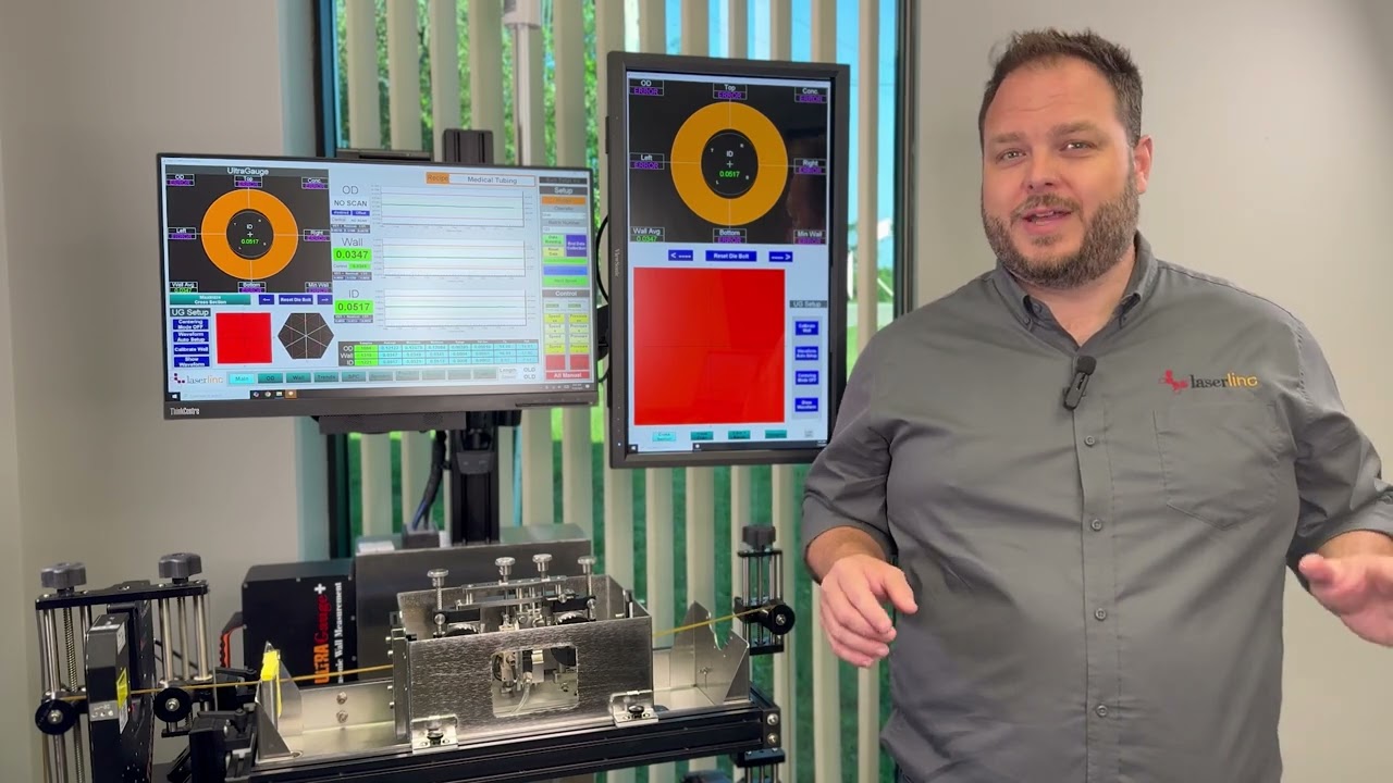
LaserLinc Authorized LaserLinc sales & support partner. Diameter, wall, surface inspection, sample verification, software, and control.
FMS Force Measuring Systems Authorized FMS sales & support partner. Force sensors, wireless data from rotating machines, reporting, brake control, and machine monitoring.
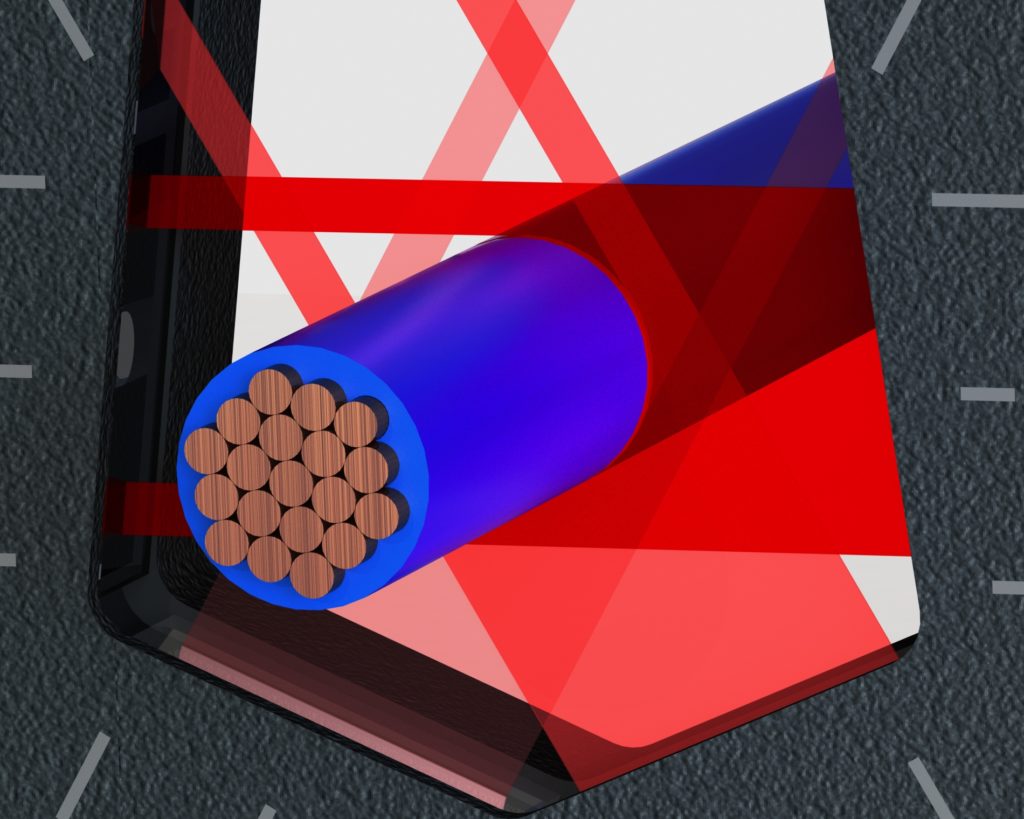
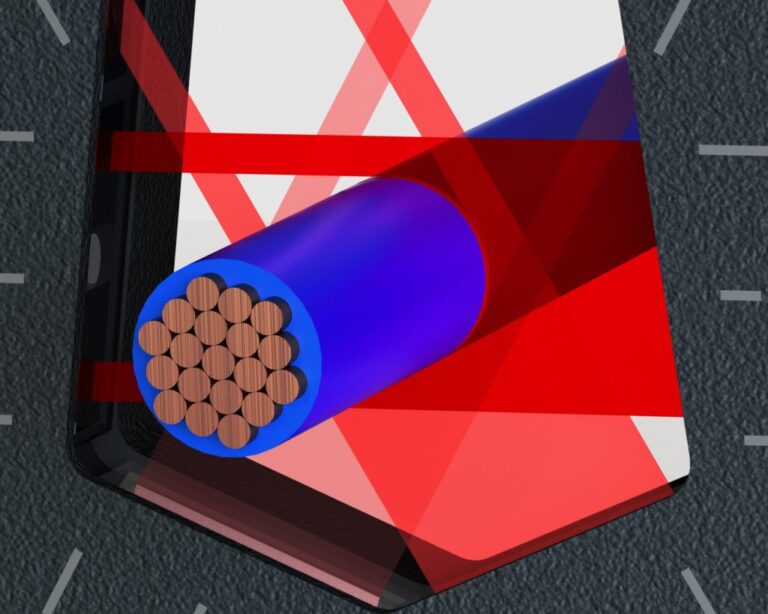
Triple-axis laser micrometer measuring the outside diameter of insulated stranded cable
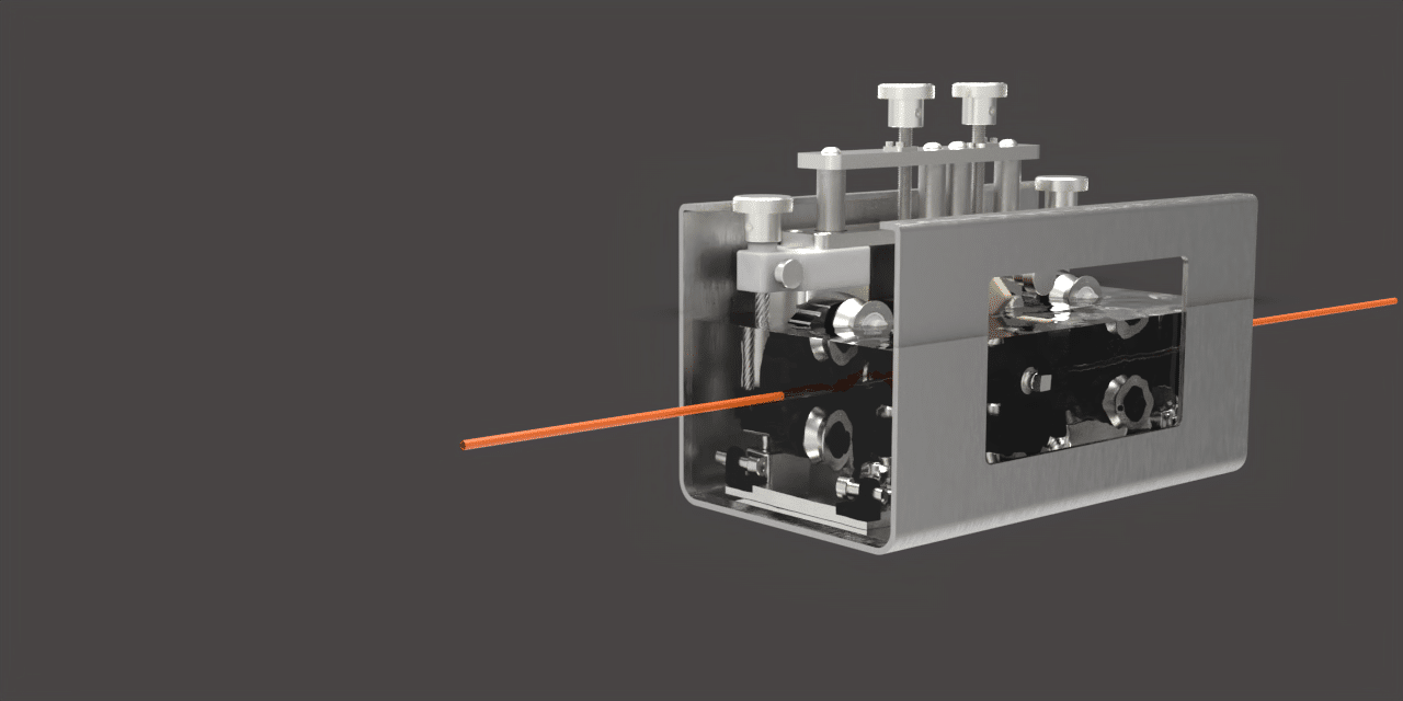
Wire routed over an FMS tension-measuring pulley on production equipment
Measure the product. Monitor the force acting on it. Laser and ultrasonic systems check dimensions and surface defects. Force sensors check tension. Many lines need both.
Diameter, wall & centering
Surface defects & patterns
Tension & control
Authorized partnersLaserLinc and FMS sales, application review, and technical support
MeasurementInline, bench, dimensional, wall, surface, and software options
TensionFixed sensors, wireless data from rotating machines, reporting, safety, and control
LifecycleIntegration planning, training, troubleshooting, and ongoing support
Start with the production step

Where does the problem occur?

First choose the production step where the issue appears. Then decide whether you need to measure the product, monitor tension, or do both.

Product geometry + line tension

Control insulation or jacket geometry during extrusion

First identify the dimensions or defects that matter. Then decide whether tension, alarms, reporting, or automatic control also need attention.

  • MeasureUse a laser micrometer for OD and ovality. Add ultrasonic measurement for insulation or jacket wall and concentricity, or FlawSense for raised and lowered surface defects.
  • Monitor tensionMonitor tension before or after the extruder when conductor movement, stretch, or winding quality affects the process.
  • Use dataShow live readings, trigger alarms, save production records, or send measurements to the line controls.

Fit note: to choose the system, we need the cable construction, conductor shape, line speed, materials, installation space, and control goal. Ultrasonic systems also require a suitable water path between the sensors and product.

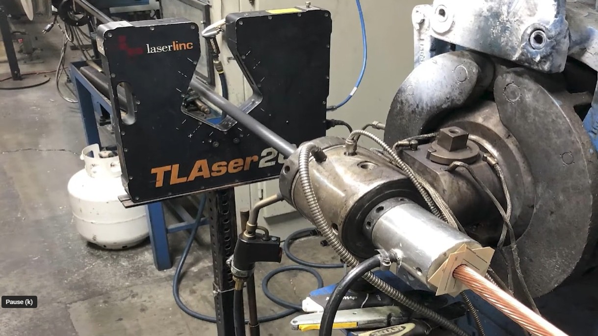
Inline laser micrometer measuring wire beside an extrusion crosshead
An inline laser micrometer checks product diameter next to the extrusion process. Ultrasonic sensors can be added when the line also needs direct wall and concentricity measurement.
Conductor diameter + line tension

Measure conductor diameter and tension during drawing and spooling

These are separate measurements. A laser micrometer checks conductor diameter without touching the wire. A force sensor checks tension where the wire passes over a measuring pulley.

  • MeasureUse a laser micrometer for continuous OD and dimensional drift before coating, insulation, or downstream processing.
  • Monitor tensionUse a stationary force sensor and amplifier when the material passes over a fixed measuring pulley.
  • Diagnose patternsWhen the gauge is linked to an encoder, length-based profiles and fast Fourier transform (FFT) analysis can reveal repeating diameter changes caused by a die or rotating components such as capstans, pullers, and rolls.

Fit note: sensor size is based on the force at the pulley—not material tension alone. That force also depends on wrap angle, pulley weight, speed, and mounting geometry.

Copper wire wound on multiple production spools
Drawing and spooling applications may need both non-contact diameter measurement and a separate force sensor at a suitable measuring pulley.
Finishing geometry + tape application

Track diameter through a tandem taping process

Taping is a finishing or shielding operation commonly applied to an already twisted pair or assembled cable. On a two-head line, diameter stations can establish the incoming geometry, isolate the buildup from the first head, and verify the product after the second head.

  • Before head 1Measure the incoming twisted pair or cable OD and ovality to establish the baseline before tape is applied.
  • Between headsAn optional second gauge isolates the dimensional buildup from the first tape layer and can flag a tape or process problem when it creates a measurable OD or ovality change.
  • After head 2Verify final OD and ovality after the second layer. Comparing stations estimates diametrical buildup; it does not directly measure one-sided tape thickness, overlap, or adhesion.

Fit note: provide the expected OD before and after each head, tape material and nominal thickness, tape width, overlap or lay, line speed, product rotation, available straight sections, guiding, and the dimensional change that should trigger an alarm.

A three-station arrangement separates incoming geometry, first-layer buildup, and final two-layer geometry. A simpler before-and-after layout may be used when there is not enough accessible space between the taping heads.
Each strand + rotating machinery

Measure each strand—not just total line tension

A normal total-tension reading can hide one strand that is too tight and another that is too loose. On rotating stranders and cablers, the measurements must also travel from the rotating section to the stationary controls.

  • MeasureFMS RMGZ200 and RMGZ300 sensors measure tension on individual strands in compatible rotating machines.
  • TransmitRTM X42 wirelessly carries many strand-tension channels. RTM MP Plus carries a smaller mix of encoder, on/off, analog, and limited force-sensor signals.
  • ActAdd on-screen trends and reports, automatic brake adjustment, or cradleGUARD fault monitoring as needed.

Fit note: to configure the system, provide the machine type, number of payoff spools and strands, tension range, rotating power, brake design, programmable logic controller (PLC) connection, and reporting goals.

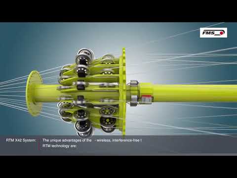
FMS RTM X42 wireless tension monitoring and brake control architecture on a cage strander
RTM X42 can connect rotating strand-tension measurements with visualization, stationary machine controls, documentation, and optional automatic brake adjustment.
Controlled offline inspection

Verify samples and cut components away from the production line

Offline systems support incoming inspection, first articles, research and development (R&D), final inspection, and products that must be rotated or scanned through a controlled fixture.

  • Bench checksBenchLinc OD rotates the sample automatically to measure diameter and ovality from several angles. With the correct setup, it can also support total indicated runout (TIR) checks.
  • Lengthwise profilesMetron feeds and rotates suitable cut products to build a diameter and ovality profile along their full length.
  • DocumentationSaved setups, tolerance checks, statistics, and reports help different operators follow the same inspection method.

Fit note: sample length, flexibility, straightness, fixturing, rotation, expected variation, and inspection time should be reviewed before selecting the bench workflow.

BenchLinc OD system automatically rotating a wire or cable sample for bench inspection
Controlled part holding and automated rotation reduce operator variation during offline OD, ovality, and TIR inspection.
Separate the decisions

Geometry and tension need different measurement paths

A laser gauge cannot measure wire tension, and a force sensor cannot tell you whether insulation is concentric. Many production lines use both, but each system should solve a clearly defined problem.

External geometry

Laser micrometers measure outside diameter (OD) without touching the product. Dual- and triple-axis gauges view it from more than one direction, making ovality and other shape variation easier to see.

Wall & concentricity

Ultrasonic sensors measure insulation or jacket wall thickness. When paired with a laser micrometer, the system can calculate inside diameter (ID) and show how well the conductor or core is centered.

Surface defects & repeating patterns

FlawSense creates a 3D map of raised and lowered surface defects. Total Vu software can also identify repeating diameter patterns or analyze complex cable shapes using FFT, Max/Min, and Multi-Strand tools.

Tension & control

A force sensor calculates wire tension from the force applied to a measuring pulley. Wireless telemetry sends readings off rotating machinery, while software can display, record, or use those readings for automatic brake control.

Interactive selection tools

Choose the problem you are trying to solve

Use the measurement selector for product geometry and inspection. Use the tension selector for force sensing, wireless transmission from rotating machines, brake control, and cradle monitoring.

Measurement & inspection

Which measurement path fits this product?

Answer a few questions about what must be measured, where the measurement happens, the product construction, line speed, software needs, and whether the inspection is inline or offline.

Loading the measurement selector…

If it does not load, open the measurement selector on its own page.

Tension, telemetry & control

Which tension system fits this machine?

Start with the machine and goal. The selector will narrow the likely path for a fixed force sensor, rotating strand measurement, wireless signal transmission, reporting, brake control, or cradle fault monitoring.

Loading the tension selector…

If it does not load, open the tension selector on its own page.

LaserLinc solution families

Measurement, inspection & analysis

Start with the product feature you need to measure. Then decide whether the readings need software, alarms, reports, sample handling, or automatic line control.

01

Inline measurement and inspection

Triple-axis laser micrometer measuring the outside diameter of an insulated stranded cable
InlineOfflineODOvality

Laser micrometers

Non-contact single-, dual-, and triple-axis measurement for wire drawing, insulation, jacketing, taping, cabling, and controlled bench checks.

Best for
Continuous external-dimension measurement and process feedback
Measures
Outside diameter, ovality with multiple axes, dimensional variation, and separated parallel strands with a compatible fixture and software
Limit
Does not directly measure insulation wall, concentricity, or surface topography
Explore laser micrometers Compare single-, dual-, and triple-axis configurations
Ultrasonic sensors measuring insulation wall thickness around a wire or cable during extrusion
InlineWallConcentricity

UltraGauge + AutoPilot

Ultrasonic sensors directly measure insulation or jacket wall thickness during extrusion. When paired with laser OD measurement, they can also calculate ID and concentricity for compatible product constructions.

Best for
Insulation and jacketing lines that need wall and concentricity visibility
Measures
Wall directly; ID and concentricity when combined with OD data
Limit
Material, construction, wall range, water coupling, and sensor access must be reviewed
Check the measurement path View LaserLinc ultrasonic technology
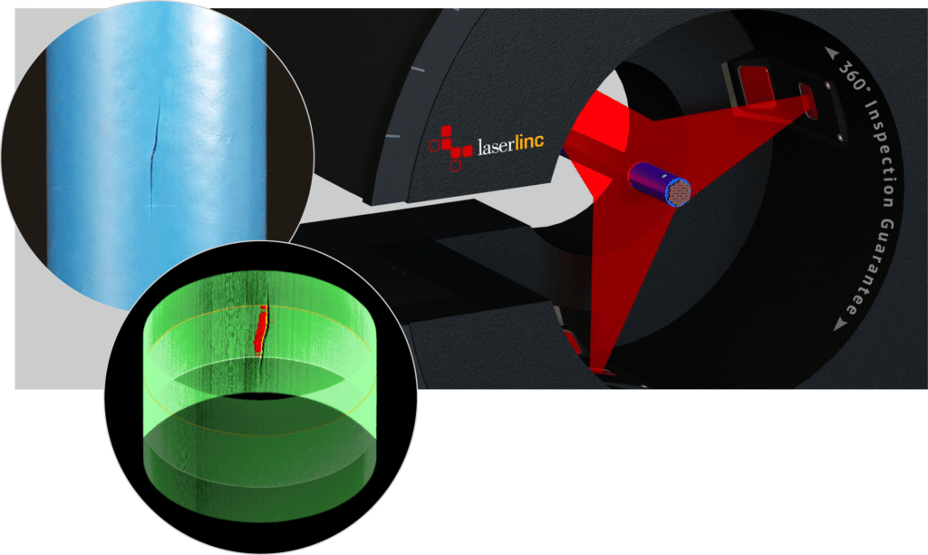
Three-dimensional surface map identifying raised and lowered defects on wire or cable insulation
InlineOfflineOD3D surface

FlawSense

FlawSense combines OD and ovality measurement with a 3D map of raised and lowered surface defects around the product.

Best for
Continuous surface coverage where standard diameter gauging leaves blind spots
Detects
Lumps, pits, slits, scratches, gels, and other flaws that change surface height
Limit
Material appearance, motion, defect geometry, and detection threshold require sample review
Review wire and cable inspection
02

Application software & offline QA

FFT spectrum used to identify repeating diameter variation in wire and cable production
SoftwareFFTMax / MinMulti-strand

Total Vu application software

Total Vu turns data from connected gauges into live displays, alarms, trends, reports, and application-specific analysis for repeating diameter patterns and complex cable shapes.

Best for
Twisted pair, multi-conductor, fiber, and repeating process variation
Analyzes
FFT spectra, peak and valley geometry, strand-by-strand measurements, trends, and alarms
Limit
FFT can reveal periodic geometry related to SRL risk; it does not replace electrical certification
See FFT, Max/Min & Multi-Strand analysis
LaserLinc BenchLinc OD system for automated bench measurement of wire and cable samples
OfflineODOvalityTIR

BenchLinc OD

Controlled bench inspection with automatic sample rotation for repeatable diameter, ovality, and total indicated runout checks.

Best for
Incoming material, first articles, R&D, and finished-sample verification
Measures
OD and ovality from multiple angles; TIR with the appropriate setup
Limit
Offline sample workflow rather than continuous production monitoring
Use the measurement selector View LaserLinc sample inspection
Horizontal Metron system for automated lengthwise inspection of cut wire and cable components
OfflineFull lengthAutomated

Metron

Automated feed-and-rotate inspection for cut-to-length products that need a complete external diameter and ovality profile.

Best for
Wire, cable, fiber, rod, mandrel, or components where spot checks are not enough
Measures
Length-indexed OD, ovality, tapers, transitions, bumps, and neckdowns
Limit
Finished-part workflow; it does not replace continuous spool-line measurement
Check the offline measurement path View LaserLinc Metron details
FMS solution families

Tension sensing, telemetry & control

Start with the pulley and machine location. Then decide where the reading must go: a local display, the PLC, across a rotating machine, into a quality report, or into an automatic brake-control loop.

01

Tension measurement & monitoring

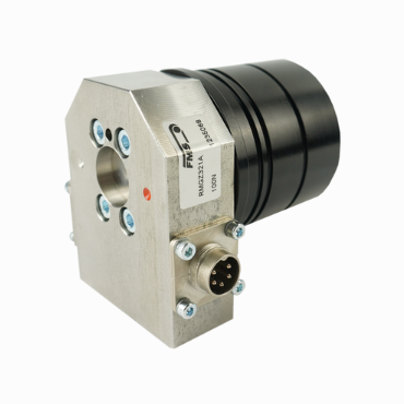
FMS RMGZ400 force sensor for stationary pulley tension measurement on wire and cable machinery
Fixed pointForce sensorWith amplifier

Stationary force sensors + amplifiers

A stationary force sensor measures the force on a fixed pulley. With the correct geometry and amplifier, the system reports material tension at locations such as payoff, take-up, drawing, extrusion, and rewinding.

Best for
A stationary pulley where one material path needs continuous tension visibility
System
Force sensor plus the appropriate measuring amplifier, display, or PLC interface
Limit
Final sizing depends on tension, wrap angle, pulley weight, speed, and installation geometry
Use the tension selector
FMS RMGZ300 rotating force sensor for individual strand tension measurement
RotatingIndividual strandsRMGZ200 / 300

Strander and twister force sensors

RMGZ200 and RMGZ300 sensors measure individual wire or strand tension on rotating planetary and tubular stranders, bunchers, and twisters.

Best for
Finding strand-to-strand imbalance that a total line-tension value can hide
Measures
Individual strand tension at the rotating machine section
Limit
The complete system also needs suitable telemetry, power, mounting, and data handling
Build the rotating tension path
FMS RTM X42 modular wireless system for monitoring tension on multiple strands
WirelessMulti-channelReporting

RTM X42 tension monitoring

RTM X42 is a modular wireless system that carries tension readings from many strands off the rotating machine. It can send data to the PLC and support displays, limits, recipes, reports, and optional brake control.

Best for
Multi-bay or higher-channel-count stranders that need a scalable system
Provides
Wireless tension data, limits, trends, PLC connectivity, and optional Control Center
Limit
Channel count, machine layout, rotating power, data, and reporting requirements must be mapped
Explore RTM X42 monitoring
02

Telemetry, automatic control & machine safety

FMS RTM MP Plus system transmitting encoder, digital, analog, and force-sensor signals wirelessly
Wireless signalsRotating machinerySlip-ring alternative

RTM MP Plus signal transmission

RTM MP Plus is a compact wireless link for sending encoder, on/off, analog, and limited force-sensor signals from rotating equipment to stationary controls.

Best for
Buncher and twister retrofits where slip-ring signal transmission is impractical
Transmits
Encoder, digital, analog, and force-sensor signals in one rotating-machine path
Limit
It is not a substitute for a full multi-channel RTM X42 tension-monitoring architecture
Check the telemetry path
FMS RTM X42 Brake Control system for automatic closed-loop strand tension control
Closed loopBrake controlAutomatic adjustment

RTM X42.BC brake control

Adds automatic payoff-brake adjustment to an RTM X42 system so measured strand tension can be maintained around a target value during production.

Best for
Cage and tubular stranders using compatible rope or belt brake arrangements
Controls
Individual payoff brake actuators using measured strand-tension feedback
Limit
Requires a full mechanical, controls, safety, channel, and brake-force review
Explore closed-loop brake control
FMS cradleGUARD receiver and transmitter modules for wireless cradle fault monitoring
Machine safetyWireless faultsCradle monitoring

FMS cradleGUARD

Wireless monitoring for wire breaks, pintle locks, tilt switches, and related cradle-level signals, with clear fault identification at the machine controls.

Best for
Faster fault diagnosis and reduced reliance on maintenance-intensive slip rings
Monitors
Discrete safety and process signals from individual rotating cradles
Limit
cradleGUARD does not measure or control wire tension
Review cradle monitoring fit
Process-specific pathways

Built around the line you operate

A gauge that works well after a drawing die may not solve a concentricity problem on an extrusion line or an individual-strand imbalance on a rotating cage.

Wire drawing & bare conductor

Monitor diameter and tension before coating, plating, insulation, or downstream processing. Encoder-linked profiles and FFT can help trace repeating mechanical variation.

Use the measurement selector →

Insulation & jacketing extrusion

Combine OD and ovality measurement with ultrasonic wall and concentricity, 3D surface inspection, alarms, reporting, and process feedback where required.

Use the measurement selector →

Data cable, pairs & multiple strands

For parallel strands, use a compatible laser micrometer, a horizontal multistrand roller guide or custom spaced fixture, and Total Vu Multi-Strand software. For twisted pairs and assembled data cable, use multiple axes, Max/Min, or FFT when average OD alone does not describe the outside envelope.

Review advanced cable measurement →

Taping & shielding

Measure an incoming twisted pair or cable before the first taping head, between tandem heads to isolate first-layer buildup, and after the final head to verify finished OD and ovality.

Check the taping measurement path →

Stranding, bunching & cabling

Measure individual strand tension, transmit rotating-machine data, document recipes, or add automatic brake control when total line tension leaves important blind spots.

Explore strander tension systems →

Fiber, fine wire & finished-part QA

Use multi-strand measurement, controlled BenchLinc inspection, or automated Metron profiling for small products, cut components, incoming inspection, and R&D.

Use the measurement selector →
Buyer comparison

Compare measurement and tension options

These tables show the likely starting point. Final selection still depends on the product, machine layout, required accuracy and repeatability, tension geometry, controls, and data needs.

Measurement and inspection systems

Use this table to separate direct sensor capabilities from software analysis and controlled offline inspection.

Swipe horizontally to compare all measurement systems.

Preliminary comparison of wire and cable measurement systems
SystemPrimary workflowOD / ovalityWall / concentricity3D surfaceAdvanced geometryProfile / QABest fit
Laser micrometerInline or benchYesNo — external dimensions onlyNo — flags size changes onlyWith Total Vu optionsWith encoder or bench setupFast non-contact OD and ovality measurement
UltraGaugeInline extrusionPair with laser ODYes — construction dependentNoNot the primary purposeLength profile with encoderInsulation or jacket wall and concentricity
FlawSenseInline or controlled offlineYesNoYes — raised and lowered flawsEvent and profile analysisWith encoder or motionOD, ovality, and 3D surface inspection
Total Vu applicationsSoftware layerUses connected gaugesUses connected gaugesWith FlawSenseFFT, Max / Min, Multi-StrandTrends, recipes, reports, controlTurning measurement data into process decisions
BenchLinc ODOffline benchYesNoNoMulti-angle / TIR workflowAutomated sample rotationRepeatable sample and finished-product QA
MetronOffline automated scanYesNo with laser-only configurationWith selected inspection technologyLength-indexed external profileAutomated feed and rotationCut products requiring complete profile inspection

Wall note: a laser micrometer does not directly measure insulation or jacket wall. Two OD stations can estimate the material added by comparing the bare conductor diameter with the finished diameter. This is an indirect calculation; direct wall and concentricity require compatible ultrasonic or other wall-measurement technology.

Surface note: a micrometer can flag a localized OD change but does not create a 3D surface map. FlawSense adds laser triangulation for raised and lowered surface anomalies.

FFT / SRL note: fast Fourier transform (FFT) analysis can reveal repeating geometry linked to process mechanics and structural return loss (SRL) risk. It does not perform the electrical SRL test or replace cable certification.

Tension, telemetry, control, and safety systems

Not every wireless system measures tension, and not every tension sensor is designed for a rotating machine.

Swipe horizontally to compare all tension-system layers.

Preliminary comparison of wire and cable tension and telemetry systems
SystemFixed machine pointRotating sectionMeasures tensionWirelessReporting / controlBest fit
Stationary force sensor + amplifierYesNoYesNormally wiredLocal, analog, or networked outputPayoff, take-up, drawing, extrusion, and rewinding
RMGZ200 / RMGZ300Not the primary useYesYes — individual strandRequires telemetry pathDepends on complete systemPlanetary or tubular strander, buncher, and twister
RTM X42NoYesWith rotating force sensorsYesPLC, limits, trends, recipes, reportsScalable multi-channel strand-tension monitoring
RTM MP PlusNoYesCan carry limited force-sensor signalsYesSignals to existing controlsCompact mixed-signal transmission and slip-ring retrofit
RTM X42.BCNoYesUses RTM X42 tension dataYesClosed-loop brake controlAutomatic tension adjustment on compatible stranders
FMS cradleGUARDNoCradle signalsNoYesFault display and relay / PLC outputsWire-break, pintle-lock, tilt, and cradle fault monitoring

Sizing note: the force sensor is sized from the actual force on its pulley, not material tension alone. That force also changes with wrap angle, entry and exit direction, pulley weight, and acceleration. Final sizing requires the machine layout.

Rotating-system note: a complete rotating-machine system may include force sensors, measuring electronics, wireless transmitters and receivers, a PLC or operator display, and—when required—brake actuators or separate safety monitoring.

Software and integration

The sensor is only the first layer

Operators need a clear display. Engineers need trends and diagnostics. Quality teams may need recipes and reports. Controls teams need reliable signals and defined ownership of the data.

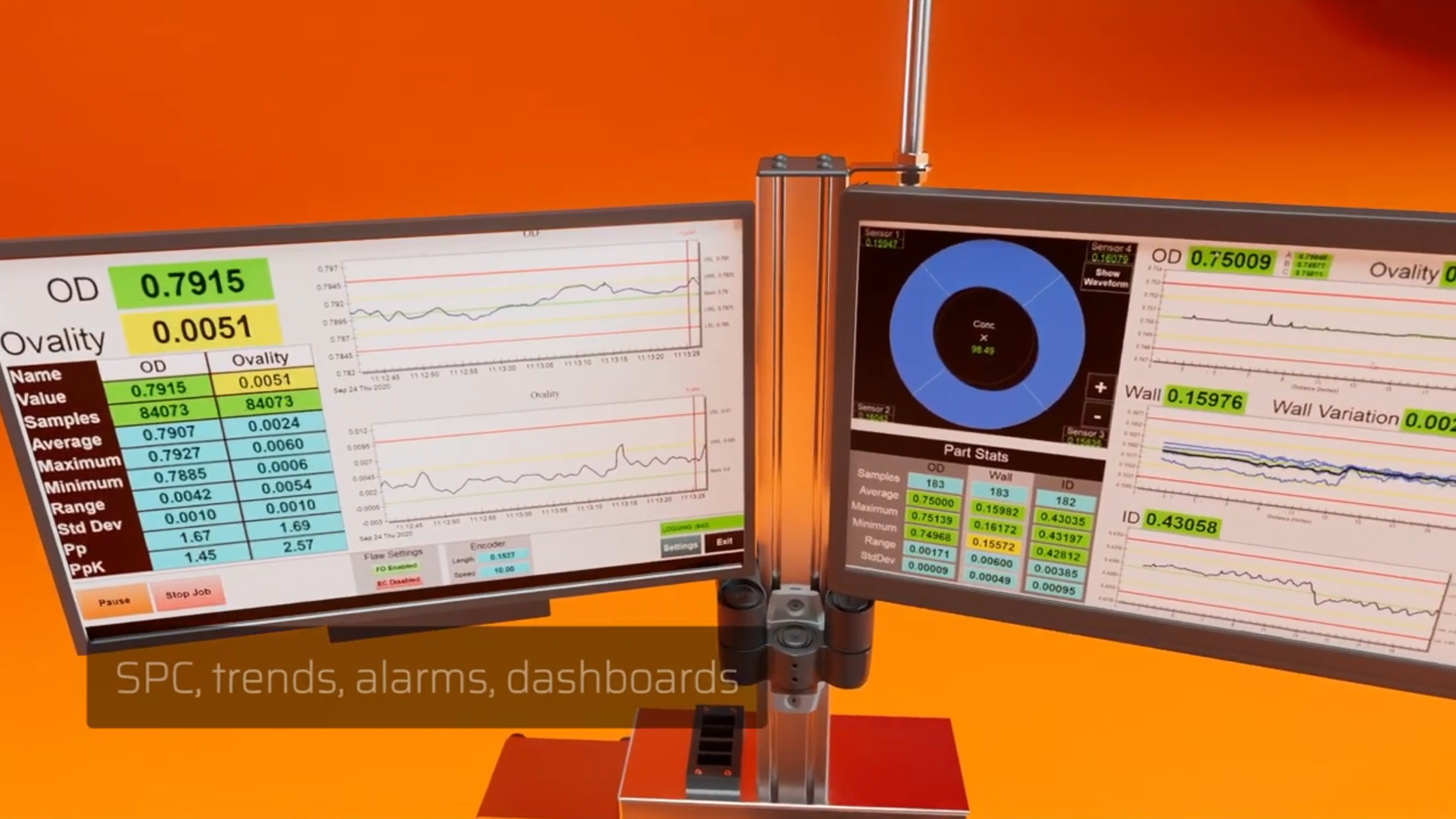
LaserLinc Total Vu interface displaying wire and cable measurement data

LaserLinc Total Vu

Brings laser, ultrasonic, and FlawSense measurements into a configurable production or QA interface.

  • Live values, trends, alarms, saved setups, and tolerance checks
  • Fast Fourier transform (FFT), Max/Min, Multi-Strand, statistical process control (SPC), reports, and saved production data
  • PLC signals, OPC UA connection to plant data systems, and optional closed-loop control
Explore Total Vu capabilities →
FMS RTM X42 Control Center for strander tension visualization and reporting

FMS Control Center and machine integration

Turns individual strand-tension readings into an operator display, quality record, PLC signal, or automatic control input.

  • Individual strand values, limits, trends, and fault visibility
  • Recipes and production documentation for repeatable setups
  • PLC integration and the system layer required for X42 brake control
Explore strander monitoring architecture →
Applications support

Define the line before selecting the hardware

Gauge Advisor matches the product requirements to the actual machine layout, measurement point, pulley geometry, controls, data needs, and support plan.

Matt’s support during his recent visit, as well as his follow-up, has been impeccable. Looking forward to ordering many more systems on our machines.
Omnitek Cable — Sherwood, Oregon
01

Share the product and machine

Provide the cable construction, dimensions, tolerances, speed, process stage, machine type, measurement or tension problem, and available drawings or photos.

02

Define the complete system

We separate the sensing hardware from the software, wireless transmission, sample handling, PLC connections, reporting, and control needs. We also identify assumptions that require a calculation or sample test.

03

Configure and support the system

Once the path is confirmed, we can coordinate quotations, mechanical and controls review, installation planning, training, startup, and ongoing troubleshooting.

Faster application review

What should you send us?

You do not need a finished specification. A drawing, machine sketch, product range, and short description of the problem are usually enough to identify the first questions.

  • Product construction and materials
  • Minimum and maximum OD and tolerances
  • Insulation or jacket wall and concentricity requirements
  • Process stage and normal / maximum line speed
  • Surface-defect definition and smallest relevant flaw
  • Measurement stations and available installation space
  • Minimum and maximum tension by machine position
  • Pulley diameter, weight, wrap angle, and entry / exit geometry
  • Machine type, payoffs, bays, cradles, and strand count
  • PLC, network, reporting, alarm, and control requirements
  • Drawings, machine photos, and representative samples when available
Common engineering questions

Wire and cable measurement FAQ

These answers provide a starting point. Final capability depends on the product construction, process, required accuracy and repeatability, machine geometry, and integration plan.

Which system measures wire or cable OD and ovality?
A laser micrometer measures external dimensions without touching the product. A single-axis gauge measures from one direction. A dual- or triple-axis gauge measures from two or three directions, making ovality and shape variation easier to see without depending as much on product rotation.
Can one laser micrometer measure several parallel strands?
Yes, when the strand sizes, spacing, and presentation are compatible. A horizontal multistrand roller guide or custom spaced fixture keeps the strands separated and aligned as they pass through the laser micrometer. Total Vu Multi-Strand software can then display a separate diameter measurement for each strand. This is different from measuring the combined outside envelope of a twisted or fully assembled cable, so the strand count, diameter range, spacing, speed, and guide design should be reviewed.
Where should diameter gauges go on a two-head taping line?
A gauge before the first head establishes the incoming twisted-pair or cable geometry. A gauge between the heads isolates the dimensional buildup produced by the first tape layer, and a final gauge verifies OD and ovality after the second layer. Not every line needs all three stations: a before-and-after arrangement may be sufficient when intermediate access is limited or only finished dimensions matter. These stations measure external geometry and dimensional buildup; they do not directly measure one-sided tape thickness, overlap, or adhesion.
Can a laser micrometer measure insulation wall thickness?
Not directly. A laser micrometer measures external diameter. Two OD stations can calculate dimensional buildup by comparing the bare conductor with the coated product, but direct wall thickness and concentricity require a compatible ultrasonic or other wall-measurement method.
What is the difference between concentricity and ovality?
Ovality describes how much the outside shape differs from round. Concentricity describes how centered one layer or conductor is inside another. A cable can have a stable OD and still have uneven insulation wall if the conductor is off-center.
When is FlawSense needed instead of a laser micrometer?
A laser micrometer is the right tool for external dimensions and can flag defects that create a measurable OD change. FlawSense is used when the application needs a 3D surface map of localized raised or lowered flaws that may not produce a reliable overall diameter change.
Does FFT software directly measure structural return loss?
No. FFT analyzes repeating dimensional patterns in measurement data. Those patterns can identify process mechanics or geometry associated with SRL risk, but FFT does not directly perform the electrical return-loss test or replace cable certification.
Why measure individual strand tension instead of total tension?
A correct total value can hide an uneven distribution. Some strands may be too tight while others are too loose. Individual sensors show the balance across the strand bundle so the source of instability, breakage, or geometry variation is easier to identify.
What is the difference between RTM X42 and RTM MP Plus?
RTM X42 is designed to monitor tension across many individual strands. It can support displays, limits, reports, PLC integration, and optional brake control. RTM MP Plus sends a smaller mix of encoder, on/off, analog, and limited force-sensor signals from rotating equipment to stationary controls.
Does tension monitoring automatically control tension?
No. A monitoring system measures and reports tension. Automatic adjustment requires a compatible control system, brake or drive hardware, machine safeguards, and a reviewed control strategy.
What information is needed to size a wire tension sensor?
Start with minimum and maximum material tension, pulley diameter and weight, wrap angle, entry and exit geometry, speed, mounting space, environment, and required output. For rotating machinery, also provide the machine type, payoffs, bays, cradles, strand count, available power, PLC, reporting, and control requirements.
Can the systems connect to an existing PLC or quality system?
Often, yes. The available path depends on the selected LaserLinc or FMS hardware and software. Define whether the plant needs analog signals, an industrial network, OPC UA, recipes, reports, alarms, raw data, closed-loop control, or enterprise connectivity during application review.
Application-first support

Have a cable construction, line drawing, or tension problem?

Share the product and machine details. We will identify whether the issue involves product geometry, surface inspection, tension, wireless transmission, software, or control—and recommend the few technologies worth reviewing.

Gauge Advisor is an authorized LaserLinc and FMS sales & support partner. Final recommendations may require drawings, machine review, calculations, and testing with representative products.

Interactive measurement selector

Build your measurement profile

Answer five guided questions to narrow the inline, bench, scanning, or inspection paths worth reviewing.

5 guided questionsAbout 2 minutes
Gauge Advisor interactive tool

Wire & Cable Measurement Selector

Open standalone

Gauge Advisor Tool

Wire & Cable Measurement System Selector

Start with what you need to measure, then tell us where the measurement happens, what the product looks like in the gauge, and how you plan to use the data.

How this tool works: choose everything you need to measure or inspect, then answer a few practical questions about the process and product. It is normal to combine measurements. For example: outside diameter + roundness, outside diameter + wall thickness + centering, or diameter + surface and FFT/SRL analysis.

1What do you need to measure or inspect?

Choose everything that applies. A single project can include diameter, roundness, insulation or jacket thickness, centering, surface inspection, repeating-diameter analysis, or a bench runout check.

✓ Choose more than one when the project needs it
Choose one or more needs above. Common combinations include outside diameter + roundness, outside diameter + wall thickness + centering, surface or lump inspection + diameter, and diameter + FFT/SRL.

2Where will you measure the product?

Choose the process that best matches the line. We will show only the measurement-point questions that apply.

3Where should the extrusion line be measured?

Choose whether you need to measure the incoming bare conductor, the hot coating just after the die, the cooled finished product, or more than one location.

3How many places should measure diameter?

Choose how many points on the line need an outside-diameter check, such as after each taper, wrapping head, cabling step, or process zone.

3Where should the drawing line be measured?

Most drawing lines only need a diameter check after the final die. Choose the two-point option when you also need to verify incoming wire or compare the product before and after drawing.

3How will the product pass through the gauge?

Tell us whether the gauge sees one object, several separated objects, or one twisted or finished outside profile.

4Line speed and automatic control

Shown only for production-line measurements. Line speed can affect the scan rate, and automatic control means the measurement will help adjust the process.

5What size product will each gauge see?

Enter the smallest and largest outside diameter expected at every active measurement point. We use the range to remove gauges that are too small or unnecessarily large. Wall-thickness fields appear only where a coating, insulation, jacket, or layer review applies.

6What does the product surface look like?

Shown only for surface or lump/neckdown inspection. The material finish affects how easily an optical system can see a defect and whether sample testing is needed.

6How will the measurement be used?

Tell us how important the measurement is and whether you need a live reading, saved data, reports, or a connection to the plant controls.

Your recommended starting system

The cards below explain what fits the answers you entered, the key sizing details, and anything that still needs to be confirmed.

Detailed recommendations and sizing notes

Review each equipment role, range note, and item that still needs confirmation.

Your preliminary equipment path is ready.

Use the recommendation as a practical starting point. Final placement, guides, communications, and control details should be confirmed around the actual line.

Your criteria and preliminary recommendation will be added to the contact form. You only need to enter your name and work email, and everything remains editable.

Why Engineers Choose LaserLinc

Four-year coverage on most LaserLinc hardware
Quick Remote & Phone Support
Application Expertise
Scalable Measurement Tools

Gauge Advisor provides authorized LaserLinc sales and applications support. Equipment guidance, quotations, and project coordination are included in the represented-equipment sales process at no separate consulting charge.

Interactive tension selector

Build your tension-system profile

Answer five guided questions to narrow the sensing, telemetry, control, or cradle-monitoring paths worth reviewing.

5 guided questionsAbout 2 minutes
Gauge Advisor interactive tool

Wire & Cable Tension Equipment Selector