Wire & Cable Measurement System Selector

Find the right measurement system for your wire, cable, fiber, or extrusion application in less than 60 seconds.

1

Select Your Goals

Choose what you need to measure: OD, Ovality, Insulation Wall, Concentricity, Surface Flaws, FFT/SRL, or TIR.

2

Define Your Process

Specify whether the application is drawing, extrusion, insulation, jacketing, taping, cabling, or bench/lab QA.

3

Describe the Product

Enter your OD range and identify whether the product is a single wire, fiber, twisted pair, multi-strand setup, or finished cable.

Wire and cable measurement depends on the process, product construction, diameter range, surface condition, and how the part is presented to the gauge. This selector helps match your application to the right LaserLinc measurement workflow for inline production, bench inspection, full-length scanning, or advanced software analysis.

Official LaserLinc measurement technology partner for wire and cable applications

Official Measurement Technology Partner

Find the Right System for Your Process

Gauge Advisor Tool

Wire & Cable Measurement System Selector

Start with the measurement goal, then narrow the recommendation by process, strand presentation, product size, line speed, and data requirements.

How this tool works: choose what needs to be measured first, then refine the recommendation by process and handling conditions. You can select more than one measurement, which is common for wire and cable applications such as OD + ovality, OD + insulation/jacket wall + concentricity, surface inspection or lump/neckdown detection + FFT/SRL, or OD + TIR/runout.

1What do you need to measure?

Select all that apply. The selector can combine dimensional measurement, insulation/jacket wall review, surface inspection, lump/neckdown detection, FFT/SRL analysis, and lab TIR/runout checks.

✓ You can select more than one option
Select one or more measurement needs above. Common combinations include OD + ovality, OD + insulation/jacket wall + concentricity, surface defects or lumps/neckdowns + OD, and OD + FFT/SRL.

2What process are you running?

Choose the process that best matches how the product will be measured.

3Extrusion measurement location

Used only for insulation, jacketing, and extrusion lines. This helps decide whether the line needs a bare wire/core gauge before the extruder, a coated-product gauge after extrusion, or a multi-station setup.

3Measurement stations

Used for taping, wrapping, and cabling lines where the product may be measured after one or more tapers, wrapping heads, cabling steps, or process zones.

3Wire drawing measurement point

Most wire drawing applications use one OD measurement point after the final die. Use the optional incoming + final comparison only when the application needs to compare wire size before and after drawing.

3Product presentation

This helps determine whether the product should be measured as one overall profile or as multiple separated wires, fibers, or conductors.

4Line speed and process control

Used for inline drawing, extrusion, taping, wrapping, and cabling paths. Extrusion applications can also use the hot/cold location question above.

5Product size

OD filters compatible micrometer, FlawSense, and BenchLincOD paths. Use minimum and maximum values because wire and cable products are usually specified as a range. For extrusion, taping/wrapping/cabling, and optional before/after wire drawing checks, each measurement station gets its own min/max OD so the gauge can be selected correctly for that station. Wall thickness is entered only for coated/jacketed stations. For taping, wrapping, and cabling, layer/wall values are treated as application-review context rather than an automatic ultrasonic selection.

6Surface characteristics

Used when surface defects or lump/neckdown detection is selected. Surface condition affects FlawSense model review, fixturing, lighting, and sample-testing confidence.

6Confidence and data

This separates basic OD checks from applications that need stronger shape visibility, process control, defect review, or saved analysis data.

Recommended system path

These recommendations are based on the process, product size, measurement goals, and data needs selected above.

Application review recommended

Wire and cable measurement systems are often configured around product presentation, guides, communication needs, and control loops.

Measurement first

The tool starts with the measurement target because OD, ovality, insulation/jacket wall, surface inspection, FFT/SRL, and TIR often require different system configurations.

Process second

Wire drawing, extrusion, taping, cabling, and lab measurement have different line speeds, handling conditions, fixture needs, and data requirements.

Product presentation note

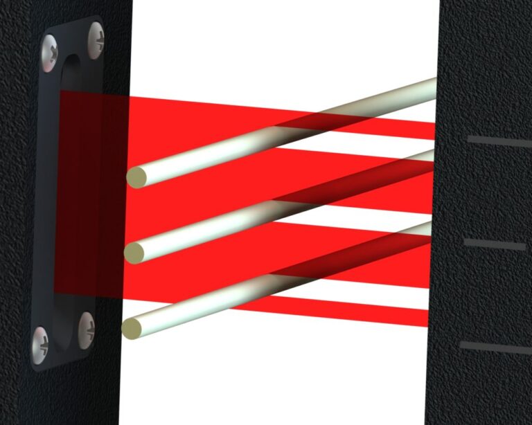
Multi-strand measurement means multiple separated wires, fibers, or conductors are visible individually in the measurement field. Twisted pairs, stranded products, and jacketed assemblies are usually measured as one outside profile, often with Max/Min, FFT/SRL, or shape analysis as needed.

Insulation wall note

Insulation or jacket wall measurement is application-dependent. The selector can flag a possible ultrasonic path, but material, construction, and thickness should be reviewed before quoting.

Wire & Cable Measurement Systems Overview

LaserLinc Measurement Technologies at a Glance

The selector above recommends the best starting approach. Below is a visual reference of the primary LaserLinc measurement systems used for wire drawing, insulation, jacketing, taping, cabling, fiber optics, and lab inspection applications.

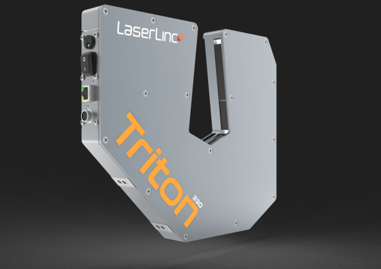
LaserLinc laser micrometer for wire and cable OD and ovality measurement

Inline / Bench Standard

Laser Micrometers

Non-contact laser micrometers for OD, diameter, and ovality measurement in wire, cable, fiber, insulation, jacketing, and extrusion processes. Single, dual, and triple-axis configurations are available depending on the required diameter range, shape visibility, and process confidence.

LaserLinc UltraGauge ultrasonic insulation wall thickness and concentricity measurement system

Insulation / Jacket Wall

UltraGauge Ultrasonic

Ultrasonic measurement technology for insulation or jacket wall thickness applications where the material, wall thickness, conductor/core construction, and transducer selection are suitable. When paired with OD measurement, UltraGauge can support wall, ID, and concentricity/eccentricity calculations.

LaserLinc BenchLincOD bench system for wire cable diameter and TIR measurement

Bench / Lab Diameter

BenchLincOD

Bench system for operator-fed wire, cable, fiber, or component samples where controlled diameter measurement and total indicated runout, or TIR, are needed. The spring-loaded chuck holds the sample while the micrometer checks diameter from multiple angles.

LaserLinc Metron automated OD scanning system for cut-to-length wire cable and component inspection

Full-Length Scan

Metron Horizontal / Vertical

Automated scanning system for cut-to-length wire, cable, guidewire, mandrel, rod, fiber, or component inspection. Metron is useful when a single spot check is not enough and the full part needs to be reviewed for OD variation, taper, bumps, neckdowns, or length-based profile changes.

LaserLinc FlawSense surface defect detection system for wire cable fiber and extrusion applications

Surface / Shape Inspection

FlawSense

Laser line triangulation system for detecting non-dimensional surface defects such as cracks, slits, pits, scratches, lumps, bumps, or braid-related issues while also supporting OD and ovality measurement for many wire, cable, fiber, and extrusion applications.

LaserLinc multi-strand measurement for separated wires fibers and conductors

Fiber / Multi-Conductor

Multi-Strand Measurement

Used when multiple separated wires, fibers, or conductors need to be measured individually within the measurement field. This is commonly relevant for fiber optics, ribbon fiber, parallel conductors, or lab fixtures where the strands can be physically separated.

Data, Display & Software Options

Choose How Measurement Data Is Used

After the measurement system is selected, the next decision is how the data should be viewed, saved, reported, analyzed, or connected to production systems.

LaserLinc SmartLinc Display for wire and cable laser micrometer spot checks

Simple Spot Checks

SmartLinc Display

A compact display option for laser micrometer applications where basic diameter and ovality readings are needed without trend charts, SPC, reporting, or data export.

LaserLinc SmartLinc processor for wire and cable measurement data output and communication protocols

Raw Data / Integration

SmartLinc Processor

Used when measurement data needs to be sent directly into another system using industrial communication or data-output protocols. Best for advanced integration workflows.

LaserLinc Total Vu software for wire and cable measurement visualization SPC reporting and data storage

Visualization / SPC / Reports

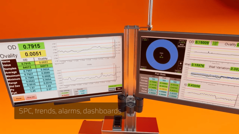
Total Vu Software

The most flexible option for most wire and cable applications. Total Vu provides Windows PC-based visualization, trend charts, SPC, recipes, custom reports, saved data, and a customizable measurement interface.

LaserLinc FFT and SRL analysis software for wire and cable periodic diameter variation

Periodic Variation

FFT / SRL Analysis

Software option for identifying repeating diameter variation, lay length-related patterns, or periodic process issues caused by screws, belts, pullers, capstans, rotating tooling, taping, twisting, or stranding.

LaserLinc Max Min software option for twisted pair stranded wire and cable diameter peaks and valleys

Twisted / Irregular Profiles

Max / Min Diameter Software

Software option for twisted pair, stranded wire, braided products, or irregular cable profiles where average OD alone may hide important peaks and valleys. Max / Min helps identify the real outside envelope of the product.

Selection note: SmartLinc Display is only intended for laser micrometer spot-check applications. UltraGauge, Metron, FlawSense, BenchLincOD, FFT/SRL analysis, Max/Min software, multi-strand applications, and most inline production systems typically use Total Vu for visualization, recipes, SPC, reporting, and saved measurement data.

Next Step After the Selector

Match the measurement system to the real wire or cable application

The selector gives you a strong starting point. Final system selection should still consider the product construction, process type, diameter range, material behavior, line speed, data needs, and whether the product is measured inline, at the bench, or as a cut-to-length component.

Why This Matters

The wrong measurement approach can hide the real process issue

In wire and cable production, the right measurement system depends on more than diameter alone. Drawing, extrusion, jacketing, taping, twisting, cabling, and lab inspection can each create different measurement challenges.

Missed surface issues: OD measurement alone may not catch cracks, slits, pits, scratches, lumps, bumps, braid issues, or other defects that do not create a reliable diameter change.

Profile variation: Twisted pair, stranded wire, braided products, and irregular cable profiles may need Max/Min, ovality, or envelope-style analysis instead of simple average OD.

Workflow mismatch: Inline extrusion, wire drawing, taping, cabling, multi-strand inspection, bench checks, and full-length cut-part scanning often require different measurement approaches.

Wire drawing

Laser micrometers are used for diameter and ovality visibility during drawing. FFT/SRL analysis can help identify repeating diameter patterns from capstans, dies, rolls, or other mechanical sources.

Extrusion / insulation / jacketing

Use laser micrometers for OD and ovality, FlawSense for surface defects, and UltraGauge ultrasonic systems when insulation or jacket wall measurement is feasible for the material and construction.

Taping / twisting / cabling

Twisted, wrapped, braided, or stranded products may require Max/Min, FFT/SRL, or full outside-envelope visibility instead of only average diameter.

Bench / lab / cut parts

BenchLincOD is used for diameter and TIR checks, while Metron is used when cut-to-length wire, cable, fiber, mandrels, rods, or components need full-length OD profile inspection.

Data Layer

Decide how the measurement data should be used

After choosing the measurement system, the next decision is how the data should be viewed, saved, analyzed, reported, or connected to another system.

Spot Checks

SmartLinc Display

Best for simple laser micrometer spot checks where live diameter and ovality values are enough.

Raw Data Output

SmartLinc Processor

Used when measurement data needs to be exported directly to a PLC, SCADA, MES, or other plant system.

Most Common

Total Vu Software

The most flexible option for charts, SPC, recipes, reports, saved data, custom screens, FFT/SRL, Max/Min analysis, and full measurement visibility.

Common Questions

Quick answers before application review

Can a laser micrometer measure insulation wall thickness?

No. Laser micrometers measure outside dimensions such as OD and ovality. Insulation or jacket wall thickness typically requires ultrasonic measurement, and feasibility depends on material, wall thickness, conductor/core construction, and transducer selection.

When is multi-strand measurement realistic?

Multi-strand measurement is realistic when multiple wires, fibers, or conductors are physically separated in the measurement field. For twisted pair, stranded wire, or bundled cable, the system usually measures the outside profile or envelope instead of each strand individually.

When are FFT/SRL or Max/Min software options useful?

FFT/SRL is useful when diameter variation repeats at a consistent frequency or lay length. Max/Min is useful for twisted, stranded, braided, or irregular profiles where average OD alone may hide important peaks and valleys.

Ready for the Next Step?

Use your selector results to start the application review

Whether you are measuring wire diameter during drawing, monitoring insulation or jacket OD, reviewing periodic variation, inspecting multiple fibers, scanning cut-to-length components, or detecting surface defects, Gauge Advisor can help match the application to the right LaserLinc measurement workflow.