Updated August 21, 2026
Wire and cable measurement is not one gauge at the end of an extrusion line. A complete quality architecture may need to measure the incoming conductor, hot insulation, cooled outside diameter, individual wall sections, concentricity, surface defects, periodic geometry, strand tension, and finished-product profile. The right system begins with the physical characteristic that controls product performance, then places the appropriate sensor where the data can still improve the process.
Connected process path: Combine dimensional, wall, defect, and data tools with tension control when drawing, payout, stranding, taping, or take-up force changes the finished cable.
Related next steps: wire and cable measurement systems, wire and cable measurement selector, laser micrometers, UltraGauge transducer selector, and wire and cable tension selector.
Eight wire and cable measurement problems that require different signals
“Diameter control” is often used as a shorthand for the entire quality system. That is convenient, but incomplete. Define which of the following characteristics actually controls the drawing, specification, electrical performance, material usage, or customer acceptance.
Diameter, ovality, width, height, flatness, and outside profile on round, oval, flat, or irregular products.
Individual wall sections, minimum wall, average wall, eccentricity, concentricity, and calculated internal geometry.
Pits, scratches, cracks, blisters, raised material, recessed material, braid events, and full-contour surface topography.
Short dimensional events, twisted-pair peaks and valleys, local diameter excursions, and irregular profile limits.
Repeating diameter or concentricity patterns that can create electrical-performance risk in data and coaxial cable.
Simultaneous outside measurement of multiple conductors or strands when product spacing and field geometry permit.
Bench inspection, length-positioned profiles, TIR, tapers, transitions, and documented spool or sample results.
Payoff, take-up, capstan, dancer, and individual strand tension. This is an adjacent FMS process variable, not a LaserLinc dimensional measurand.
A practical project often combines several layers. A THHN line may need hot and cooled OD, individual nylon and PVC layer information, surface-defect detection, SPC, and material-usage control. A data-cable line may add Max/Min geometry, FFT analysis, and an electrical correlation plan. A stranding operation may require FMS tension telemetry in addition to LaserLinc dimensional inspection. The Wire & Cable Measurement System Selector provides a measurement-only starting path, while the Wire & Cable Tension Equipment Selector handles stationary and rotating tension applications separately.
Where measurement belongs across a wire or cable process
Click each stage to see what can be learned there and what can make the reading misleading. The best measurement location is not simply the first open section of machine frame. It is the location where the product is visible, stable, and still close enough to the process variable that can correct the condition.
1. Incoming conductor: verify the foundation before adding insulation
Conductor diameter, shape, cleanliness, temperature, and surface condition affect every downstream layer. Measuring the incoming product helps separate a conductor problem from an extrusion problem and can support bare-to-coated calculations when the two stations are appropriately synchronized.
- Confirm whether the conductor is round, oval, flat, stranded, or moving laterally.
- Review drawing-die condition, payoff tension, vibration, temperature, and surface contamination.
- Use the same time base when comparing bare and coated measurements.
Build a preliminary wire and cable measurement architecture
Select every measurement objective that applies, then add the process, product presentation, line position, data requirement, and approximate size. The output is a preliminary system path, not a final quotation. Exact model selection still requires tolerances, speed, material, optical condition, installation space, and representative samples.
1. Select the measurement objectives
2. Add the application context
Match the wire or cable application to the measurement stack
Search by product, process, defect, or technology. The starting architecture is deliberately broader than a model number because line speed, range, material, tolerance, environment, and the required data response all affect final selection.
| Application | What should be measured | Starting architecture | Important checks and next resource |
|---|---|---|---|
Bare wire after drawing Drawing | Diameter, ovality, die wear, short dimensional events, and stability by spool or run. | Axion or Triton laser micrometer selected for size, shape, speed, and axis coverage; Total Vu for trends, SPC, alarms, and reports. | Control vibration, wire whip, temperature, coolant, and guide position. Use the laser-axis guide. |
Magnet wire or coated conductor Thin Coating | Bare diameter, coated diameter, coating build, outside defects, and process drift. | Pre-coat and post-coat laser stations for directional coating-build calculations; add surface inspection if the reject is a pit, blister, scrape, or coating ridge. | Two-station subtraction gives average radial build only under the defined geometry and synchronization. It does not directly prove individual wall distribution or adhesion. |
Single-conductor insulation extrusion Extrusion | Hot and/or cooled OD, ovality, wall, concentricity, lumps, neckdowns, and final shrinkage. | Laser OD station plus UltraGauge when individual wall and concentricity matter; Total Vu for recipes and control; FlawSense when full-surface geometry is critical. | Correlate hot and cooled dimensions rather than applying an assumed shrink factor. Start with the measurement selector. |
THHN and multilayer building wire Layered Wire | Conductor position, individual insulation/jacket layers, total OD, minimum wall, concentricity, and material usage. | UltraGauge with appropriate transducer configuration and synchronized laser OD; Total Vu visualization and control; cooled OD or surface station as required. | Layer interfaces, material acoustic response, water path, line speed, and recipe range require sample and factory review. Use the UltraGauge Transducer Selector. |
Thin-wall hookup and automotive wire Thin Wall | OD, minimum wall risk, concentricity, short neckdowns, surface damage, and startup stability. | High-speed laser micrometry with matched range; UltraGauge when wall distribution must be direct; FlawSense for critical full-surface defects. | Small product, high line speed, short defects, and product motion make measurement rate, mounting, and filtering especially important. |
Coaxial dielectric and outer jacket Coax | Diameter, eccentricity, concentricity, periodic geometry, surface defects, and relation to electrical performance. | Laser OD plus UltraGauge where acoustically feasible; Total Vu FFT tools for geometric periodicity; final electrical SRL testing remains separate. | Coordinate geometry and electrical data by spool, frequency, and time. ANSI/SCTE 03 defines a finished-cable SRL test method; inline geometry is a process diagnostic. |
LAN and high-speed data cable Data Cable | Insulated conductor OD, concentricity, pair geometry, Max/Min, periodic variation, and jacket condition. | Multiple laser and/or ultrasonic stations with Total Vu Max/Min, FFT, recipes, and synchronized data; add surface inspection where jacket flaws matter. | Do not infer finished electrical compliance from geometry alone. Use inline data to identify process signatures, then correlate to the applicable electrical test. |
Twisted pair peak and valley Twisted Pair | Maximum and minimum outside geometry, twist-related periodicity, pair balance, and local dimensional events. | Laser micrometer and Total Vu Max/Min/FFT configuration chosen for pair size, orientation, twist rate, and line speed. | Average OD can hide pair peaks and valleys. Validate the axis arrangement and reporting logic on actual twisted product. |
Multiple separated conductors or strands Multi-Strand | Individual strand diameters, strand count, spacing, and missing or oversized strands within one measurement field. | Axion single- or dual-axis multi-strand configuration where every strand remains separated and visible within the field. | Crossing, touching, overlap, vibration, and product wandering can invalidate segmentation. Submit a layout drawing and representative product. |
Optical fiber coating and buffering Fiber | Bare or coated diameter, coating geometry, concentricity where feasible, bubbles, lumps, neckdowns, and surface events. | Small-range high-speed laser micrometry; additional wall/interface or defect technology selected from actual coating and optical conditions. | Transparent layers, very small size, high speed, vibration, and short events require sample testing and a complete timing review. |
Power cable insulation and jacket Power Cable | Large OD, ovality, jacket wall, eccentricity, surface defects, layer stability, and length-positioned events. | Axion large-range one- or two-axis laser measurement; UltraGauge or another validated wall path when feasible; FlawSense for full-surface defect mapping. | Large diameter may favor fewer axes because range and mechanical access change with axis count. Review the full product envelope and installation space. |
Flat, ribbon, and rectangular extrusion Non-Round | Width, height, edge position, flatness indicators, coating build, and orientation-dependent variation. | Axion one- or two-axis arrangement aligned to the critical dimensions; additional stations or mechanics when the product can rotate. | A “diameter” gauge should not be selected as though the product were round. Define each critical silhouette dimension and orientation. |
Large hose-like cable or corrugated jacket Large Product | Outside envelope, ovality, profile, periodic features, wall where feasible, and large surface anomalies. | Large-range Axion measurement or application-specific profile architecture; separate wall and surface technology as required. | Corrugation, intentional profile, product sag, vibration, and temperature can dominate the signal. Define whether the goal is envelope, pitch, height, or defect detection. |
Full-surface cable defect inspection Flaw Detection | Pits, cracks, scratches, blisters, raised/recessed flaws, braid events, and full-contour diameter/ovality. | FlawSense laser-line triangulation with Total Vu 3D review; encoder, marker, or cut logic when defect position matters. | Color-only defects and buried internal flaws may need another method. Review the surface-defect technology guide. |
Bump, taper, transition, or local profile Feature Profile | Feature start/end, maximum/minimum size, transition length, slope, position, and local defects. | Length-encoded LaserLinc Bump & Taper or Metron-style profile workflow, selected for inline or finished-part inspection. | The drawing must define how the transition is evaluated. Position, speed, transport delay, and product handling are part of the method. |
Bench and laboratory diameter checks Offline QA | Diameter, ovality, repeatability, sample profile, correlation, and lot documentation. | BenchLinc V or OD configuration with Total Vu, appropriate fixture, calibration pins, and defined sample handling. | Match sample temperature, location, orientation, and method to the inline gauge. See the BenchLinc guide. |
Spool, cut-length, or full-length profile QA Traceable QA | Length-positioned diameter, ovality, features, defect locations, batch statistics, and acceptance status. | Controlled rewind or automated scan architecture with encoder, Total Vu records, and a defined disposition workflow. | Clarify leading/trailing exclusions, guide contact, sample tension, rewind speed, and whether the system must mark, cut, or only report. |
Cage or tubular strander tension FMS Tension | Individual strand tension, drift as bobbins empty, cradle faults, brake response, and tension balance. | FMS RTM X42 with Control Center for visualization and recipes; Brake Control for compatible closed-loop friction-brake applications; cradleGUARD for separate fault/safety signals. | Tension data complements dimensional measurement but does not replace it. Use the strander tension guide. |
Laser micrometers for diameter, shape, multiple strands, and fast process response
Laser micrometers measure the outside silhouette without touching the product. They are a strong first layer for bare wire, insulated conductor, jacketed cable, fiber, monofilament, flat profiles, and many hot or moving products. The correct axis count is determined by geometry and risk, not by the assumption that more axes are always better.
One critical outside dimension, very large product ranges, hot product, separated transmitter/receiver geometry, or limited access.
Two simultaneous dimensions, useful ovality information, flat or non-round products, and broad range coverage.
Greater angular coverage for round and elliptical products within the applicable product range.
FlawSense surface mapping when the requirement is complete visible topography rather than a few silhouette axes.
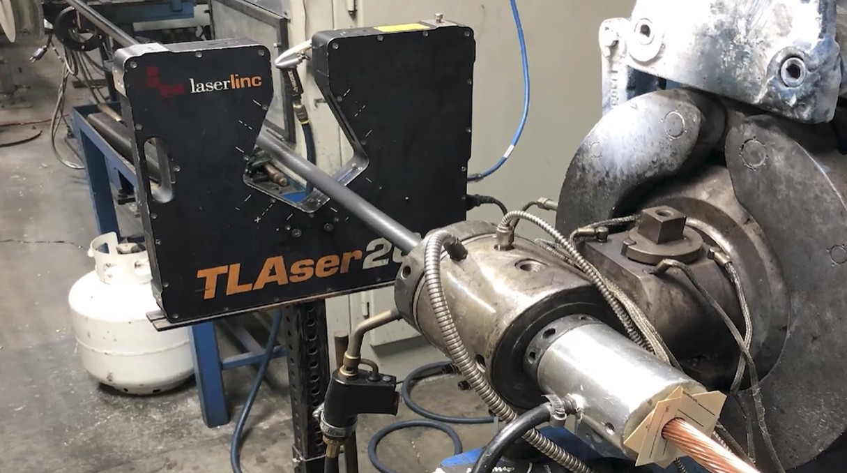
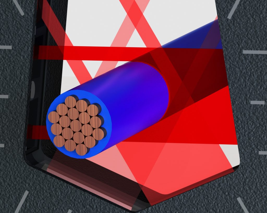
LaserLinc separates Axion one- and two-axis systems from Triton three-axis systems. Axion supports large ranges, non-round products, multiple separated strands, and split transmitter/receiver arrangements. Triton provides three-axis coverage for round and elliptical products. Published range and rate vary significantly by model, so the fastest or most highly instrumented gauge is not automatically the best fit. The Single vs Dual vs Triple Axis Laser Micrometer Guide explains the tradeoffs.
Hot measurement, cooled measurement, or both?
A hot gauge close to the die gives rapid process feedback and reduces the transport delay before correction. A cooled gauge is closer to final product state and captures cooling, shrinkage, downstream draw, and some handling effects. Two stations can be valuable when the plant needs both fast control and final dimensional confidence.
Can two laser stations calculate coating thickness?
When one station measures the bare conductor and another measures the coated product, the difference in outside size can support a directional average coating-build calculation. That can be useful for process control when the conductor remains centered enough for the intended purpose and the two data streams are synchronized. It does not directly measure individual wall sections, minimum wall, or concentricity.

Ultrasonic wall thickness, concentricity, and internal geometry
UltraGauge adds information that an outside silhouette cannot provide. Ultrasonic echoes measure wall sections and wall distribution. When synchronized with laser OD and the geometry model is appropriate, Total Vu can calculate internal dimensions and display a fuller cross-section.
Measure wall around the product rather than assuming the conductor is centered from total OD.
- Minimum and maximum wall
- Average wall
- Wall distribution
Combine wall measurements with synchronized outside geometry using the defined calculation and product model.
- Conductor offset
- Calculated internal size
- Cross-section visualization
Trend wall and OD with extruder speed, line speed, temperature, and control outputs.
- Recipes and alarms
- SPC and reports
- Qualified feedback control
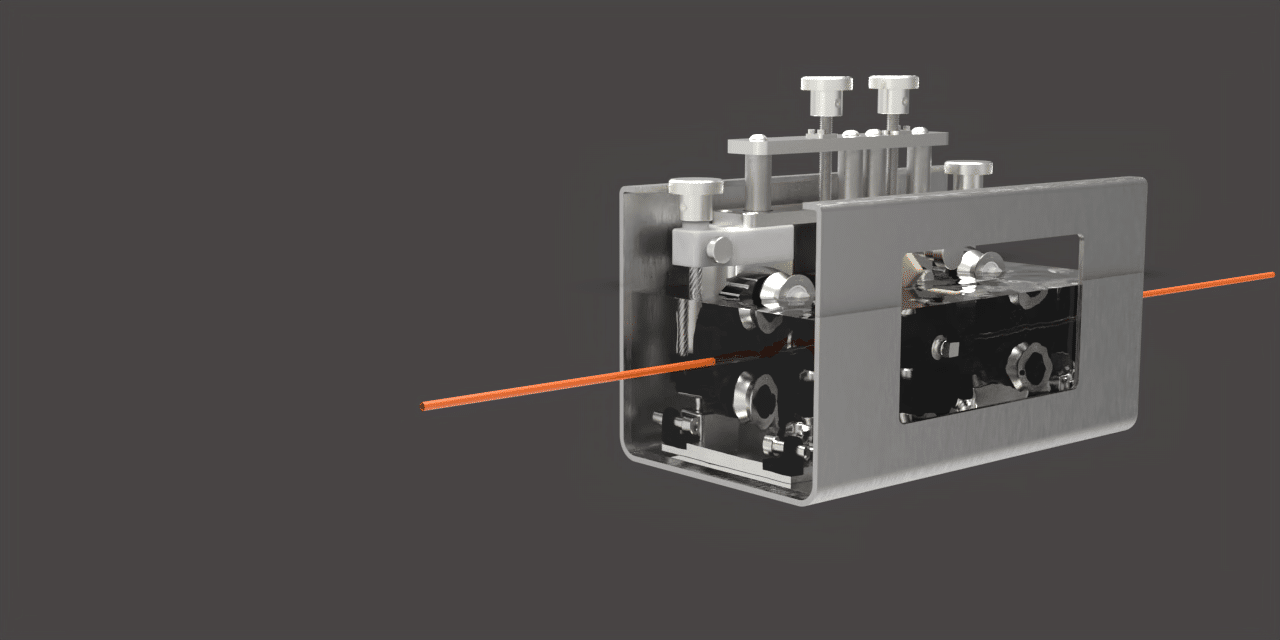

Recent LaserLinc material on THHN manufacturing highlights the value of in-process layer visualization for yield and material control. The broader lesson applies across wire and cable: if minimum wall or conductor centering controls the product, OD alone is incomplete.
Separate dimensional events from true full-surface defects
Lumps and neckdowns are important, but a narrow scratch, pit, crack, braid break, blister, or recessed feature may occupy only a small angular region and may not create a reliable average-diameter event.


Strong for full-circumference lumps, neckdowns, OD excursions, and events that affect measured silhouettes.
Strong for raised and recessed geometry around the visible contour, including pits, cracks, scratches, and braid events.
Stains, color shifts, gloss changes, and some coating skips may need controlled camera or spectral inspection.
Buried voids, insulation breakdown, pinholes, leaks, and electrical faults may require ultrasonic, spark, leak, or another method.
LaserLinc publishes FlawSense as a full-surface, laser-line triangulation system with profile rates up to 10,000 per second and product-dependent defect capability. Those figures are useful for screening, not a universal probability-of-detection guarantee. Defect width, length, slope, material, gloss, transparency, line speed, vibration, centering, normal texture, filtering, and threshold logic affect real performance. Representative good, borderline, and reject samples are essential.
The Surface Defect Detection Guide provides a deeper comparison of dimensional, three-dimensional, appearance, and internal inspection paths.
Max/Min, multi-strand, FFT, and structural return loss
Wire and cable processes contain useful information that disappears in one average-diameter value. Total Vu can analyze irregular profiles, multiple separated strands, and repeating geometric patterns when the arrangement and sampling chain match the application.


Max/Min for twisted pair and irregular geometry
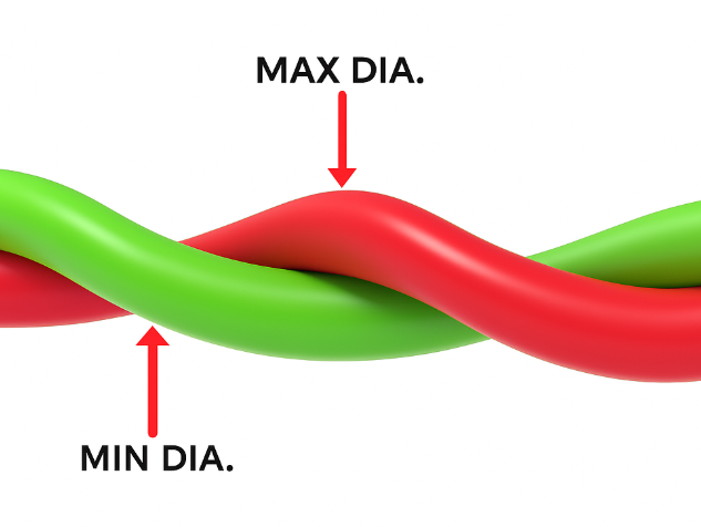
Twisted pair can present a repeating outside peak and valley as it rotates through the gauge. Reporting only the average can hide that geometry. Max/Min tools are useful when the process limit is the largest envelope, smallest valley, pair balance, or stability of the twist-related pattern.
Multi-strand measurement
A multi-strand configuration can measure several separated wires simultaneously, but every product must remain individually visible. Touching, crossing, overlap, vibration, or lateral movement can merge silhouettes and invalidate segmentation. Application review should include strand count, sizes, minimum spacing, maximum spread, line speed, and the complete product envelope.
FFT and SRL as process diagnostics
Fast Fourier Transform analysis converts a time- or length-domain geometry signal into frequency components. It can reveal repeating patterns from capstans, caterpillars, gears, cooling, pairing, extrusion, or other mechanical sources. For data and coaxial cable, those geometric frequencies can be compared with electrical test results and used to investigate structural return loss risk.
Total Vu connects sensors, process data, SPC, reporting, and control
A sensor output becomes more valuable when the operator can see it in context, the quality team can document it, and the process can respond appropriately. Total Vu is the common HMI and data layer across LaserLinc laser micrometers, UltraGauge, FlawSense, and integrated sample-inspection systems.
Collect OD, ovality, wall, concentricity, defects, Max/Min, FFT, or other characteristics at the correct location.
Align multiple gauges, speed, encoder position, process variables, recipes, and product identifiers.
Use trends, limits, SPC, frequency analysis, defect review, and reports to identify a meaningful change.
Alarm, mark, cut, isolate, adjust, or control after transport delay, actuator authority, interactions, and fail-safe behavior are understood.
Configurable displays, recipes, alarm limits, product views, and process context.
Statistics, control charts, spool or batch summaries, CSV/Excel workflows, and quality records.
Max/Min, FFT, SRL diagnostics, macros, calculated values, and multi-device relationships.
PLC, OPC, enterprise communication, feedback control, markers, cutters, and other qualified outputs.
Where FMS fits: tension can change the product without being a dimension
LaserLinc provides the dimensional, wall, defect, and process-data measurement layers described in this guide. FMS belongs in the architecture when payoff, take-up, drawing, taping, pairing, cabling, or stranding tension can change conductor position, twist, lay, stretch, jacket presentation, or finished-product consistency.


Force sensors and electronics for payoff, take-up, dancer, capstan, drawing, taping, and fixed machine points.
Individual strand-tension measurement on rotating stranders, with values sent to an existing PLC or RTM X42.CC Control Center.
RTM X42.BC Brake Control for compatible friction brakes, RTM MP for mixed rotating signals, and cradleGUARD for separate cradle faults.
FMS publishes RTM X42 for one to 42 tension channels per system, with optional Control Center visualization, recipes, and quality records. Brake Control extends compatible installations from monitoring into closed-loop adjustment of cradle friction brakes. Select the tension system independently from the dimensional system, then correlate the data when tension affects geometry or electrical performance.
Estimate the annual value of reducing finished-diameter overbuild
A small intentional OD cushion can represent substantial insulation or jacket material over a long production year. This calculator estimates the material difference between current finished OD and a lower target OD while holding conductor or core diameter constant.
Planning assumptions: continuous production at the entered average speed and hours; constant conductor/core diameter; circular cross-section; the entire entered OD reduction is genuinely avoidable; representative density and cost. The calculation excludes startup scrap, electrical yield, labor, downtime, system price, financing, and duplicated benefits. Use the Wire & Cable Measurement ROI Calculator for a broader business case.
Correlation, calibration, standards, and capability
Inline measurement should improve process visibility without becoming disconnected from the drawing or release method. Build a documented correlation between the inline system, the applicable laboratory method, and the product state being measured.
IEC 60811-201 and IEC 60811-202 describe methods for measuring insulation and non-metallic sheath thickness, while IEC 60811-203 addresses overall dimensions for circular and flat cable. Those standards provide laboratory and acceptance context. Inline laser or ultrasonic results should be correlated to the governing drawing and test method rather than assumed interchangeable without study.
NIST defines metrological traceability as a property of a result supported by a documented, unbroken calibration chain and contributing uncertainties.
Use clean standards that span the range and a defined method. The Calibration Pin Calculator helps plan practical sizes.
A repeatable system can still be biased, while an accurate average can hide poor repeatability. Review the accuracy and repeatability guide.
Cp, Cpk, Pp, and Ppk are meaningful after the process and method are stable. Use the Cpk/Ppk Calculator.
Common wire and cable measurement mistakes
Using OD as proof of wall thickness or concentricity
The conductor can move inside the insulation while outside diameter stays nearly unchanged. Direct wall or internal geometry measurement is required when minimum wall or concentricity controls acceptance.
Treating bare-to-coated subtraction as direct wall distribution
Two laser stations can estimate average radial build when geometry and timing are appropriate. They do not directly measure individual walls, minimum wall, or conductor offset.
Choosing axis count from price or habit instead of geometry
One, two, and three axes provide different angular coverage and ranges. Flat, rotating, oval, large, hot, and multi-strand products can require very different arrangements.
Comparing a hot inline reading with a cooled lab sample without correlation
Polymer shrinkage, conductor temperature, cooling, tension, draw, handling, and measurement location can create a real difference. Build the correlation by recipe instead of forcing an arbitrary offset.
Assuming average diameter will detect every short defect
Measurement rate, line speed, axis coverage, defect length, averaging, update rate, and alarm logic determine whether a short event is visible. Full-surface defects can require FlawSense.
Calling an appearance defect a three-dimensional defect
A stain, color shift, or gloss change can have no measurable height. Use a contrast- or spectrum-based method when appearance is the physical signal.
Using inline FFT or geometric SRL as final electrical certification
Inline frequency analysis diagnoses periodic manufacturing geometry and supports correlation. The finished product still requires the applicable electrical test and standard.
Ignoring water, vibration, wire whip, guides, or transparent material
Installation conditions can dominate the signal. A capable sensor can still give unstable or misleading data when the product is wet, off center, vibrating, optically unusual, or partially blocked.
Adding control before validating the measurement and transport delay
Closed-loop control needs a trusted measurement, defined actuator, adequate authority, known delay, stable tuning, limits, and fail-safe behavior.
Mixing tension, dimension, defects, and electrical performance into one pass/fail value
These signals answer different questions. A robust architecture keeps each failure mode visible, then correlates the data where the relationship is useful.
Wire and cable measurement project checklist
Providing this information early allows a faster and more accurate LaserLinc or FMS application review.
- Product and processWire, conductor, cable, fiber, hose, profile, drawing, extrusion, jacketing, pairing, stranding, rewind, or offline QA.
- Material constructionConductor/core, insulation and jacket polymers, layers, filler, foam, braid, color, transparency, reflectivity, and temperature.
- Complete size rangeMinimum and maximum OD, width, height, wall, conductor size, strand spacing, product envelope, and movement.
- SpecificationsNominal, upper/lower limits, minimum wall, concentricity, ovality formula, defect limits, electrical tests, and customer standards.
- Line conditionsNormal and maximum speed, acceleration, water, mist, coolant, heat, vibration, wire whip, tension, rotation, and straight length.
- Measurement locationBare, hot, cooling trough, cooled, after puller/capstan, rotating machine, rewind, or laboratory.
- Existing equipmentGauge make/model, controllers, PLC, HMI, encoders, markers, cutters, spark testers, electrical testers, and protocols.
- Data objectiveDisplay, alarm, SPC, report, recipe, audit trail, FFT/SRL, control, marking, cutting, MES, or OPC-UA integration.
- Samples and defectsGood, borderline, and known reject product; defect dimensions; photos; cut samples; complaint samples; and root cause.
- Commercial scopeNew line or retrofit, desired timing, installation responsibilities, training, validation support, and quotation requirements.
Related Gauge Advisor wire and cable resources
Wire and cable measurement FAQs
Is a dual-axis laser micrometer enough for wire and cable?
Often, but not automatically. Dual axis measures two simultaneous outside dimensions. Triple axis adds angular coverage for round and elliptical products, while single axis can fit one critical dimension, large products, hot applications, or split transmitter/receiver installations. Full-surface defects require a different topographic technology.
Can I calculate insulation thickness from bare and coated OD?
You can calculate a directional average radial build when conductor geometry is known, remains centered enough for the purpose, and the two measurements are synchronized. The calculation does not directly measure individual walls, minimum wall, or concentricity.
When is ultrasonics needed?
Ultrasonics is appropriate when individual wall, minimum wall, concentricity, eccentricity, or calculated internal geometry matters and the construction produces usable echoes. Feasibility depends on material, interfaces, wall range, size, water path, speed, and transducer configuration.
Can one system measure OD, wall, defects, and tension?
One HMI can integrate several LaserLinc devices, but the physical signals still require different sensors. Tension is normally a separate FMS path. The value comes from coordinating the data, not pretending one sensor measures every characteristic.
What is the difference between lump/neckdown detection and FlawSense?
Lump and neckdown logic evaluates short dimensional excursions in one or more laser-micrometer silhouettes. FlawSense maps the visible surface contour for raised and recessed features such as pits, scratches, cracks, blisters, and braid events.
Can FFT analysis predict structural return loss?
FFT can reveal periodic geometry and help correlate manufacturing frequencies with electrical-performance problems. Final SRL acceptance still requires the applicable finished-cable electrical test.
How do I select a measurement rate?
Convert the shortest event into time at maximum line speed, then review sensor rate, per-axis rate, averaging, data update, communication, alarm logic, and transport response. A high nominal rate can be undermined by heavy averaging or slow outputs.
Should the gauge be before or after the cooling trough?
A hot station gives faster process feedback. A cooled station is closer to final dimensions and includes cooling and draw effects. Many lines benefit from both.
Can transparent insulation affect laser measurement?
Yes. Clear, translucent, glossy, reflective, and optically unusual materials can challenge edge detection depending on the gauge and setup. The application may require different optical logic, improved guiding, another location, or sample testing.
How do I correlate inline and laboratory measurements?
Use the same sample locations, controlled temperature and conditioning, defined orientation, traceable standards, consistent units, documented fixture and contact force, and a planned study across the range.
Where does FMS tension measurement add value?
FMS adds value when payoff, take-up, drawing, taping, pairing, cabling, or individual strand tension can affect geometry, lay, stretch, conductor position, or stability. RTM X42 is the current rotating strander path for new projects.
What information should I send for a LaserLinc application review?
Send product type, material and layers, complete size range, tolerances, line speed, measurement location, surface condition, current gauges, data and control objectives, installation photos or drawings, and representative samples.
References and source notes
The references are collapsible to keep the cornerstone guide readable. They open automatically when printing.
Open technical references and source notes16 sources
Gauge Advisor is an authorized LaserLinc sales and applications support partner and an authorized FMS sales and applications support partner. Manufacturer sources are used for current product architecture and published capability. IEC, SCTE, and NIST provide noncompetitive standards and metrology context.
- LaserLinc, Measurement and Control Solutions. Current separation of laser micrometry, ultrasonic wall measurement, surface-defect detection, sample inspection, and process visualization.
- LaserLinc, Laser Micrometers. Current Axion and Triton categories for outside dimensions and shape.
- LaserLinc, Axion One- and Two-Axis Laser Micrometers. Non-round, large-range, split, and multi-strand context.
- LaserLinc, Laser Micrometer Datasheet. Published model ranges and rates; confirm specifications for the quoted system.
- LaserLinc, UltraGauge Ultrasonic Measurement. Wall thickness, concentricity, eccentricity, and laser-OD integration.
- LaserLinc, FlawSense Surface Defect Detection. Full-surface triangulation, 3D mapping, and published capability.
- LaserLinc, Total Vu Process Visualization. Integration, visualization, analytics, documentation, communications, and control tools.
- LaserLinc, Sample Inspection. BenchLinc and Metron offline and finished-product context.
- LaserLinc, Resource Center. Wire and cable surface-defect, laser, ultrasonic, and process-control resources.
- LaserLinc, Improving THHN Manufacturing with Real-Time Insulation Layer Measurement.
- IEC 60811-201:2012/AMD2:2023. Measurement of insulation thickness.
- IEC 60811-202:2012+A1:2017+A2:2023. Measurement of non-metallic sheath thickness.
- IEC 60811-203:2012. Overall dimensions for circular and flat cable.
- ANSI/SCTE 03, Coaxial Cable Structural Return Loss. Finished-cable electrical test context.
- NIST, Metrological Traceability. Calibration-chain and uncertainty context.
- FMS, RTM X42 Wire Tension Monitoring, with Control Center and Brake Control.
Build the measurement architecture around the product risk
Gauge Advisor is the authorized LaserLinc sales and applications support partner for wire and cable measurement, inspection, and process-control systems. I help manufacturers evaluate, select, quote, integrate, and support Axion and Triton laser micrometers, UltraGauge ultrasonics, FlawSense surface inspection, Total Vu, BenchLinc, Metron, and related systems.
For stationary tension and rotating strander applications, Gauge Advisor also represents FMS. Gauge Advisor supports equipment selection and integration for the manufacturers represented here; independent process consulting is not offered.
Send the product construction, size range, tolerances, line speed, photos or drawings, current measurement method, data requirements, and representative samples when available. I will respond within one business day, often within a few hours.
- LaserLinc measurement architecture review
- Gauge, ultrasonic, and defect-system selection
- Samples and feasibility coordination
- Quotations and factory application engineering
- PLC, OPC-UA, marker, cutter, and data review
- FMS stationary and rotating tension systems