Laser Micrometer Troubleshooting Guide: 10 Common Problems and How to Fix Them

Updated August 21, 2026

A laser micrometer problem can look like a failed gauge when the real cause is a loose connection, blocked optical path, product motion, a changed recipe, or a mismatch between the measurement task and the installed system. The fastest troubleshooting path is therefore not random adjustment. It is a controlled sequence that separates the product, environment, gauge, communication path, software, and measurement method.

Start here

Use the guided Laser Micrometer Troubleshooting Assistant

The assistant is the primary diagnostic tool for this guide. It asks what system you have, what symptom you see, and which safe external checks have already been completed. LaserLinc installations receive more specific system and controller guidance, while other systems follow a non-invasive preliminary path.

1Identify the systemGauge, controller or HMI, software, connection method, and recent changes.
2Describe the symptomNo reading, instability, wrong value, communication, verification, or application mismatch.
3Follow safe checksWork from external evidence and stop before internal, energized, or destructive service.

The complete assistant is embedded immediately below this introduction. The separate full-page assistant remains only as a fallback if a site security or optimization setting prevents the shortcode from loading.

Safety boundary: This guide is limited to external, non-invasive checks. Stop and involve qualified service personnel if there is smoke, unusual heat, odor, arcing, exposed conductors, damaged enclosures, unknown voltage, removed guards, or any need to access energized parts. Follow the equipment manufacturer’s instructions and the facility’s hazardous-energy-control procedure before servicing equipment.[10]

Connected process path: Use the guided assistant and a known reference to separate product, fixture, optical, communication, and application-fit problems before changing calibration or replacing hardware.

Related next steps: laser-micrometer troubleshooting assistant, laser micrometers, calibration pin calculator, medical-device measurement and inspection, and wire and cable measurement systems.

Interactive tool unavailable? The complete article and application guidance remain available below.
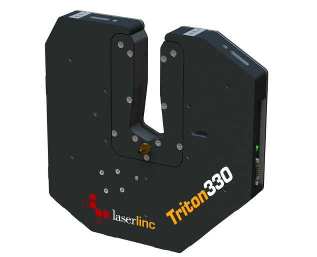
LaserLinc Triton laser micrometer with V-block fixture for troubleshooting and verification
A LaserLinc Triton micrometer in a controlled bench fixture. Good troubleshooting separates the product and fixture from the optical, electronic, communication, and software layers.
Before changing settings

Five checks that solve many laser micrometer problems

Record the symptom before touching anything, then move through the measurement chain one layer at a time. Do not change several settings together. A quick fix is only useful when you still know which action changed the result.

01Ask what changed

Recipe, product, PC image, network adapter, gauge, cable, guide, line speed, water, maintenance, or physical location.

02Check external power and data

Inspect connectors and approved power hardware. Confirm the controller or software is receiving changing data rather than one frozen value.

03Clear the optical path

Look for residue, haze, mist, spray, guides, hands, tooling, or another object crossing any laser axis.

04Stabilize the product

Confirm the product stays inside the usable field without whip, sag, guide contact, rotation surprises, or bubbles and droplets.

05Test a known reference

Use the approved verification standard and method. A reference separates product variation from a measurement-system problem.

Do not start by recalibrating. Calibration or adjustment can hide the evidence needed to identify contamination, motion, configuration, or product-state problems. First capture screenshots, values, changing communication status or data, error text, and the result from a known reference.
Troubleshoot the complete system

A laser micrometer reading travels through six different layers

The number on the screen is the end of a chain. A fault at any earlier layer can produce the same visible symptom. Work from the physical process toward the final decision rather than assuming the sensor is defective.

1Product and processActual diameter, ovality, temperature, speed, transparency, surface condition, vibration, and dimensional events.
2Presentation and environmentGuides, fixture, field position, sag, water, steam, dust, residue, static, and nearby machine motion.
3Optical measurementLaser axes, windows, edge recognition, usable range, axis coverage, measurement rate, and internal diagnostics.
4Power and communicationApproved power path, cables, connectors, network adapter, serial mapping, processor, and packet flow.
5Software and recipeTotal Vu or controller configuration, units, averaging, thresholds, axis logic, product profile, and saved settings.
6Decision and controlDisplay, alarm, PLC tag, marker, cutter, process-control output, report, or final quality disposition.

LaserLinc’s current architecture can combine Axion and Triton laser micrometers with Total Vu, SmartLinc, ultrasonics, defect inspection, and plant communications. That flexibility is useful, but it also means the fault can be upstream or downstream of the micrometer itself.[3][4]

Interactive symptom explorer

Start from what the system is doing now

Select the closest symptom. The result identifies the first evidence to collect, the safest initial checks, and when to move into the guided assistant or LaserLinc support.

No reading or intermittent reading

Separate loss of product detection from loss of communication. A blank value can be caused by blocked optics, product outside the usable field, the wrong transparent-product logic, interrupted power, a cable problem, or a software configuration that no longer points to the installed gauge.

  • Confirm external power, approved cables, and changing communication activity.
  • Check whether the gauge status view detects edges when a known opaque reference enters each axis.
  • Record whether the symptom affects every product, one recipe, one axis, or one PC.
Power or dataEdge detectionConfiguration
Detailed troubleshooting

10 common laser micrometer problems and what to check first

Each section keeps the diagnosis separate from the repair. The first checks are intentionally non-invasive. A result that points toward an internal gauge, power, control, or wiring fault should be escalated rather than improvised.

Screenshot note: The restored images show the Total Vu screens and hardware used in the original guide. Menu names, button locations, network values, and available settings can vary by software version, controller, model, and commissioned system. Use the screenshot to find the type of information, then verify the approved configuration for the installed system.
1. The gauge has no power or drops out intermittently
Typical symptomNo status, intermittent restart, frozen data, or communication that returns when a cable is moved.
Safe first checksInspect approved external power hardware, cable seating, strain relief, connector damage, and recent machine work.
Escalate whenThere is heat, odor, arcing, exposed conductors, repeated fuse or supply trips, or visible enclosure damage.

Industrial vibration, washdown, coolant, repeated flexing, and accidental pull loads can damage a cable without creating an obvious external break. Confirm whether the problem follows one cable, one port, one power source, or one gauge. Use only the approved power arrangements for the installed LaserLinc model. Some systems support more than one factory-approved power architecture, but an alternate-power test should be planned with the system documentation or support team rather than treated as a universal fix.

What this check does not prove: A powered gauge can still have a communication, configuration, optical, or application problem. Record whether status indicators remain stable while the measurement disappears.

Ethernet and Power over Ethernet connector on a LaserLinc laser micrometer
Inspect the external data and power connection. Reseat the approved Ethernet or PoE cable, inspect the latch and strain relief, and note whether moving the cable changes the symptom.
Twelve volt power connection on a LaserLinc Triton laser micrometer
Confirm the installed power architecture. Some LaserLinc models support a separate 12 V connection. Do not change from PoE to another supply unless that path is approved for the installed model and system.
2. Total Vu or the controller is not receiving gauge data
Typical symptomThe gauge is powered, but the software does not list it, changing communication status or data is frozen, or PLC tags stop changing.
Safe first checksConfirm the intended Ethernet adapter, cable, processor, network path, firewall policy, and gauge-status activity.
Escalate whenThe site cannot confirm the approved network settings or the problem began after IT, PC, switch, or software changes.

Do not publish or apply one fixed IP address as though every installation is identical. Direct-connected systems, plant networks, SmartLinc processors, replacement PCs, and legacy configurations can use different approved settings. Compare the current configuration with the system backup, commissioning record, or LaserLinc support guidance.

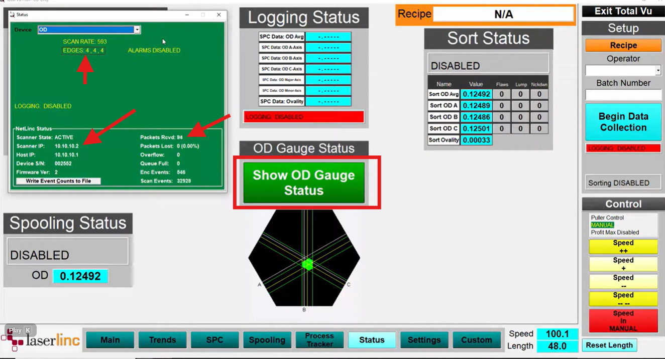
In a LaserLinc gauge-status view, changing changing communication status or data and edge information help separate communication from product detection. If packets are changing but edges are not, move toward optics, product presentation, and recipe logic. If packets are not changing, stay with the external data path before changing measurement settings.

LaserLinc Total Vu OD Gauge Status screen showing changing communication status or data, scan rate, edges, and product position
Where to look in Total Vu: in the pictured version, open System Settings and then Show OD Gauge Status. A changing Packets Received count confirms data is arriving. Edge counts and the product-position graphic help separate communication from product detection.
3. The installed gauge and software configuration no longer match
Typical symptomThe system stopped working after a gauge swap, PC replacement, restored image, software update, or configuration-file change.
Safe first checksRecord model and serial numbers, compare the active configuration with the physical system, and locate the last known-good backup.
Escalate whenProtected configuration, calibration data, device identity, or controller mapping must be changed.

A measurement application can contain device identity, axis assignment, range, edge logic, communication, units, averaging, recipes, and control outputs. A configuration that opens without an error can still point to the wrong device or use settings copied from another line. Confirm the physical gauge, processor, PC, software version, and active application as one system.

Good practice: Save a dated configuration backup after commissioning and after every controlled change. Record who changed the system, why, and what verification was completed before production resumed.

LaserLinc Total Vu scanner configuration screen showing the configured micrometer serial number
Where to compare the gauge identity: in the pictured Total Vu version, open Full Configuration, select the scanner configuration, and compare the configured serial number and model with the label on the physical micrometer. Menu paths can differ by version.
4. The laser is on, but the product is not detected correctly
Typical symptomNo value, too many detected edges, an impossible diameter, or detection that works on one material but not another.
Safe first checksUse a known opaque reference, inspect each axis, confirm usable field position, and load the correct product recipe.
Escalate whenThe application involves clear, translucent, reflective, multi-strand, figure-eight, or unusual geometry and the correct logic is uncertain.

Laser micrometers measure an outside silhouette, but transparent and complex products require the correct model and edge-recognition configuration. LaserLinc states that its current laser systems can measure clear materials, yet that capability still depends on the selected gauge, optical condition, product presentation, and recipe.[3]

Do not assume that enabling one transparent-product setting solves every clear-tube problem. First prove the gauge sees a stable reference, then introduce the actual product and review the detected edges by axis. Guides, droplets, a second strand, a braid feature, or a moving reflection can be interpreted as part of the product.

LaserLinc Total Vu gauge status screen highlighting product position in the micrometer field of view
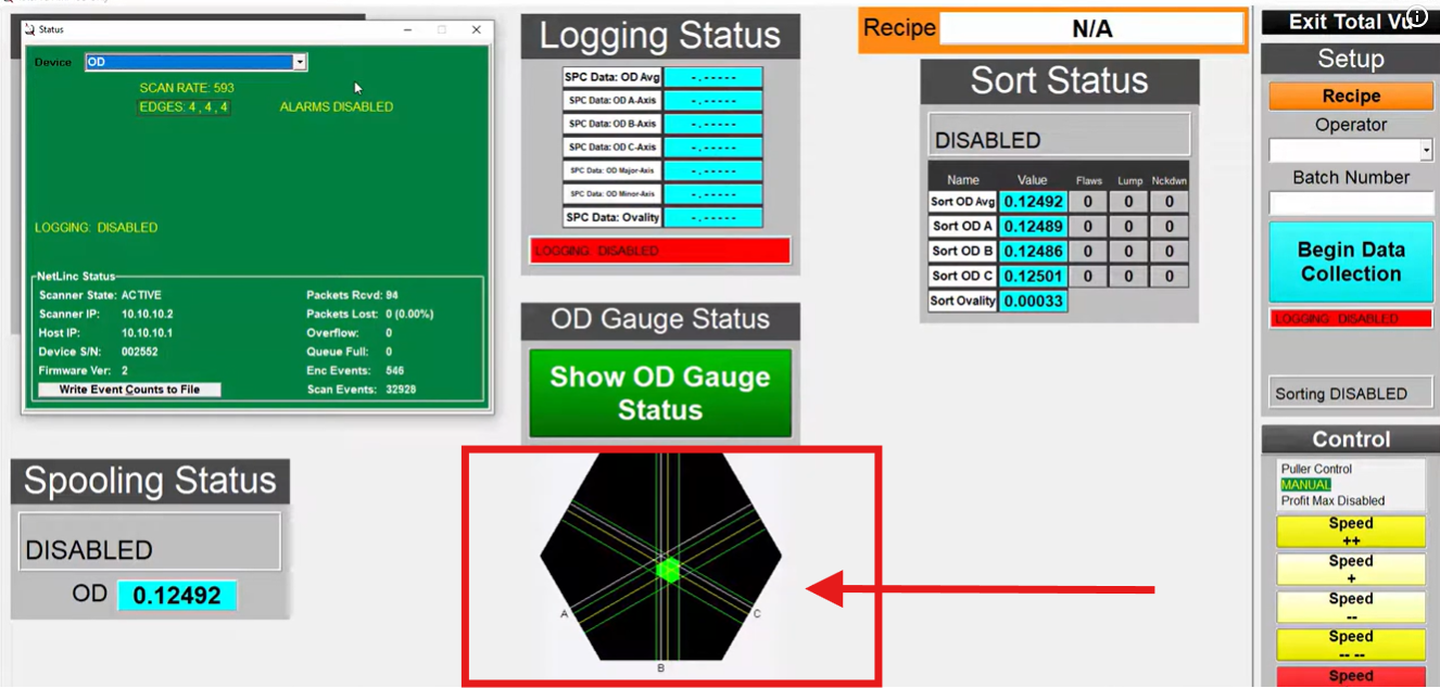
Check product position and detected edges. The gauge-status view shows where the product is located in the measurement field and whether each axis is returning usable edges.
LaserLinc Total Vu configuration screen with Glass Logic status visible in OD Gauge Settings
Check the active product logic. The pictured OD Gauge Settings area shows the Glass Logic status. Transparent-product logic is recipe and application dependent, so confirm the intended setting rather than turning it on universally.
5. Dirty windows, mist, water, or residue is disturbing the optical path
Typical symptomNoise grows during the shift, one axis degrades first, or the reading improves after the line stops.
Safe first checksInspect windows and the entire beam path under safe conditions. Compare dry and running environments.
Escalate whenContamination is inside the enclosure, a window is damaged, or cleaning materials and procedure are uncertain.

Polymer film, oil mist, dust, water droplets, steam, and overspray can scatter or block the beam. Use the cleaning method approved for the installed model and window material. A lint-free optical wipe may be appropriate, but do not assume that every solvent is safe for every coating, seal, or enclosure.

If contamination returns quickly, correct the environment rather than turning cleaning into the only maintenance plan. Options can include relocation, shielding, improved drainage, controlled air purge, cleaner compressed air, or changes to spray and exhaust. An air purge protects the optical path; it does not correct product whip or an unsuitable measurement location.

LaserLinc Triton laser micrometer equipped with an air purge connection
Environmental protection example: a clean, properly regulated air purge can help keep dust, mist, and residue out of the optical path. It does not replace approved window cleaning or correct an unsuitable measurement location.
6. The diameter reading jumps because the product is moving or poorly presented
Typical symptomNoise changes with speed, guide pressure, cooling water, tension, operator handling, or product position.
Safe first checksObserve the product path, compare stopped and moving readings, inspect guides, and review unsupported span and vibration.
Escalate whenThe line needs a new guide, stand, roller arrangement, fixture, or measurement location.

“Center the product” is useful advice, but it is incomplete. The product must remain inside the gauge’s usable field with enough margin for normal motion. It also must not rub, flatten, rotate unpredictably, or be forced into a shape that the process does not normally create. A small flexible tube can sag; wire can whip; a hot profile can twist; a V-block can lock an oval part into one orientation.

Review the measurement as a mechanical system. Compare each axis, line speed, tension, guide spacing, roll condition, water turbulence, and product temperature. The right correction may be a purpose-fit guide or fixture rather than more software averaging.

LaserLinc Total Vu product centering display for a triple-axis laser micrometer
Use the centering view as evidence. Watch whether the product marker moves with speed, water, tension, or guide changes. A centered average position can still hide rapid whip or rotation.
LaserLinc Triton laser micrometer with a V-block fixture supporting tubing
Control the physical presentation. A purpose-fit V-block, guide, or roller arrangement can make the product repeatable, but the support must not flatten, rub, or force the part into an unrepresentative shape.
7. Two or three axes disagree
Typical symptomOne axis reads high, ovality changes with rotation, or the average looks acceptable while individual axes do not.
Safe first checksMeasure a round reference, rotate the product, compare axis trends, and inspect axis-specific windows and obstruction.
Escalate whenA known round standard shows persistent a persistent error on one measurement axis or the product geometry requires more angular coverage.

Axis disagreement can be real. An oval, flat, twisted, figure-eight, or asymmetric product presents different projected widths to different laser directions. The disagreement can also come from contamination on one axis, a product crossing the field at an angle, a guide or fixture intersecting one beam, or an axis-specific configuration problem.

Use a round reference to separate the gauge from the product. Then rotate the actual product and observe whether the high axis follows the part or stays with the gauge. The single-, dual-, and triple-axis guide explains why more axes improve angular coverage but do not replace a full surface scanner or internal measurement.

LaserLinc Total Vu OD Gauge Status screen for comparing individual axes and detected edges
Compare axes before averaging them together. The status screen can show axis-specific edges, scan activity, and values. Test a round reference, then rotate the actual product to see whether the high reading follows the part or stays with one gauge axis.
8. Inline and offline measurements do not agree
Typical symptomThe inline gauge is repeatable, the bench method is repeatable, and the two still disagree by a consistent or changing amount.
Safe first checksMatch length location, product temperature, time after production, orientation, tension, fixture, contact force, and formula.
Escalate whenThe comparison method, uncertainty, or product-state relationship has not been formally defined.

A hot moving product in water is not the same measurand as a cooled, relaxed sample measured later in a laboratory. Polymer shrinkage, draw, tension, water film, sample cutting, ovality orientation, fixture force, and reference location can create a genuine difference. Neither result should be forced to match by an arbitrary offset until those conditions are controlled.

Build a correlation study by recipe. Mark the measured length position, condition the sample, use the approved bench fixture, retain individual-axis data, and compare across the full operating range. For medical tubing and finished parts, the fixturing guide explains why support and orientation are part of the method.

LaserLinc Total Vu screen comparing bare, hot, and cold inline measurements
Inline state matters. This Total Vu example keeps bare, hot, and cold measurements visible together so real process-state differences are not hidden by one forced offset.
LaserLinc Total Vu offline part measurement and batch statistics screen
Offline state matters too. A bench workflow can control rotation, force, part identification, and batch statistics. Correlation requires matching length position, temperature, timing, fixture, and formula between the two methods.
9. A verification pin or reference standard does not read correctly
Typical symptomOne or more standards show bias, repeatability has changed, or the result depends on position and orientation.
Safe first checksClean the standard and windows, confirm units and recipe, control presentation, repeat by axis, and review the standard certificate.
Escalate whenBias remains after controlled verification or adjustment would affect protected calibration data.

Verification asks whether the complete system produces acceptable results under a defined test. It is not automatically the same as calibration, and calibration is not automatically the same as adjustment. Use standards that cover the working range, not one convenient pin near the middle. Record temperature, fixture, position, axis results, repeat count, and acceptance criteria.

NIST defines metrological traceability as a property of a measurement result established through a documented calibration chain, with each calibration contributing uncertainty. It is not a permanent label attached to the micrometer.[7] Use the Calibration Pin Size Calculator to plan reference sizes, then confirm the facility’s approved metrology procedure.

LaserLinc Triton micrometer in a V-block fixture for controlled verification
Present the reference repeatably. Use the approved clean standard, fixture, position, and axis sequence. A pin resting at a different height or angle can change the test condition.
LaserLinc Total Vu screen showing the Calibrate Laser Micrometer control and scanner configuration
Verification comes before adjustment. The pictured Total Vu version shows the calibration control in OD Gauge Settings. Do not use it merely because a single check looks wrong. Preserve the evidence and follow the approved calibration procedure.
10. The gauge misses short lumps, neckdowns, or another critical event
Typical symptomA known defect passes through the line, but the display, alarm, marker, or report does not capture it consistently.
Safe first checksDefine defect length, line speed, per-axis observation rate, averaging, update rate, alarm logic, and angular position.
Escalate whenThe defect is too short, too localized, between axes, appearance-only, internal, or outside the installed gauge’s range and rate.

A high advertised measurement rate does not by itself guarantee detection. The relevant chain includes per-axis observation rate, internal filtering, output update, controller scan, alarm persistence, marker or cutter delay, and the physical length of the event at maximum line speed. Heavy averaging can make a trend look calm while suppressing the event the plant needs to catch.

A laser micrometer is strongest for outside dimensions and silhouette-changing events. A narrow scratch or pit may require FlawSense full-surface topography. An internal wall, lumen, or concentricity issue may require UltraGauge or a BenchLinc architecture. Use the calculator below as a first timing screen.

LaserLinc Total Vu gauge status screen showing scan rate and live edge counts
Start with the actual observation rate. The gauge-status view shows scan activity and edge detection. The shortest event must still survive averaging, software updates, PLC scans, and alarm persistence.
LaserLinc Total Vu trend screen for reviewing dimensional changes by length
Review the event in the trend and length domain. A calm average can hide a short lump or neckdown. Retain enough time or length resolution to prove the target event is visible before tuning the alarm or marker.
Interactive timing screen

Will the measurement chain observe a short event often enough?

Enter the event length, maximum line speed, and the effective per-axis observation rate that reaches the diagnostic or alarm logic. The result estimates event duration, longitudinal observation spacing, and observations across the event.

Use the effective rate after axis sharing, averaging, filtering, communications, and the logic that actually makes the decision.
Event duration0.42 ms
Observation spacing0.120 in
Estimated observations0.4
Screening resultLow coverage
The example event is shorter than the estimated distance between observations. A miss is possible even before angular coverage and downstream logic are considered.

Not a probability-of-detection model: This estimate does not account for beam width, defect slope, angular position, product motion, edge-recognition behavior, controller scan, alarm persistence, marker delay, or whether the event changes the measured silhouette. Validate with representative good, borderline, and reject product at the maximum operating speed.

Measurement confidence

Verification, calibration, and adjustment are different activities

Using the terms interchangeably can create unnecessary changes and weak records. The facility’s measurement-management system should define the purpose, interval, standards, acceptance limits, responsibilities, and response to an out-of-tolerance result.

VerificationDoes the system meet a defined requirement now?

Compare one or more known standards with an approved method and acceptance rule. Verification can be routine and does not necessarily change the instrument.

CalibrationWhat is the relationship between indication and reference?

A documented calibration establishes results and uncertainty over the defined conditions and range. It may reveal bias without changing the instrument.

AdjustmentShould the system be changed?

Adjustment alters the system to reduce error. It should be controlled, authorized, followed by verification, and never used to hide an unresolved environmental or method problem.

ISO 10012:2026 specifies requirements for a measurement management system intended to provide confidence in the validity and reliability of measurement results.[9] A practical laser micrometer program should include clean standards spanning the production range, controlled presentation, environmental limits, protected recipes, documented results, and a response plan for failed verification.

1Bracket the working range

Use several suitable standards rather than relying on one convenient nominal near the middle.

2Control presentation

Use the same fixture, field position, orientation, cleanliness, and sequence defined by the procedure.

3Retain individual axes

An average can hide an axis-specific bias, contamination issue, or presentation problem.

4Document the response

Define who investigates, whether product impact is assessed, and when service or adjustment is required.

When troubleshooting becomes application review

The gauge may be working correctly but solving the wrong measurement problem

Repeated service calls sometimes reveal an application mismatch rather than a failed instrument. LaserLinc is not only a micrometer manufacturer. Its current portfolio combines laser micrometry, ultrasonics, full-surface defect inspection, automated sample inspection, process visualization, and custom application configurations.[4]

Axis or range mismatchAxion or Triton review

One, two, and three axes serve different shapes, ranges, access conditions, and ovality risks. More axes are not automatically better for every line.

Internal geometryUltraGauge or BenchLinc

Outside laser axes do not directly measure wall distribution, lumen, ID, or concentricity. Add the measurement physics that the requirement actually needs.

Localized surface flawsFlawSense

A scratch, pit, crack, or narrow bump may not change one or more silhouettes enough for reliable detection. Full-surface topography is a separate architecture.

Long finished partsMetron and purpose-fit fixtures

Catheters, guidewires, tapers, and multi-zone parts need controlled handling, position, and recipes in addition to a sensor.

Data and control mismatchTotal Vu or SmartLinc architecture

The correct measurement can still fail the application if the plant needs different visualization, tags, reports, alarms, marker logic, or process control.

Changed applicationSample and factory review

New material, speed, size, transparency, shape, defect, or environment may require a new configuration, accessory, location, or system rather than another repair.

Escalation and recovery

Use LaserLinc and Gauge Advisor support before replacing a working system

When the external evidence points beyond routine checks, capture the system information before calling. A model, serial number, software version, configuration backup, screenshots, error text, recent changes, and representative product can shorten the path to a useful answer.

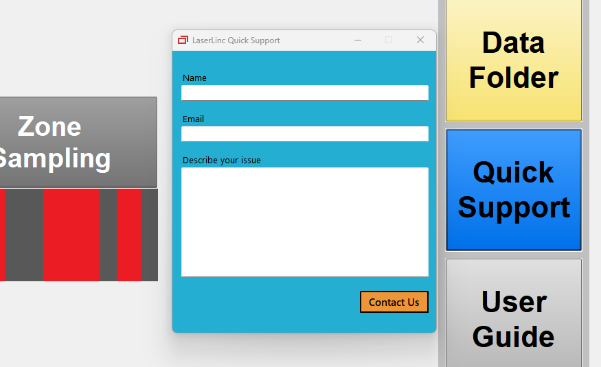
Remote supportLaserLinc Quick Support

LaserLinc’s Quick Support application lets an authorized staff member view and operate the host PC with the customer’s permission for configuration, diagnostics, and training. Internet access and the site’s security approval are required.[5]

Service and warrantyRMA and typical four-year coverage

LaserLinc publishes a typical four-year warranty for scanning laser micrometers and accessories, with parts and labor coverage and no-charge phone, email, and interactive support for the original purchaser under the stated terms. The actual contract governs.[5]

Local application supportGauge Advisor coordination

I help define the symptom, collect the right evidence, coordinate LaserLinc support or RMA activity, review whether the application has changed, and prepare replacement, upgrade, accessory, or new-system options when needed.

LaserLinc laser micrometer with air purge for dusty or mist-prone measurement environments
An approved air-purge or environmental accessory can protect the optical path when contamination is the real problem. It does not replace correct product guiding or application sizing.
LaserLinc Quick Support application for remote technical assistance
Quick Support gives the customer-controlled remote path used by LaserLinc for software, configuration, and system diagnostics.

LaserLinc’s current support hours are Monday through Friday, 8:00 a.m. to 5:00 p.m. U.S. Eastern Time, with phone, email, Quick Support, and RMA paths published through its resource center.[6]

Have this ready

Laser micrometer troubleshooting and support checklist

Good evidence is more useful than a long description that the reading is “bad.” Copy this list into the support request or maintenance ticket.

  • System identityGauge model and serial, controller or processor, PC, Total Vu or other software version, and line name.
  • Exact symptomNo reading, intermittent, noisy, biased, axis disagreement, verification failure, communication loss, or missed event.
  • When it beganDate, shift, product, startup state, and the last time the system was known to work correctly.
  • Recent changesProduct, recipe, PC image, network, cable, gauge, software, guide, line speed, maintenance, or relocation.
  • Gauge-status evidencePower state, packets or communication activity, detected edges, axis values, alarms, and screenshots.
  • Product and processMaterial, color or transparency, OD range, shape, temperature, normal and maximum line speed, tension, and water or mist.
  • Physical presentationGuide type, unsupported span, product motion, field position, fixture, rotation, and anything crossing a beam.
  • Reference resultStandard ID, certified size, measured values by axis, repeat count, temperature, position, and procedure.
  • Configuration filesCurrent application, last known-good backup, recipes, device identity, and any exported logs or reports.
  • Safety and urgencyAny heat, odor, arcing, damaged hardware, production stoppage, spare availability, and requested service timing.
Continue the measurement review

Related Gauge Advisor tools and guides

Frequently asked questions

Laser micrometer troubleshooting FAQs

What should I check first when a laser micrometer has no reading?

Separate power and communication from product detection. Confirm approved external power, cable seating, changing packet or status activity, a clear optical path, a known opaque reference in each axis, and the correct active configuration before changing calibration.

Should I reboot the software or PC?

A controlled restart can be a useful diagnostic, especially after a network or software state problem, but capture the error and status first. If rebooting repeatedly restores operation, the underlying communication, driver, power, or configuration issue still needs to be identified.

Can dirty windows make the diameter read too large or too small?

Contamination can reduce signal quality, introduce false edges, create intermittent detection, or destabilize one axis. The direction of the error is application-dependent, so do not apply a generic correction. Clean and verify using the approved procedure and a known standard.

Why do two laser axes report different diameters?

The product may actually be oval or orientation-sensitive. The difference can also come from one dirty axis, product tilt, a guide in the beam, or an axis-specific configuration issue. Use a round reference and rotate the product to separate the product from the gauge.

Can a laser micrometer measure clear tubing?

LaserLinc publishes capability for clear materials, but the correct gauge, optical condition, edge-recognition configuration, recipe, product presentation, and sample validation still matter. Do not assume one setting works for every transparent polymer and wall construction.

How often should a laser micrometer be calibrated?

There is no universal interval. The measurement-management system should use risk, use frequency, environment, history, customer requirements, verification results, maintenance, and consequence of error to establish the interval and intermediate checks.

Why does the laser micrometer disagree with a contact gauge?

The two methods can measure different product states and use different force, fixture, orientation, temperature, length location, and formulas. Define the measurand and run a controlled correlation instead of forcing one result to match the other.

Why does the system miss a short lump or neckdown?

The event may be shorter than the observation spacing, located between axes, filtered by averaging, or lost in controller and alarm timing. It also may be a local surface flaw that does not change the measured silhouettes enough for detection.

When should the gauge be returned for service?

Request support or an RMA when external checks, a controlled reference, configuration review, and approved cleaning do not resolve the issue, or when there is physical damage, persistent a persistent error on one measurement axis, internal contamination, power faults, or evidence that protected service is required.

What information should I send Gauge Advisor?

Send model and serial numbers, controller and software details, exact symptom, when it began, recent changes, screenshots, gauge-status evidence, product and line conditions, known-reference results, configuration backup, and representative samples when the application itself may have changed.

Technical basis

References and source notes

The references remain collapsible to keep the troubleshooting guide readable. They open automatically when printing.

Open technical references and source notes12 sources

Gauge Advisor is the authorized LaserLinc sales and applications support partner. LaserLinc sources are used for current equipment architecture, support, warranty, and service information. NIST, ISO, and OSHA sources provide independent measurement-management, traceability, uncertainty, and hazardous-energy context. No competing measurement-equipment manufacturer is cited.

  1. Gauge Advisor, legacy Laser Micrometer Troubleshooting Guide. Original article reviewed and corrected for 2026, including cable, communication, optics, product position, environmental, software, and detection topics.
  2. Gauge Advisor, Laser Micrometer Troubleshooting Assistant. Guided, non-invasive diagnostic covering no reading, instability, correlation, verification, communication, and application mismatch.
  3. LaserLinc, Laser Micrometers. Current Axion and Triton measurement scope, transparent-material capability, multi-strand context, SmartLinc integration, and typical four-year warranty.
  4. LaserLinc, Process Visualization. Total Vu integration of laser micrometers, UltraGauge, FlawSense, visualization, analytics, documentation, communications, and control tools.
  5. LaserLinc, Warranty and Service. Typical warranty periods, support terms, Quick Support capabilities, service limitations, and RMA guidance. The actual contract governs.
  6. LaserLinc, Resource Center. Current support contact, business hours, technical-support, and RMA paths.
  7. NIST, Metrological Traceability. Definition of traceability as a property of a result supported by a documented calibration chain and contributing uncertainties.
  8. NIST, Uncertainty and Dimensional Calibrations. Dimensional-metrology context for uncertainty, measurement conditions, artifacts, alignment, and interpretation of measurement results.
  9. ISO 10012:2026, Quality management, Requirements for measurement management systems. Current measurement-management requirements intended to support confidence in valid and reliable results.
  10. U.S. OSHA, Control of Hazardous Energy. Lockout and tagout context for servicing and maintenance where unexpected energization or release of stored energy can cause injury.
  11. LaserLinc, Axion Laser Micrometers. One- and two-axis, large-range, non-round, split-head, hot-product, and multi-strand application context.
  12. LaserLinc, Triton Laser Micrometers. Three-axis round and elliptical measurement, ovality, guide, and application context.

Send the evidence before replacing the gauge

Gauge Advisor is the authorized LaserLinc sales and applications support partner. I help manufacturers evaluate, select, quote, integrate, and support LaserLinc Axion and Triton micrometers, SmartLinc, Total Vu, UltraGauge, FlawSense, BenchLinc, Metron, fixtures, guides, and related measurement systems.

Gauge Advisor supports equipment selection and integration for the manufacturers represented here; independent process consulting is not offered. Send the completed checklist, system screenshots, configuration details, known-reference results, line conditions, and representative product when available. I will respond within one business day, often within a few hours.

  • Symptom and evidence review
  • LaserLinc support and RMA coordination
  • Configuration, fixture, and application screening
  • Replacement and upgrade options
  • Sample testing and factory application engineering
  • Quotations, integration, and ongoing support
Matthew Baker, founder of Gauge Advisor
Founder, Gauge Advisor LLC

Facebook
Twitter
LinkedIn

Need Help Selecting the Right Equipment?

Request Application Guidance

We won’t spam you with emails or call you a thousand times.

Tell us about your process, material, or measurement requirements.

A Gauge Advisor applications specialist will respond within 24 hours to discuss your measurement challenge and help determine the right solution for your line.

No obligation. Just start the conversation.