Updated August 21, 2026
An ultrasonic wall-thickness system can have the right transducers, processor, and software and still produce weak or unstable data if the sound path is not aligned with the moving tube. LaserLinc AutoPilot automates the positioning of the UltraGauge transducer assembly so operators can establish a usable ultrasonic signal faster during startup and product changeover. LaserLinc reports that initial production testing achieved proper alignment in under a minute, but the actual result remains application-dependent.[1]
If ultrasonic feasibility is not yet established, start with the UltraGauge Transducer Selector to screen the material, OD, wall range, and preliminary frequency path before evaluating positioning automation.
Connected process path: AutoPilot improves repeatable transducer positioning during startup, while transducer selection, water-path quality, material settings, and process stability still determine the wall result.
Related next steps: medical-tubing wall-thickness measurement, UltraGauge transducer selector, medical-tubing measurement selector, and medical-device measurement and inspection.
Why ultrasonic transducer alignment matters in tube extrusion
UltraGauge uses pulse-echo ultrasonics. Sound travels from each transducer through the water path and into the tube wall. Reflections from material interfaces are timed and interpreted to determine wall thickness. Water provides the acoustic coupling path, while transducer frequency, beam geometry, material response, and interface separation determine whether the echoes can be resolved.[3][6][7]
The illustration is directional, not a scale drawing of one UltraGauge model. A real system uses application-specific transducer frequency, orientation, working geometry, and signal settings. AutoPilot changes the assembly position relative to the product; it does not change the acoustic properties of the tube.
Water must carry sound from the transducer to the tube without excessive bubbles, contamination, or an unstable water level.
The product must remain inside the useful ultrasonic field so the intended wall interfaces produce stable, resolvable echoes.
Wall thickness is based on echo timing and the configured acoustic velocity. Alignment supports the signal but does not define velocity.
Multiple measurement points show how wall varies around the tube. A weak or missing channel can distort the apparent cross-section.
Not every unstable ultrasonic reading is an alignment problem
Select the closest condition. The diagnostic panel separates likely causes, the first checks I would make, and the role AutoPilot can reasonably play.
No usable wall signal at startup
Mispositioning may be part of the problem, but a complete loss of signal can also come from the water path, transducer selection, acoustic attenuation, gating, product geometry, or a hardware issue.
Confirm water level and flow, purge bubbles, clean the transducer faces, verify cables and channels, and review whether the selected frequency covers the material and wall range.
If every channel is weak, suspect a common acoustic or setup condition. If one channel is weak, inspect that transducer path and the local product position.
Automatic positioning can remove repeated manual searching for the best assembly location after ultrasonic feasibility and basic signal health are established.
How automatic ultrasonic positioning changes the startup workflow
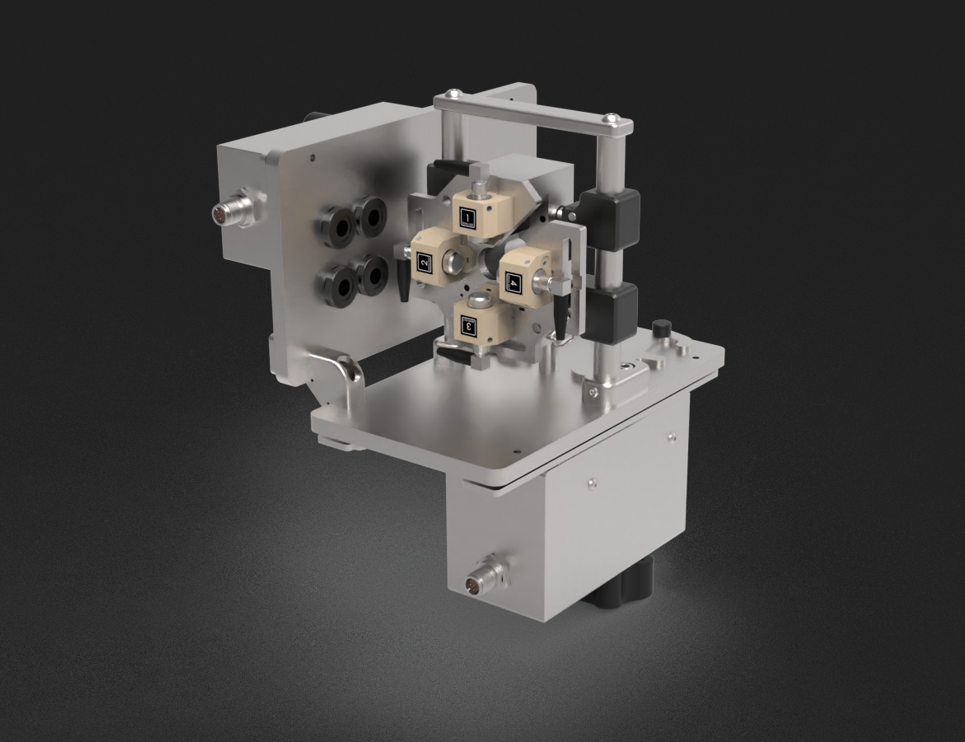
LaserLinc developed AutoPilot as an accessory for UltraGauge systems. Public launch information describes motorized positioning, adjustable roller guides, automatic alignment to the product, and manual override controls. The objective is to reach a strong, consistent ultrasonic signal without repeated knob adjustments or size-specific fixed inserts.[1]
The product enters the UltraGauge measurement area with the required water level, flow, bubble purge, and product support.
The operator starts the AutoPilot routine instead of manually searching for the preferred assembly position.
Motorized positioning changes the assembly relationship to the tube while adjustable roller guides support the product.
UltraGauge presents wall and concentricity information as the signal becomes usable. The recipe and signal setup still govern interpretation.
The operator can review the result, use manual override when needed, and proceed with the validated production workflow.

Reduces the repeated manual adjustment used to find a usable signal during startup and product changeover.
Supports a range of products without relying on a perfectly sized fixed guide block for every diameter.
Preserves operator flexibility for setup, maintenance, troubleshooting, and unusual application conditions.
AutoPilot is part of the LaserLinc ultrasonic architecture. Retrofit compatibility depends on the existing model, tank, controls, space, and quoted configuration.
The benefit becomes easier to justify when the line starts often, runs many recipes, or depends on several operators and shifts.
LaserLinc reports proper alignment in under a minute during initial production testing. Treat this as a published example, not a guaranteed cycle time.
Manual adjustment, fixed guidance, or AutoPilot?
No one approach is automatically correct for every extrusion line. The right choice depends on product range, changeover frequency, surface sensitivity, operator workload, current startup performance, and whether UltraGauge feasibility is already proven.
| Positioning approach | Primary strength | Changeover burden | Product interaction | Best-fit boundary |
|---|---|---|---|---|
Manual roller-guided UltraGauge Flexible baseline | Straightforward, adjustable, and lower in automation content. Experienced operators can tune the position directly. | Requires operator time and judgment. The burden increases as recipe count, shifts, and startup frequency increase. | Rollers support the tube with lower sliding friction than a tight fixed insert when properly selected and adjusted. | Reasonable for stable products, few changeovers, short manual setup, and a trained team with a controlled method. |
Size-specific fixed guidance Direct restraint | Can constrain product position directly when the insert is correctly sized and the product tolerates the contact. | May require the correct guide size, replacement parts, cleaning, and physical reconfiguration between products. | LaserLinc notes that poorly matched guide blocks can create friction, pulsation, abrasion, or occasional breakage.[1] | Evaluate carefully for soft, tacky, delicate, very small, or high-speed products where friction and surface contact matter. |
UltraGauge with AutoPilot Automated positioning | Standardizes the search for the measurement position and reduces operator-dependent alignment work. | Best case is a button-initiated routine followed by live data review. Actual time and operator steps depend on the complete application. | Uses adjustable roller guides and avoids fixed guide inserts in the published AutoPilot architecture. | Strongest for proven ultrasonic applications with frequent starts, multiple recipes, meaningful manual delay, or shift-to-shift setup variation. |
Is AutoPilot a strong fit for this extrusion line?
This tool identifies the most sensible next step. It does not replace an UltraGauge transducer review, representative sample testing, tank and mechanical review, or the final LaserLinc configuration.
What AutoPilot will not fix
Automatic positioning is valuable because it removes one source of setup delay and variability. It should not become a reason to skip the rest of the ultrasonic and extrusion diagnosis.
Very thin walls, thick walls, metals, filled polymers, foams, and attenuating materials can require different frequency and transducer arrangements. Positioning cannot create echoes the application cannot resolve.
Air interrupts acoustic coupling. Water level, flow, filtration, temperature, bubble purge, and transducer cleanliness remain part of the measurement system.
A stable signal can still be biased if velocity, temperature relationship, gates, reference method, or layer model is wrong.
Multilayer, multilumen, braided, reinforced, and unusual internal geometries should be evaluated with representative samples and the intended transducer configuration.
Tube wander, vibration, buoyancy, sag, puller instability, and poor mechanical guiding may need line corrections before or alongside sensor automation.
If die centering, melt distribution, cooling, vacuum, or puller behavior is creating nonuniform wall, AutoPilot helps reveal the condition. It does not manufacture the correction.
Use the UltraGauge Transducer Selector to screen material, OD, wall range, and frequency, then confirm the actual construction, tank, and production state with LaserLinc. The selector itself notes that coupling, centering, bubbles, material response, and sample behavior can change practical performance.
AutoPilot is one layer of the complete tubing measurement stack
The strongest installation separates positioning, direct ultrasonic measurement, direct outside measurement, and calculated or interpreted results. That makes validation easier and prevents the report from implying that one device measures every characteristic directly.
Moves the compatible ultrasonic assembly relative to the product and supports the tube with adjustable roller guides. AutoPilot does not itself measure wall, OD, or ID.
Measures echo timing at multiple positions around the product to determine wall thickness and characterize wall distribution.
An optional laser micrometer measures the outside silhouette without contact and adds angular outside-diameter coverage.
Combines sensor data for visualization, statistics, alarms, reporting, and calculated geometry such as ID where the model and inputs are appropriate.

LaserLinc describes Total Vu as the common HMI layer that can bring together UltraGauge, Triton and Axion laser micrometers, FlawSense, analytics, documentation, and process integration.[5] For medical tubing, a complete architecture may use AutoPilot and UltraGauge near the cooling section, a Triton micrometer for OD and ovality, and Total Vu for live cross-section display, SPC, reporting, and qualified control.
Estimate the time and material exposure tied to manual alignment
This calculator uses your own startup frequency, alignment time, production rate, material cost, and risk assumption. It does not assume that every minute of startup output becomes scrap or that every AutoPilot installation reaches the same cycle time.
Excluded: AutoPilot and UltraGauge project cost, installation, qualification, maintenance, downtime not caused by alignment, process scrap after alignment, faster process control, avoided quality escapes, production contribution, financing, and overlapping operator tasks. Use the Medical Tubing Measurement ROI Calculator for a broader equipment justification and avoid counting the same startup loss twice.
Information needed before AutoPilot selection and qualification
AutoPilot should be reviewed as part of the complete UltraGauge measurement method. The application data below helps LaserLinc determine transducers, assembly size, tank integration, controls, positioning approach, and whether samples are needed.
- Product envelopeMinimum, nominal, and maximum OD; wall range; lumen geometry; ovality; straightness; and expected product movement.
- Material and constructionPolymer or metal grade, layers, reinforcement, braid, filler, foam, color, temperature, acoustic history, and any process changes.
- Current ultrasonic setupUltraGauge model, transducer frequency and style, processor, tank, roller guides, Total Vu version, and current recipe structure.
- Signal evidenceGood and poor waveforms, channel dropouts, current gain and gates, bubble behavior, screenshots, and any known correlation offsets.
- Startup baselineManual alignment time, number of adjustments, startups per shift or week, startup scrap, and how results vary by operator.
- Line mechanicsLine speed, water level, bubble purge, tank opening, available space, product height, buoyancy, vibration, guides, puller, and straight-line path.
- Measurement objectiveWall sections, minimum wall, concentricity, calculated ID, OD, ovality, closed-loop control, reports, alarms, and quality-system records.
- Representative samplesSmallest, largest, thinnest-wall, most flexible, most difficult construction, known good, borderline, and known problem product.
- Retrofit informationPhotos, tank and mounting drawings, clearances, existing part numbers, power and I/O, control cabinet, and desired installation timing.
- Validation methodOffline reference, sectioning or optical method, sample conditioning, measurement location, calibration chain, acceptance formulas, and MSA expectations.
Common mistakes when evaluating automatic transducer alignment
Assuming alignment is the same as measurement accuracy
Alignment affects signal quality and the consistency of the measurement geometry. Accuracy also depends on material velocity, temperature, transducer frequency, gates, calibration, reference quality, product state, and the accepted calculation. A perfectly positioned but incorrectly calibrated system can still be biased.
Quoting “under a minute” as a guaranteed production cycle
LaserLinc reports under-one-minute proper alignment in initial production testing. Actual cycle time depends on product, tank, water, signal, recipe, operator sequence, line motion, and final configuration. Use a trial or conservative planning value in the plant business case.
Selecting AutoPilot before proving ultrasonic feasibility
Automation cannot resolve an application that lacks separable echoes. Confirm material, wall range, interfaces, frequency, acoustic attenuation, water path, temperature, and signal quality first, especially for very thin, multilayer, multilumen, braided, filled, or metallic products.
Ignoring bubbles, water flow, and transducer cleanliness
Air bubbles, low water level, dirty windows, inconsistent flow, and a contaminated tank can create intermittent signal loss that looks like product movement. The current UltraGauge datasheet recommends a water source for air-bubble purge and defines tank requirements by model.[3]
Expecting AutoPilot to center the die or correct wall eccentricity
AutoPilot positions the measurement assembly. Die adjustment remains a process action guided by the measured wall and concentricity result. If the product is genuinely nonconcentric, the system should display the problem rather than hide it.
Using sensor motion to mask severe product wander
Persistent vibration, sag, floating or sinking behavior, puller instability, and poor guide placement can reduce measurement capability and affect the product itself. Correct the line mechanics or define a validated guidance plan instead of relying on sensor movement alone.
Assuming every existing UltraGauge is a drop-in retrofit
AutoPilot is an UltraGauge accessory, but retrofit scope depends on the existing assembly, model, tank, available envelope, processor, software, controls, power, mounting, and revision level. Provide part numbers, photos, and drawings for review.
Calling calculated ID a direct ultrasonic measurement
UltraGauge directly measures wall interfaces. When synchronized OD is available and the geometry model is appropriate, Total Vu can calculate ID. Reports should preserve the distinction between direct wall measurements, direct laser OD, and calculated internal geometry.
Related Gauge Advisor resources
LaserLinc AutoPilot and ultrasonic alignment FAQs
What exactly does AutoPilot automate?
AutoPilot automates the positioning of a compatible UltraGauge transducer assembly relative to the extruded product. It replaces repeated manual positioning work during startup or changeover. UltraGauge remains the device that performs ultrasonic wall measurement.
Does AutoPilot always align the system in under a minute?
No universal cycle time should be promised. LaserLinc states that initial production testing consistently achieved proper alignment in under a minute. Product size, construction, water path, line motion, tank, signal settings, and configuration can change the actual result.
Does AutoPilot eliminate every guide or roller?
No. LaserLinc describes AutoPilot as using adjustable roller guides while eliminating the need for size-specific fixed guide blocks in the positioning approach. The rollers, product path, load, material, and surface sensitivity still need application review.
Can AutoPilot be added to an existing UltraGauge?
Possibly. AutoPilot is designed as an UltraGauge accessory, but compatibility should be confirmed from the current UltraGauge model, assembly part number, tank, mounting space, processor, software, power, controls, and mechanical condition.
Does AutoPilot continuously follow the tube during production?
Current public LaserLinc launch material emphasizes automatic positioning during startup and product changeover. The exact operating modes and any continuous or adaptive function should be confirmed for the quoted system rather than assumed.
Will AutoPilot improve measurement accuracy?
It can reduce operator-dependent positioning variation and help establish stronger, more consistent ultrasonic signals. It does not replace calibration, material-velocity setup, gating, reference correlation, uncertainty review, or MSA. It is better described as improving the repeatability and speed of the positioning condition.
Can it be used on soft, clear, multilumen, or multilayer tubing?
Clear material is not automatically a problem for ultrasonics because the method does not depend on optical transparency. Softness, deformation, acoustic attenuation, layers, lumens, interfaces, wall range, and product guidance can be important. Representative samples are appropriate for complex constructions.
Is a laser micrometer required with AutoPilot?
No. AutoPilot and UltraGauge can be used for ultrasonic wall and concentricity measurement. Add a Triton laser micrometer when the application also requires direct OD and ovality plus calculated ID or a fuller cross-section display.
What should I send for an AutoPilot application review?
Send the product OD and wall ranges, material and construction, current UltraGauge model and transducers, tank photos or drawings, line speed, water setup, current alignment time, number of changeovers, screenshots or waveforms, measurement objectives, and representative samples when available.
References and source notes
The references remain collapsible so this focused commercial article is easy to scan. They open automatically when printing.
Open technical references and source notes8 sources
Gauge Advisor is the authorized LaserLinc sales and applications support partner. LaserLinc sources are used for current AutoPilot, UltraGauge, and Total Vu architecture and manufacturer-published performance examples. ASTM, NDE-Ed, and NIST provide neutral ultrasonic and metrology context. No competitive equipment manufacturer is cited.
- LaserLinc, Improving Ultrasonic Wall Thickness Measurement with Automated Transducer Positioning, 2026. Official AutoPilot launch information covering the manual-alignment problem, motorized positioning, adjustable roller guides, removal of fixed guide blocks, manual override, and under-one-minute initial production testing.
- LaserLinc, Ultrasonic Measurement. Current UltraGauge product page describing wall thickness, concentricity, optional Triton OD integration, AutoPilot positioning, and frequent-changeover use.
- LaserLinc, UltraGauge Datasheet, 2026. Current published model, transducer-frequency, tank, adjustment, water, bubble-purge, roller-guide, processor, and ultrasonic operating information. Published ranges are application-dependent.
- LaserLinc, UltraGauge Application and Solution Brief. Manufacturer overview of medical tubing, wire and cable, multilayer, wall, concentricity, AutoPilot, laser measurement, and Total Vu use.
- LaserLinc, Total Vu Process Visualization. Current description of the common HMI and data architecture for UltraGauge, Triton and Axion micrometers, FlawSense, visualization, analytics, documentation, and integration.
- ASTM E797/E797M-21. General pulse-echo ultrasonic thickness-measurement context. This contact-method practice is not itself a validation standard for a specific inline immersion tubing system.
- American Society for Nondestructive Testing, Ultrasonic Testing. Industry-association overview of ultrasonic testing using high-frequency sound and returned echoes to obtain information about a test object.
- NIST, Metrological Traceability. Definition and practical guidance for relating measurement results to references through a documented calibration chain and associated uncertainty.
Review the ultrasonic application before automating the positioning step
Gauge Advisor is the authorized LaserLinc sales and applications support partner. I help medical tubing, catheter, wire and cable, and precision-extrusion manufacturers evaluate, select, quote, integrate, and support UltraGauge, AutoPilot, Triton and Axion laser micrometers, Total Vu, BenchLinc, Metron, and FlawSense.
Gauge Advisor supports equipment selection and integration for the manufacturers represented here; independent process consulting is not offered. Send the product dimensions, material and construction, current ultrasonic setup, tank photos, line speed, alignment baseline, signal screenshots, and representative samples when available. I will respond within one business day, often within a few hours.
- AutoPilot and UltraGauge fit review
- Existing-system retrofit screening
- Transducer, tank, and product-range review
- Sample testing and factory coordination
- Triton, Total Vu, data, and control integration
- Quotation and ongoing applications support