Medical tubing ultrasonic measurement

Medical Tubing Wall Thickness Measurement Systems

Compare inline LaserLinc UltraGauge systems—with optional AutoPilot positioning—and offline BenchLinc UT stations for direct wall-thickness measurement, concentricity, calculated ID, and documented process or QA workflows.

LaserLinc Authorized LaserLinc sales & support partner. Gauge Advisor helps medical tubing teams select, quote, integrate, and support ultrasonic, laser, software, and sample-inspection systems.
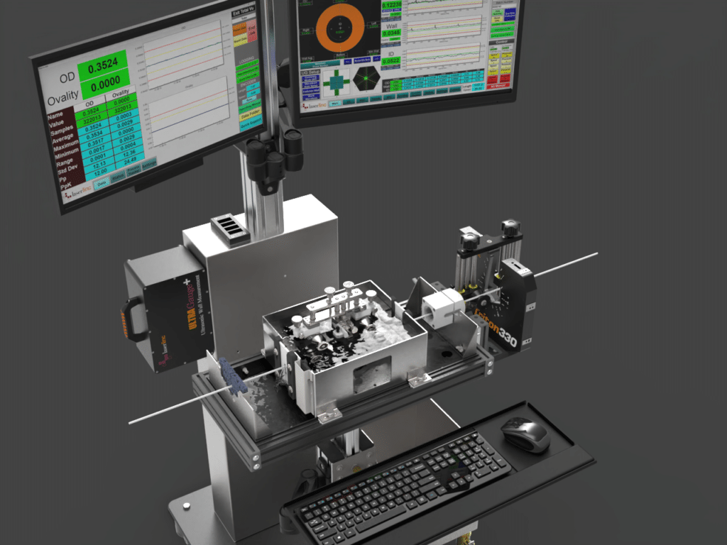
LaserLinc medical tubing extrusion system combining ultrasonic wall measurement, laser OD gauging, and Total Vu software
See the tube geometry an OD-only gauge cannot.
Direct ultrasonic wall
Wall distribution & concentricity
Calculated ID with laser OD
Direct wall data Pulse-echo ultrasonics calculates wall thickness from the time between echoes at material interfaces rather than inferring wall from OD
Inline & offline UltraGauge for extrusion and BenchLinc UT for controlled post-process inspection
Complete profile Add an optional laser micrometer and Total Vu for ovality, calculated ID, trends, SPC, and reports
Warranty & support Four-year warranty on LaserLinc-manufactured equipment plus free phone and remote support from LaserLinc engineers, staffed 8:00 a.m.–5:00 p.m. Eastern
Start with the inspection workflow

Where and how will the tube be measured?

Inline extrusion, rigid-tube QA, complete cross-section measurement, and short-sample inspection solve different problems. Choose the closest workflow before selecting the product name.

UltraGauge + optional AutoPilot

Measure wall thickness and concentricity while the tubing is being extruded

Continuous wall data shows operators what is happening between offline samples and gives the process immediate feedback during startup, die centering, and production.

  • Best whenYou need live wall distribution, concentricity, alarms, trends, or qualified closed-loop control.
  • MeasuresWall thickness directly and concentricity from the wall distribution; add laser OD for ovality and calculated ID.
  • AutomationAutoPilot automatically positions a compatible transducer assembly during startup or product changeover.

Fit note: material, wall range, layers, water coupling, transducer selection, line speed, product guidance, temperature, and the proposed gauge location are reviewed together.

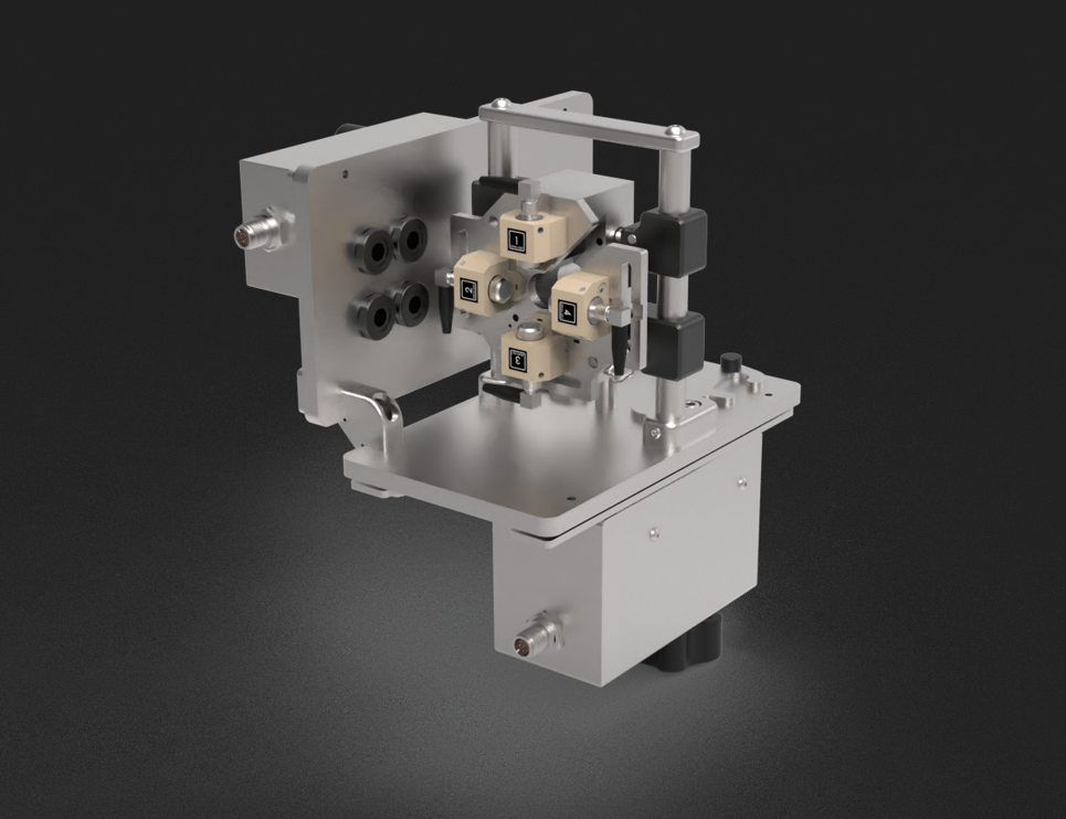
LaserLinc AutoPilot automatic positioning assembly for an UltraGauge ultrasonic medical tubing system
AutoPilot addresses transducer positioning. UltraGauge performs the ultrasonic wall measurement, and Total Vu displays and uses the result.
BenchLinc UT

Inspect wall and concentricity along rigid or cut-to-length tubing

BenchLinc UT brings ultrasonic measurement into a controlled offline station for rigid polymer tubing, hypotubes, cannulas, Nitinol, stainless tubing, and other suitable cut-to-length products.

  • Best whenYou inspect incoming tube stock, rigid parts, engineering samples, validation lots, or finished cut lengths.
  • MeasuresUltrasonic wall and concentricity along the accessible length; an optional laser micrometer adds OD, ovality, and calculated ID.
  • WorkflowEncoder-referenced results, part recipes, tolerance checks, statistics, stored data, and configurable reports.

Fit note: straightness, curvature, surface condition, usable sample length, acoustic response, and stable passage through the fixture must be confirmed with the real part.

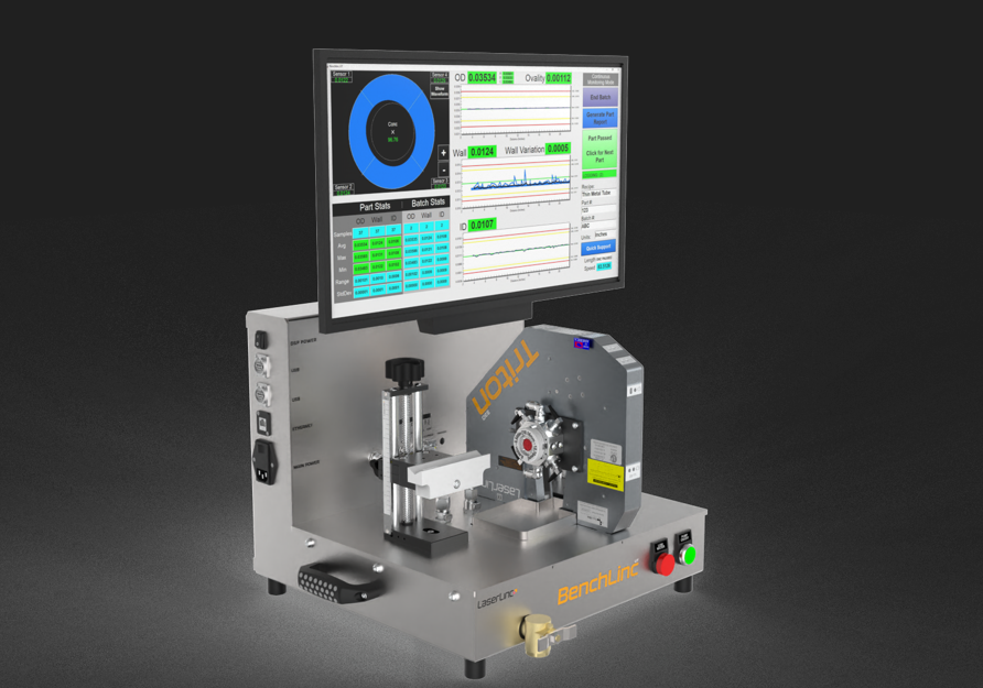
LaserLinc BenchLinc UT ultrasonic system for offline medical tubing wall thickness and concentricity inspection
BenchLinc UT combines the ultrasonic fixture, controlled sample path, Total Vu interface, and an optional laser micrometer for direct OD measurement in one station.
Ultrasonics + laser + Total Vu

Combine direct wall data with direct outside-diameter measurement

An ultrasonic system sees wall interfaces. A Triton laser micrometer sees the outside silhouette. Synchronizing the two gives operators a more complete dimensional picture without implying that one sensor directly measures every characteristic.

  • UltrasonicDirect wall-thickness paths and wall-distribution information used for concentricity.
  • LaserDirect OD and multi-axis ovality measurement without contacting the tube.
  • CombinedCalculated ID, cross-section visualization, recipes, SPC, alarms, reports, communications, and control workflows.

Measurement boundary: ID is calculated when valid, synchronized OD and wall data are available and the approved geometry model fits the product. The laser does not see through the wall.

Customizable LaserLinc Total Vu display showing medical tubing OD, wall thickness, concentricity, trends, and calculated ID
Total Vu can be tailored to show the cross-section, individual wall values, OD, calculated ID, trends, tolerances, statistics, and length-correlated data required by the process.
When ultrasonics is not the first choice

Use BenchLinc OD/ID for suitable short polymer samples

A short cut sample with an accessible lumen may be better served by a purpose-designed mandrel method than by an ultrasonic station. This is why the commercial decision should start with part handling—not a preferred technology.

  • Best whenShort polymer samples can be placed over the correct mandrel and rotated under controlled loading.
  • MeasuresLaser OD and ovality, wall relative to the mandrel datum, and calculated ID in a repeatable QA workflow.
  • BoundaryNot an inline or ultrasonic system and not the preferred path for long rigid or metallic wall profiles.

Fit note: sample length, lumen access, mandrel clearance, wall, flexibility, cut quality, friction, and controlled force determine whether the method is suitable.

LaserLinc BenchLinc OD ID system for controlled short-sample medical tubing inspection
BenchLinc OD/ID is the short-sample alternative when a controlled mandrel-based method fits the part and measurement plan.
Keep every output technically distinct

Separate direct measurement from calculated geometry

A complete tubing profile can combine several valid results. The report and validation plan should still show which sensor measured each input and which dimensions were calculated.

Wall thickness

UltraGauge or BenchLinc UT times the echoes from material interfaces to resolve configured wall paths.

Direct ultrasonic result

OD & ovality

An Axion or Triton laser micrometer measures the outside silhouette. Multiple axes add angular OD coverage.

Direct laser result

Concentricity

Wall readings around the tube characterize how evenly the internal passage is centered relative to the outside geometry.

Derived from ultrasonic wall distribution

Inside diameter

ID can be calculated when synchronized OD and wall data are valid and the accepted geometry model matches the part.

Calculated result
LaserLinc UltraGauge transducer arrangement measuring tubing wall around the circumference
01

Establish the acoustic path

Water couples high-frequency sound from each transducer into the tube. Bubbles, contamination, water level, temperature, and alignment can affect signal quality.

02

Resolve the interface echoes

The system uses echo timing and a configured acoustic velocity to calculate thickness. Frequency, gating, material, layers, and wall range are part of the method.

03

Compare wall around the tube

Multiple measurement paths show minimum, maximum, and distributed wall values used to evaluate concentricity or eccentricity.

04

Coordinate OD, data, and action

Total Vu can combine ultrasonic and laser data for cross-section visualization, tolerance logic, trends, SPC, reports, communications, and qualified process control.

Published starting range: LaserLinc currently describes ultrasonic wall capability from 0.001 in (25.4 μm) for suitable polymer products and from 0.003 in (76 μm) for suitable metals. These are application-screening points—not universal guarantees. Actual capability depends on material, layers, tube size, wall range, acoustic response, transducer configuration, presentation, and the required measurement uncertainty.

LaserLinc system architecture

Build the wall-measurement system around the process

Some projects need one ultrasonic station. Others add automatic positioning, laser OD, Total Vu, encoder feedback, offline verification, or line control.

LaserLinc UltraGauge ultrasonic wall thickness measurement assembly
InlineUltrasonicWall

UltraGauge

Continuous ultrasonic wall-thickness and concentricity measurement for suitable tube-extrusion applications.

Best for
Live process feedback, startup, trends, alarms, and wall control
Measures
Wall paths and wall distribution; calculated ID when paired with valid OD data
Review
Material, transducer range, water, line speed, guidance, and gauge location
Check UltraGauge feasibility
LaserLinc AutoPilot motorized transducer positioning system
AutomationSetupChangeover

AutoPilot

Automatic positioning for compatible UltraGauge assemblies to reduce repeated manual alignment work during startup and changeover.

Best for
Frequent starts, many recipes, several shifts, or meaningful manual setup time
Function
Positions the assembly; UltraGauge remains the measuring device
Review
Existing model, tank, space, controls, guides, product path, and retrofit scope
Review AutoPilot alignment
LaserLinc BenchLinc UT benchtop ultrasonic tubing inspection system
OfflineRigid tubingUltrasonic

BenchLinc UT

Controlled offline wall and concentricity inspection along suitable rigid, metallic, or cut-to-length tubing.

Best for
Hypotube, cannula, Nitinol, stainless, rigid polymer, incoming QA, and validation
Measures
Ultrasonic wall and concentricity; an optional laser micrometer adds OD, ovality, and calculated ID
Review
Acoustic response, straightness, surface, usable length, coupling, and handling
Explore offline ultrasonic inspection
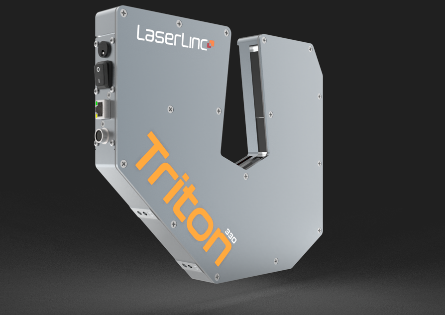
LaserLinc Triton 330 triple-axis laser micrometer for medical tubing OD and ovality
LaserODOvality

Triton laser micrometer

Noncontact outside-diameter and multi-axis ovality measurement that complements—not replaces—ultrasonic wall measurement.

Adds
Direct OD, axis-based ovality, outside-dimension trends, and calculated ID with wall data
Boundary
Does not directly measure through the wall or see the internal surface
Review
Axis count, range, product presentation, guides, mounting, speed, and data needs
Compare laser OD systems
LaserLinc Total Vu BenchLinc UT display for OD, wall thickness, concentricity, trends, and calculated ID
HMISPCReportsControl

Total Vu

A fully customizable visualization and workflow layer for live values, tube cross-sections, recipes, statistics, alarms, data, reports, communications, and process control.

Best for
Coordinated ultrasonic, laser, encoder, offline, and plant-data workflows
Supports
Configurable screens, SPC, reporting, saved data, OPC connectivity, and control logic
Customize
Not a black box: LaserLinc can tailor it to the process at no charge, or technically capable customers can configure it themselves
Discuss data and control requirements
Published model windows

UltraGauge ranges at a glance

Use these current published ranges only for preliminary screening. LaserLinc defines low frequency (LF) as 2.25–20 MHz and high frequency (HF) as 30–50 MHz. Material, acoustic impedance, transducer style and orientation, product state, and required uncertainty determine the actual application range.

Swipe horizontally to compare every model →

Approximate current LaserLinc datasheet ranges; LF and HF values are application dependent.
Model Wall points LF OD range HF OD range LF wall range HF wall range
UG412 4 0.01–0.45 in0.2–11.4 mm 0.01–0.30 in0.2–7.6 mm 0.003–0.20 in0.08–5.08 mm 0.001–0.05 in0.02–1.30 mm
UG430 4 0.02–1.15 in0.5–29.2 mm 0.02–0.75 in0.5–19.1 mm 0.003–0.50 in0.08–12.7 mm 0.001–0.05 in0.02–1.27 mm
UG460 4–8 0.25–2.30 in6.3–60 mm 0.25–2.30 in6.3–60 mm 0.003–1.0 in0.10–25.4 mm 0.001–0.05 in0.025–1.27 mm
Build the preliminary system path

Inline UltraGauge, BenchLinc UT, or another workflow?

Answer a few questions about the measurement, product, size, workflow, and data needs. The selector can recommend a coordinated system when more than one technology is required.

Loading the medical tubing measurement selector…

If the selector does not load, open it on its own page.

Application fit

Match the ultrasonic setup to the actual tube

Optical transparency alone does not determine ultrasonic feasibility. Acoustic transmission, wall range, layers, lumens, part state, product guidance, and the required uncertainty are more important.

Strong starting application

Single-lumen polymer extrusion

Inline UltraGauge can provide continuous wall and concentricity data during catheter, microbore, balloon, and precision tubing extrusion. Add laser OD for the fuller tube profile.

Review inline medical tube measurement →
Strong starting application

Raw Nitinol & metallic hypotube

Continuous-wall Nitinol, stainless, cannula, and similar tube stock can be a strong ultrasonic candidate inline or through BenchLinc UT before laser cutting, coating, or assembly.

Explore metallic tubing measurement →
Strong starting application

Rigid cut-to-length tubing

BenchLinc UT is the primary offline path when wall and concentricity must be inspected along a suitable rigid or semi-rigid tube rather than only at one cut face.

Review BenchLinc UT applications →
Confirm with samples

Multilayer & multilumen tubing

Multiple interfaces, thin layers, closely spaced lumens, braid, fillers, and unusual cross-sections can create overlapping or attenuated echoes. Representative samples establish which paths are reliable.

Start with the transducer screen →
Review the part state

Laser-cut, coated & assembled parts

Slots, struts, coatings, encapsulation, markers, joints, and attachments change both the sound path and sample handling. Measure the raw tube earlier when that better supports the control plan.

Compare raw and processed parts →
Choose the right alternate

Short soft polymer samples

When a short sample has an accessible lumen, BenchLinc OD/ID may provide a better controlled QA method. The selector separates this from inline UltraGauge and rigid-tube BenchLinc UT paths.

Compare the short-sample method →
Buyer comparison

Compare wall-thickness and supporting measurement paths

No one system is the universal answer. The strongest commercial recommendation matches the product state, direct measurement requirement, handling method, and speed at which the result must reach the process.

Swipe horizontally to compare every column →

Starting comparison; final configuration and capability require application review.
System Workflow Direct wall OD / ovality ID method Length data Best fit
UltraGauge Inline extrusion Yes—ultrasonic With added laser micrometer Calculated from valid OD + wall Yes, with stable motion and encoder data Continuous wall, concentricity, startup, trends, alarms, and control
BenchLinc UT Offline rigid or cut-to-length tube Yes—ultrasonic With optional laser micrometer Calculated with valid OD from the optional laser micrometer Yes, along the accessible sample length Hypotube, Nitinol, cannula, rigid polymer, incoming QA, and validation
BenchLinc OD/ID Offline short sample No—mandrel datum method Yes—laser + controlled rotation Calculated from OD and datum-based wall No—individual short samples Short polymer samples with accessible lumen and suitable mandrel fit
Laser micrometer Inline or bench OD No Yes—direct laser result Not without valid wall information Yes, with stable motion and encoder data OD, ovality, dimensional trend, and complementary outside geometry
Metron Automated offline OD profile No Yes—direct laser measurement No—OD and ovality only Yes—automated feed and optional rotation Automated OD and ovality profiles along long catheters, guidewires, tapers, zones, and transitions

Wall measurement does not prove surface integrity

OD, wall, concentricity, and calculated ID do not automatically detect a scratch, pit, crack, bump, exposed braid, or other anomaly unless it creates a detectable surface-height change. Add medical tubing surface-defect detection when that separate failure mode matters.

From a reading to a controlled workflow

Use Total Vu to visualize, document, and act on the result

The system value is not only the live wall number. A customizable interface, recipes, trends, tolerances, batch records, reports, communications, and validated control logic turn the measurement into a repeatable production or QA method.

Fully customizable, not a black box: LaserLinc can tailor Total Vu screens, calculations, recipes, reports, communications, alarms, and control logic to the customer’s process at no charge. Customers with the necessary technical skills can also configure the software themselves.

LaserLinc Total Vu medical tubing cross-section and process data display
Operator view

Live tube cross-section

Show individual wall paths, concentricity, OD, calculated ID, tolerance status, trends, and the dimensions that need attention.

Quality workflow

Recipes, SPC & reports

Standardize product setup, calculations, limits, statistics, batch collection, data retention, and configurable reporting.

Plant integration

Communications & data

Define the required PLC, SCADA, MES, historian, OPC, export, marker, cutter, or other interfaces during the application review.

Process action

Qualified feedback control

Wall, OD, puller speed, air, output, cooling, and transport delay interact. Closed-loop control must be configured and tuned for the actual extrusion process.

Responsive engineering support

Free phone and remote support before and after the purchase

LaserLinc provides free phone and remote support with engineers staffed from 8:00 a.m.–5:00 p.m. Eastern, so customers calling during support hours reach someone. Gauge Advisor remains involved through application review, integration, training, validation, and production support.

Thank you for coming onsite and for your assistance troubleshooting our issue. The LaserLinc micrometer works great!
Engineering team, Edwards Lifesciences — Irvine, California
01

Define the measurement and workflow

Share the material, construction, dimensions, tolerances, part state, line speed or sample length, current method, data needs, and whether the result must drive the process or verify it.

02

Confirm the ultrasonic and handling path

We review the transducer range, water path, product presentation, inline or offline system, optional laser micrometer, software, fixtures, controls, and representative samples.

03

Configure, quote, integrate, and support

Once the approach is confirmed, Gauge Advisor can coordinate the LaserLinc quotation, mechanical and controls review, installation planning, training, validation support, and ongoing application questions, then connect customers with LaserLinc’s free phone and remote engineering support.

Faster application review

What should you send for selection and pricing?

A drawing plus the information below is usually enough to establish the starting architecture, identify any sample-testing step, and prepare the right technical questions.

  • Polymer or alloy and full construction
  • Minimum, nominal, and maximum OD
  • Wall range and minimum-wall requirement
  • Target ID and accepted calculation method
  • Concentricity or eccentricity definition
  • Layers, lumens, braid, coatings, or fillers
  • Inline, offline, incoming, QA, or R&D use
  • Line speed, sample length, and part condition
  • Current reference and validation method
  • Reports, SPC, PLC, MES, alarms, or control
  • Tank, space, water, and installation details
  • Representative good and difficult samples
Common application questions

Medical tubing wall measurement FAQ

These answers establish the starting path. Final capability, configuration, and measurement uncertainty depend on the actual product, process, and intended workflow.

How is medical tubing wall thickness measured ultrasonically?
A transducer sends a high-frequency pulse through a water coupling path and into the tube wall. The system resolves reflections from material interfaces and uses their timing plus a configured acoustic velocity to calculate thickness. Frequency, gating, material, wall range, layers, temperature, coupling, and alignment are part of the measurement method.
Can a laser micrometer measure medical tubing wall thickness?
No. A laser micrometer directly measures the outside silhouette, including OD and axis-based ovality. Wall thickness requires ultrasonic, mandrel-based, sectioning, or another suitable method. Laser OD becomes valuable when it is synchronized with valid wall data to calculate ID and display a fuller tube profile.
Does UltraGauge directly measure inside diameter?
UltraGauge directly measures configured wall paths. ID is normally calculated when synchronized outside-diameter data is available and the accepted geometry model fits the product. Reports should distinguish direct ultrasonic wall, direct laser OD, and calculated ID.
What is the difference between UltraGauge and BenchLinc UT?
UltraGauge is the inline path for continuous wall and concentricity measurement during extrusion. BenchLinc UT is a controlled offline station for suitable rigid or cut-to-length tubing. Both use ultrasonic principles, but their product handling, installation, data workflow, and role in the control plan are different.
Can ultrasonics measure clear or opaque medical tubing?
Optical transparency is not the deciding factor because ultrasonics does not rely on seeing through the material. The product must transmit sound and produce separable interface echoes. Material formulation, attenuation, layers, wall range, temperature, and geometry determine feasibility.
Can multilayer or multilumen tubing be measured?
Potentially, but capability should be confirmed with representative samples. Thin layers, closely spaced lumens, braid, fillers, and multiple material interfaces can create overlapping, attenuated, or unexpected echoes. A sample test establishes which wall paths and layers can be measured reliably.
Can UltraGauge or BenchLinc UT measure Nitinol and stainless hypotube?
Yes, many raw continuous-wall Nitinol and stainless tubing applications are strong candidates. LaserLinc currently publishes a 0.003 in (76 μm) starting point for suitable metal walls. Actual capability still depends on OD, wall, surface, curvature, acoustic response, frequency, alignment, and the required uncertainty.
Why does the ultrasonic system use water?
Water provides an acoustic coupling path between the transducer and tube. Air does not transmit the ultrasonic energy effectively enough for this immersion-style measurement. Water level, flow, bubbles, cleanliness, temperature, and product behavior in the tank are therefore part of system performance.
What does AutoPilot automate?
AutoPilot positions a compatible UltraGauge transducer assembly relative to the tube during startup or product changeover. It can reduce repeated manual alignment work, but it does not select the transducer, set material velocity, correct bubbles, center the extrusion die, or replace calibration and validation.
Is Total Vu customizable, or is it a black-box system?
Total Vu is fully customizable rather than a fixed black-box package. LaserLinc can tailor the software to the customer’s process at no charge, or customers with the necessary technical skills can configure it themselves. Screens, calculations, recipes, reports, communications, alarms, and control logic can be adapted to the application.
What technical support is included with a LaserLinc system?
LaserLinc provides free phone and remote support from engineers staffed from 8:00 a.m.–5:00 p.m. Eastern. Customers calling during those hours can reach someone who can help troubleshoot the system, review settings, and support the application. Gauge Advisor also remains involved with integration, training, validation, and ongoing application questions.
What information is needed for an ultrasonic system recommendation?
Send the material and construction, minimum and maximum OD, wall and ID ranges, tolerances, layers or lumens, line speed or sample length, product condition, inline or offline workflow, current reference method, data and control needs, tank or space constraints, and representative samples when available.
Technical basis and current manufacturer sources
  1. LaserLinc — Ultrasonic Measurement. Current UltraGauge, AutoPilot, wall, concentricity, optional laser micrometer integration, and complete tube-profile architecture.
  2. LaserLinc — Sample Inspection. Current BenchLinc UT, BenchLinc OD/ID, Metron OD-and-ovality profiling, Total Vu, and offline inspection positioning.
  3. LaserLinc — Current UltraGauge Datasheet. Published UG412, UG430, and UG460 wall-point counts, transducer frequency bands, OD windows, and approximate wall ranges.
  4. LaserLinc — Measurement and Inspection Solutions. Current thin-wall starting points and relationship between ultrasonics, laser micrometers, sample inspection, and Total Vu.
  5. Gauge Advisor — Medical Tubing Measurement Validation. Application-specific guidance for correlation, Gage R&R, traceability, direct versus calculated dimensions, and process validation.
Application-first support

Have a tubing drawing, wall range, or sample?

Gauge Advisor will help determine whether the strongest starting path is inline UltraGauge, AutoPilot, BenchLinc UT, BenchLinc OD/ID, a combined ultrasonic + laser system, or another LaserLinc measurement workflow.

Gauge Advisor is an authorized LaserLinc sales & support partner. Final recommendations may require drawing review and testing with representative samples.

Interactive medical selector

Build your preliminary profile

Answer five guided questions to narrow the inline or offline measurement paths worth reviewing.

5 guided questionsAbout 2 minutes
Gauge Advisor interactive tool

Medical Measurement Selector

Open standalone

Interactive Selection Tool

Build a Preliminary Medical Measurement Profile

Not sure whether your application needs inline laser gauging, ultrasonic wall measurement, bench QA, full-length profiling, or surface-defect inspection? Answer five guided questions to build a preliminary measurement path without leaving this page.

Open the full-screen selector

Preliminary screening: Final configuration should be confirmed using actual dimensions, tolerances, materials, handling conditions, validation needs, and representative samples.
Step 1 of 5 Start your measurement profile
Measurement goals

What needs to be measured?

Select one goal or combine as many as the application requires. Every selection remains independent.

✓ Select individually or combine any measurement goals
Why this matters

The measurement problem determines the technology path. Combined goals can legitimately produce a coordinated system with more than one measurement component.

Preliminary guidance only. Recommendations are based on the information entered and do not replace application review, representative sample testing, or confirmation of geometry, materials, tolerances, handling, validation, software, and integration requirements. © 2026 Gauge Advisor LLC. Terms of Use.