
Updated: June 13, 2026
Nitinol tubing is used in some of the most demanding medical-device applications. Depending on the component, a small dimensional inconsistency can create problems during laser cutting, encapsulation, assembly, or final device performance.
The same is true for stainless-steel hypotubes, cobalt-chromium tubing, cannulas, and other rigid metallic tubing used throughout the MedTech industry.
Measuring the outside diameter is usually straightforward. Understanding the complete cross-section is more challenging.
A tube can meet its nominal OD specification while still containing a localized thin spot, excessive wall variation, or a concentricity issue that may not be obvious from a basic spot check. The right measurement strategy depends on the material, tubing dimensions, production stage, and whether the goal is incoming inspection, process validation, or continuous production monitoring.
This guide explains how laser and ultrasonic measurement systems can be used to inspect metallic medical tubing, where each approach fits, and why sample testing is often necessary before selecting a final system.

Small-diameter nitinol hypotubes are commonly used in medical-device manufacturing. Depending on the application, manufacturers may need to inspect OD, ovality, wall thickness, ID, and concentricity before downstream processing.
Which Metallic Tubing Materials Are Common in Medical Devices?
Nitinol receives a lot of attention because of its shape-memory and superelastic properties. It is commonly used in laser-cut structures, stents, frames, and other flexible medical components.
However, it is not the only important material in this space.
| Material | Common MedTech applications | Measurement considerations |
|---|---|---|
| Nitinol / NiTi | Laser-cut tubing, stents, frames, structural components, and encapsulated devices | Raw tubing can be measured effectively with ultrasonics when the dimensions fall within a feasible range. Laser-cut and encapsulated parts require additional sample testing. |
| Stainless steel | Hypotubes, catheter shafts, cannulas, needles, and minimally invasive devices | Often a strong candidate for ultrasonic wall-thickness measurement, but very small ODs and thin walls still require proper transducer selection and stable alignment. |
| Cobalt chromium | Thin-wall, high-strength tubing and laser-cut components | Requires material-specific calibration and application validation. |
| Other metallic alloys | Specialized device components and structural tubing | Feasibility depends on the OD, wall range, acoustic behavior, surface condition, and inspection objective. |
Although this article focuses heavily on nitinol, the same basic measurement principles apply to stainless steel, cobalt chromium, and other metallic tubing used in medical-device manufacturing.
For a broader overview of dimensional inspection methods used across medical tubing and catheter manufacturing, visit our guide to medical tubing and catheter measurement systems.
What Dimensions Need to Be Measured?
A complete tubing inspection strategy may involve several different measurements.
| Measurement | What it tells you | Typical measurement method |
| Outside diameter (OD) | External size of the tube | Laser micrometer |
| Ovality | Difference between maximum and minimum OD | Multi-axis laser micrometer |
| Wall thickness | Thickness of the metallic or polymer wall | Ultrasonic measurement |
| Concentricity | How evenly the wall is distributed around the circumference | Multi-channel ultrasonic measurement |
| Inside diameter (ID) | Internal tube diameter | Calculated using OD and wall measurements, or verified separately when required |
| Dimensional variation along the length | Whether the tube contains localized thin spots, OD drift, or concentricity changes | Continuous inline or offline scanning system |
These measurements are related, but they are not interchangeable.
For example, a tube with an acceptable average OD may still contain an asymmetric wall. Likewise, an average wall-thickness value may hide a thinner region on one side of the tube.
That is why a full cross-sectional view is often more useful than a single number.
How Is Metallic Hypotube Manufactured?
Metallic hypotube manufacturing is not identical to polymer extrusion.
Nitinol, stainless-steel, and cobalt-chromium tubing are commonly reduced toward their final dimensions through a sequence of drawing, forming, heat-treatment, straightening, and finishing steps. The precise manufacturing route varies by material and supplier.
In a drawing process, the tubing is progressively reduced through tooling until the desired OD, ID, and wall thickness are achieved. Dimensional variation can develop during this process. A manufacturer may want to identify that variation before the tubing reaches downstream operations such as laser cutting, coating, or assembly.
This creates two separate measurement needs:
- Inline monitoring during tubing production
- Offline inspection of completed tubing or finished components
The most appropriate system depends on which stage of the process needs to be controlled.
Measuring OD and Ovality with Laser Micrometers
A laser micrometer is the most practical starting point for measuring the outside diameter of metallic tubing.
The measurement is non-contact, so the gauge does not physically compress or disturb the part. This is particularly useful for small-diameter components and tight-tolerance applications.
A single-axis laser micrometer measures the tube from one orientation. That may be sufficient for a basic OD check, but it does not always provide a complete picture of out-of-round conditions.
A multi-axis laser micrometer provides better coverage:
- Dual-axis systems measure the tube from two orientations.
- Triple-axis systems provide additional coverage and more consistent ovality measurement regardless of how the tube is oriented.
- Continuous measurements can reveal diameter variation along the length of the product.
For applications that combine wall-thickness measurement with OD and ovality, a LaserLinc Triton multi-axis laser micrometer can be integrated with an ultrasonic system.
When setting up a laser micrometer, routine verification should cover the expected product range. Our laser micrometer calibration pin calculator can help identify a practical set of reference pins for your tubing dimensions.
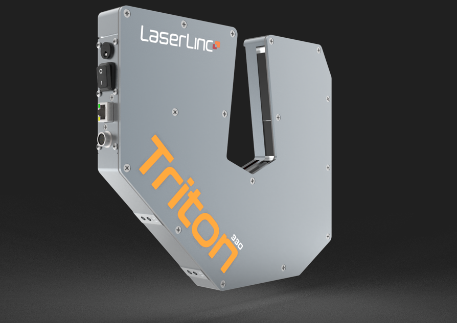
LaserLinc Triton triple-axis laser micrometers provide non-contact OD and ovality measurement for tubing applications where a more complete cross-sectional profile is needed.
Measuring Wall Thickness with Ultrasonics
Outside diameter is only one part of the story.
Ultrasonic measurement is used when manufacturers need to evaluate wall thickness, concentricity, or calculated ID without cutting the tube apart.
The basic principle is straightforward:
- A transducer sends a high-frequency sound wave toward the product.
- The sound wave generates echoes as it encounters the outer and inner surfaces of the tube.
- The system measures the time between those echoes.
- The software calculates the wall thickness using the acoustic velocity of the material.
LaserLinc ultrasonic systems use frequencies from 2.25 MHz to 50 MHz. Lower-frequency transducers are typically used for thicker walls and larger products. Higher-frequency transducers provide better resolution for thinner walls and smaller tubing.
LaserLinc has successfully measured polymer medical tubing walls as thin as 0.001 inches (25 μm) and metal nitinol stent tubing walls as thin as approximately 0.003 inches (75 μm).
Those values should not be treated as universal guarantees. Actual feasibility depends on the material, OD, wall range, surface condition, transducer style, acoustic coupling, alignment, and required repeatability.
For a fast initial review, use our Ultrasonic Wall-Thickness Feasibility & Transducer Selector. Enter the material, OD range, and wall-thickness range to identify a practical starting point for the frequency band and UltraGauge model. Final sensor selection should always be validated using representative samples.
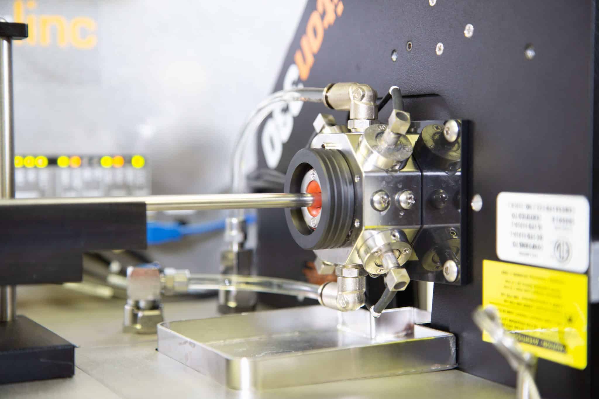
Close-up view of a metallic tubing sample positioned inside the LaserLinc BenchLincUT for offline ultrasonic wall-thickness measurement. Proper centering and stable alignment are important for repeatable results.
Why Calibration Matters
Ultrasonic thickness measurement is calculated from the travel time of a sound wave through the material.
That means the acoustic velocity used by the software matters.
Nitinol, stainless steel, and cobalt chromium should not be treated as interchangeable materials. The correct setup should be calibrated against a representative offline wall-thickness measurement before production inspection begins.
For demanding applications, calibration may need to be revisited when the material, product geometry, process condition, or inspection temperature changes.
The goal is not simply to generate a number on a screen. The goal is to confirm that the ultrasonic readings correspond to the actual part being measured.
What Does an Ultrasonic Feasibility Test Actually Involve?
A dimensional drawing is useful, but it does not always tell you whether a metallic tubing application can be measured reliably.
A proper feasibility test uses physical samples.
A typical evaluation includes:
- Selecting transducers based on the OD, wall-thickness range, material, and inspection goal.
- Centering the tubing within the ultrasonic fixture using appropriately sized guides or gaskets.
- Adjusting the acoustic velocity to align the ultrasonic measurement with an offline wall-thickness value.
- Reviewing the waveform for clear and consistent echoes.
- Adjusting signal-processing parameters such as gating, filtering, ringing interval, or offset when needed.
- Testing repeatability at the required measurement settings.
- Moving the part through the system to generate a continuous dimensional report.
In a recent nitinol sample evaluation, LaserLinc used four ultrasonic transducers around the circumference of the tube. The samples were centered within the measurement fixture, the waveform was calibrated against offline wall measurements, and continuous reports were generated as the tubes moved through the system.
That is the reality of ultrasonic measurement. The application is not validated by matching a wall thickness to a specification table alone. The signal needs to be evaluated using the actual product.
Measuring More Than an Average Wall Thickness
An average wall-thickness value does not always tell the full story.
A tube can meet its nominal wall specification while still containing variation around its circumference or along its length.
A multi-channel ultrasonic system can measure the wall at several positions around the tube, such as the top, bottom, left, and right sides. The software can then calculate:
- Individual wall measurements
- Average wall thickness
- Wall variation
- Concentricity
- Calculated ID
- Dimensional trends along the part
When the sample is scanned continuously, the result is a dimensional profile rather than a single spot-check value.
That makes it possible to identify localized thin spots or concentricity changes that may be missed when only a few positions are inspected.
Why Stable Guiding, Water Quality, and Air Bubbles Matter
Ultrasonic measurement depends on a stable acoustic path.
For inline or offline applications, the tubing needs to remain centered relative to the sensors. Unstable product movement, poor centering, or vibration can affect the waveform and reduce measurement consistency.
The water path also matters. Clean coupling water and proper bubble control help maintain a stable signal. Air bubbles, contamination, or debris near the transducer window can disrupt the acoustic path.
This becomes especially important for small metallic tubing and thin-wall applications, where the available signal may be more sensitive to setup conditions.
A well-designed ultrasonic system may include:
- Part-guiding blocks
- Roller guides
- Vertical and horizontal adjustment
- Controlled water levels
- Bubble-purge accessories
- Stable transducer positioning
These details are easy to overlook, but they are often the difference between an inconsistent test and a repeatable production measurement.
How Measurement Averaging Affects Repeatability
Ultrasonic systems can use measurement averaging to smooth natural variation in the signal.
Averaging multiple pings together can improve the stability of a wall-thickness reading. However, more averaging is not automatically better for every application.
There is a trade-off:
- Higher averaging can produce a smoother and more stable reading.
- Lower averaging can preserve more localized detail as the part moves through the system.
The appropriate setting depends on the tolerance, scan speed, part geometry, and whether the goal is a stable process trend or the detection of localized dimensional variation.
This is another reason sample testing matters. The measurement settings should be optimized for the actual inspection objective.
Raw Hypotube Is the Most Straightforward Application
Raw metallic hypotube is generally the cleanest ultrasonic application.
Before laser cutting or downstream processing, the sensor is measuring a continuous metal wall. This makes it possible to evaluate wall thickness and concentricity around the circumference and along the length of the part.
When an integrated laser micrometer is added, the same inspection station can also measure OD and ovality.
For incoming inspection, first-article validation, or lot sampling, the BenchLincUT offline inspection system can scan rigid metallic tubing and generate detailed dimensional reports.
What Changes After Laser Cutting and Encapsulation?
The measurement becomes more challenging after a hypotube has been laser cut and encapsulated in a polymer.
At that point, the ultrasonic signal is no longer passing through one uniform metallic wall. The sensors may encounter:
- Polymer-only regions
- Metallic struts or cut features
- Water-to-polymer interfaces
- Polymer-to-metal interfaces
- Additional internal layers
- Changing acoustic paths as the part moves through the fixture
In some applications, it may be possible to isolate the relevant polymer echoes and measure the encapsulated wall thickness or polymer layer thickness.
However, this should not be assumed from a drawing alone.
The metallic features may need to be excluded from the analysis so the software can focus on the relevant polymer readings. Signal gating and waveform filtering may be required. Feasibility depends on the laser-cut pattern, strut spacing, polymer thickness, layer construction, part diameter, and required tolerance.
For laser-cut, encapsulated, coated, or multilayer metallic components, physical sample testing is essential before selecting a final sensor configuration or making a capability determination.
Inline Measurement During Metallic Tubing Production
Offline inspection is often the best fit for incoming QC, laboratory validation, and completed tube-stick analysis.
However, manufacturers producing the raw tubing may benefit from in-process measurement.
LaserLinc UltraGauge systems provide live ultrasonic wall-thickness and concentricity data while the tubing moves through an appropriate stage of production. When paired with a Triton laser micrometer, the same inspection station can also provide OD, ovality, and calculated ID data.
Inline measurement gives operators faster feedback when dimensions begin to drift. Instead of producing material, cutting samples, and waiting for downstream results, the operator can see dimensional changes as they occur.
For metallic tube drawing, the best installation point needs to be reviewed carefully. The process may not resemble a typical polymer extrusion line. Some operations involve individual tube sticks, multiple drawing passes, lubricated surfaces, annealing, straightening, or finishing steps.
An inline ultrasonic station requires a suitable location where:
- The tube can pass through the measurement field consistently
- Stable alignment can be maintained
- Acoustic coupling is practical
- The surface condition supports a usable waveform
- The measurement provides meaningful feedback at that stage of production
For some metallic tubing lines, inline monitoring may be a strong fit. For others, offline scanning of finished tube sticks may be more practical.
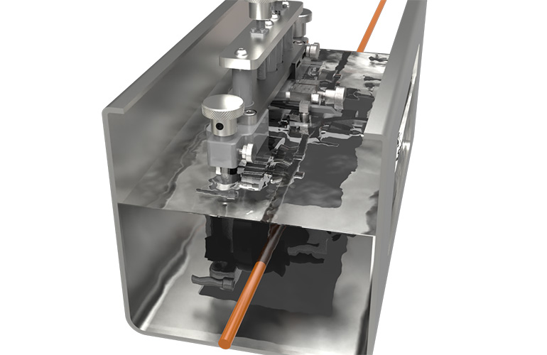
The LaserLinc UltraGauge system provides inline ultrasonic wall-thickness and concentricity measurement at an appropriate stage of the tubing production process.
Offline Inspection with BenchLincUT
BenchLincUT brings ultrasonic wall-thickness measurement into an offline inspection platform.
This is useful for:
- Incoming raw-material inspection
- First-article validation
- Lot sampling
- Process audits
- R&D
- Documented quality checks
- Tubing suppliers verifying finished tube sticks
- Medical-device OEMs inspecting tubing before laser cutting or assembly
BenchLincUT can evaluate wall thickness and concentricity around the tube while scanning along the sample length. An optional Triton laser micrometer adds OD and ovality measurement.
One practical limitation should be considered for shorter parts: fixtures, sensors, optional micrometers, and encoder wheels can create small unmeasurable regions near the leading and trailing edges of the sample.
Full-length scanning does not necessarily mean every point from the extreme front edge to the extreme back edge can be captured. The usable inspection length should be reviewed during system specification.
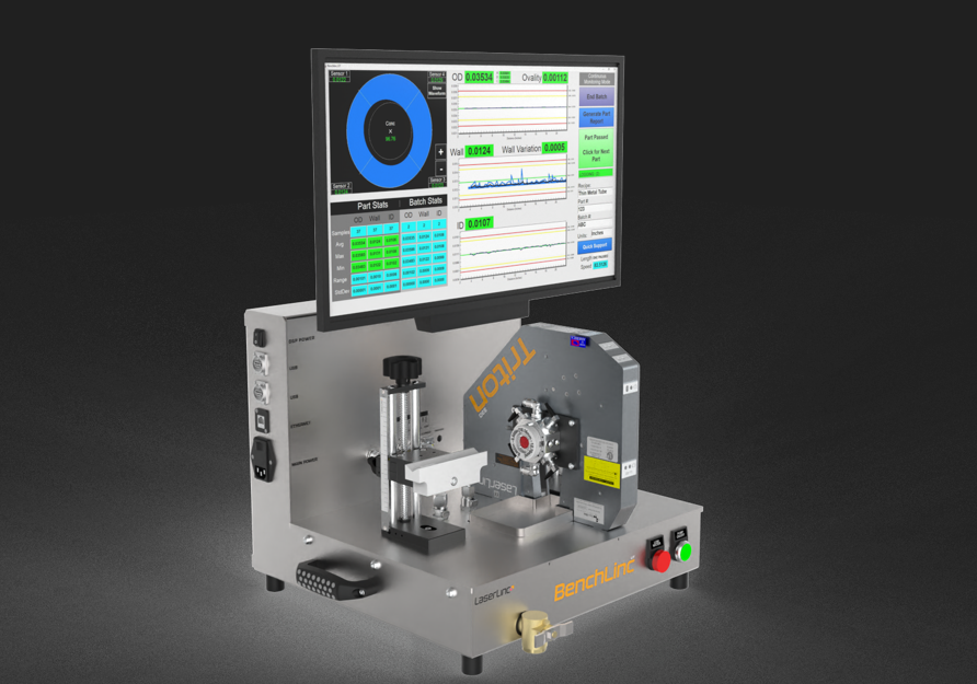
The LaserLinc BenchLincUT combines offline ultrasonic wall-thickness inspection with optional laser-based OD and ovality measurement for rigid metallic tubing applications.
See how the LaserLinc BenchLincUT scans rigid tubing samples to collect continuous dimensional data along the part length, including wall thickness, concentricity, OD, and ovality when configured with the appropriate sensors.
Connecting Inline Monitoring with Offline Validation
Inline and offline inspection do not need to be treated as competing approaches.
For tubing manufacturers, the strongest quality strategy may use both:
- UltraGauge for continuous inline process visibility
- BenchLincUT for offline validation and documented inspection
- UltraLinc software to associate inline readings with offline measurements
This creates a more complete validation loop.
Inline monitoring helps operators understand what is happening during production. Offline inspection provides a controlled reference measurement after the product has cooled or stabilized. Together, they provide better process visibility and a stronger quality record.
Which Measurement Strategy Fits Your Application?
| Inspection need | Practical starting point |
| Basic OD confirmation | Single-axis laser micrometer |
| OD and ovality measurement | Multi-axis laser micrometer |
| Nondestructive wall-thickness spot check | Ultrasonic measurement |
| Wall thickness and concentricity around the circumference | Multi-channel ultrasonic system |
| Inline process monitoring during tubing production | UltraGauge |
| Inline OD, ovality, wall thickness, concentricity, and calculated ID | UltraGauge plus Triton laser micrometer |
| Offline incoming inspection or sample validation | BenchLincUT |
| Laser-cut or polymer-encapsulated component inspection | BenchLincUT (Application-specific feasibility testing using physical samples) |
| Unsure which system architecture fits your process | Medical Tubing & Catheter Measurement System Selector |
Once dimensional data is being collected, the next question is whether the process is actually capable of holding the specification. Our Cpk and Ppk process capability calculator can help evaluate process centering and variation against your upper and lower specification limits.
You can also explore our full library of engineering calculators and industrial measurement tools for additional resources related to medical tubing, extrusion, dimensional inspection, and process improvement.
Need Help Measuring Metallic Medical Tubing?
Every tubing application is different.
Raw nitinol hypotube, stainless-steel cannulas, cobalt-chromium tubing, laser-cut structures, and polymer-encapsulated components each create their own measurement challenges.
The best starting point is to review:
- Material
- Minimum and maximum OD
- Minimum and maximum wall thickness
- Part length
- Tolerance
- Surface condition
- Raw versus processed state
- Inline versus offline inspection goal
- Representative sample availability
Gauge Advisor is the authorized sales and support partner for LaserLinc precision measurement systems. We help medical-device manufacturers and tubing suppliers evaluate laser and ultrasonic measurement applications, select the appropriate system configuration, coordinate sample testing, and support implementation.
Start by using our Ultrasonic Wall-Thickness Feasibility & Transducer Selector or Medical Tubing & Catheter Measurement System Selector.
For a detailed application review, quote, or sample test, feel free to reach out using the form below.

Founder, Gauge Advisor LLC