Film, Sheet & Blown Film Measurement and Control
Find thick and thin lanes, improve blown-film cooling, or stabilize tension and winding. Compare Scantech measurement and die control, Addex cooling and bubble control, and FMS web handling. A web is the continuous film or sheet moving through the line.
Gauge Advisor sells and quotes Scantech web gauging and die-control systems, Addex blown-film cooling and controls, and FMS tension and web-guiding equipment through the authorized manufacturer sales channel. Request equipment pricing with your process, project goal and facility location so I can confirm coverage and the right factory support.
 Scantech Web measurement & die control
 Addex Blown-film cooling & control
 FMS Tension measurement & guiding


What are you trying to improve?
Similar defects can come from different causes. Choose the closest problem first; then confirm the material, machine layout, speed, measurement range, and control hardware during application review.
See where the web is thick or thin
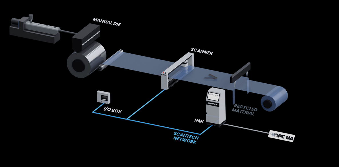
A Scantech scanner moves a compatible measurement head across the web and builds a side-to-side profile. This shows where material is being given away, where a thin lane may fail, and how the process changes over time.
- Best whenOffline samples arrive too late, average thickness hides local variation, or operators need continuous profile and trend data.
- MeasuresBasis weight (mass per unit area) and calibrated thickness; density, filler, or selected layer information depends on the material structure and calibration.
- SolutionULO3, HF3 and SHF3 cover different line-width and installation envelopes. Final selection also depends on geometry, material, environment and measurement scope.
iFit note: web width, thickness range, density changes, coating or layer structure, temperature, speed, available space, and the output you need all affect the configuration.
Turn profile data into automatic die correction
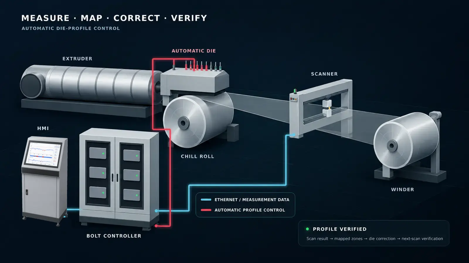
A scanner reveals the profile; it does not adjust the process by itself. On a compatible automatic flat die, the Scantech Bolt Controller 3 (BC3) maps thick and thin areas to the correct thermal die bolts and adjusts their qualified heater power or temperature.
- Best whenOperators repeatedly chase the same cross-direction bands, startup takes too long, or product changes require frequent die adjustment.
- ControlsCompatible thermal die-bolt zones for cross-direction profile correction; machine-direction average control is a separate function.
- SolutionScantech profile measurement, automatic mapping, and BC3 configured for the die and heater hardware.
iFit note: confirm die construction, bolt count and spacing, heater rating, how much the die can actually change the profile, profile-to-die mapping, and how quickly the polymer process responds.

Choose what the line needs to measure and what it needs to change
A blown film project may require profile measurement, external cooling, gauge profile correction, active IBC control, retained-air layflat control or downstream tension. Treat these as related but separate decisions.
- MeasureSelect a profile source and measurement location that match the machine. A traversing flat-web scanner is one possible system when the collapsed web is the preferred measurement point.
- Cool externallySelect the air ring, lip set, plenum, blower and cooling tier around the required output window, frost line and bubble support.
- Correct the profileMGC supports localized operator adjustment; EGC uses compatible mapped profile feedback to adjust external cooling automatically.
- Control bubble airDIBC coordinates active internal supply and exhaust on compatible IBC lines. BIDS adds or removes retained air on compatible non-IBC lines.
- Handle & windFMS measures and can control downstream tension when wrinkles, tracking, or roll formation are part of the problem.
iFit note: measurement location, profile mapping, die or haul-off movement, air delivery, IBC or retained-air bubble control, tower space and response time all affect the system. Also confirm that the root cause is not unstable extrusion, incorrect layer ratios, die damage or downstream tension.
Hold stable tension through processing and winding
Thickness tells you how much material is in the web. Tension tells you how strongly the web is being pulled. Stable tension helps reduce stretching, wrinkles, tracking problems, web breaks, and poor roll formation.
- MonitorFMS force sensors and measuring electronics send tension data to an operator, alarm, trend, or PLC.
- ControlA closed-loop controller can command a compatible brake or drive when automatic tension correction is required.
- Diagnose lanessegFORCE shows how tension is distributed across the width instead of returning only one average value.
iFit note: sensor size is based on force at the roller, not web tension alone. Entry and exit angles, wrap, roller weight, mounting, speed, and the shaft design must be reviewed.
Measurement and control are not the same thing
Clear roles make the system easier to specify: first measure the problem, then decide whether the line needs operator guidance, automatic correction, greater cooling, bubble-air control or steadier web handling.
Measure the profile
A scanner moves across the web and shows the cross direction (CD) profile, side to side. Machine direction (MD) means along the direction the web travels.
Correct the profile
A controller uses measured feedback to adjust a compatible actuator, such as automatic flat die bolts or localized air ring cooling zones.
Cool externally and control bubble air
Air rings cool and support the outside of the bubble. DIBC coordinates active IBC supply and exhaust. BIDS adds or removes retained air on compatible non-IBC lines.
Measure and control tension
Force sensors show how strongly the web is being pulled. Automatic correction needs suitable electronics plus a compatible brake or drive.
Different manufacturers solve different parts of the line
Scantech, Addex, and FMS solve different production problems. They can work together, but every line does not need all three. The right combination depends on the process, defect, machine layout, and available correction hardware.
Choose the process you want to see
Open one full-width animation at a time. Scantech shows cross-web measurement; Addex shows how blown film cooling and control functions fit together.
Loading the web-gauging overview…
If it does not load, review the web-gauging systems page.
Loading the blown film overview…
If it does not load, review the Addex air ring and control overview.
 Equipment optionsExplore equipment families and guided selectorsView Scantech, Addex, and FMS systems, with application-specific selection tools.View equipmentHide equipment
Choose the equipment by the job it performs
These are representative system families, not a substitute for sizing. Material structure, web width, range, line layout, speed, environment, interfaces, and the available actuator determine the final configuration.
Scantech: flat-web measurement, software & profile control
Use Scantech when continuous cross-web measurement must become usable production information. Scanner hardware captures the profile; FLEXSCAN organizes recipes, targets, alarms and operational roll views; TREX adds deeper report retrieval when included in the application package; and BC3 can close the loop on a compatible automatic flat die. Biax lines may use pre-stretch and final-film stations to understand how the profile changes through orientation.
Review the complete Scantech web gauging system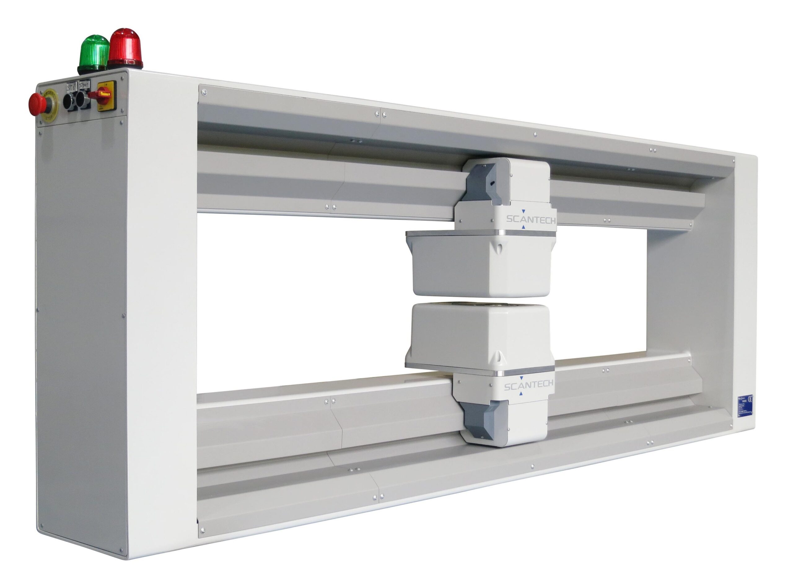
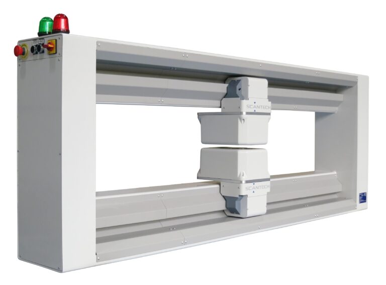
ULO3 cross-web scanner
The ULO3 moves a compatible measurement head across the web to reveal thick and thin lanes that a fixed reading or occasional offline sample can miss.
- Measures
- Mass per unit area and calibrated thickness; other outputs depend on material and calibration
- Best for
- Continuous film, sheet, selected coating and suitable post-layflat blown film profiles
- Range
- Supported web widths from 500 to 3,500 mm; wider frames are available
Bolt Controller 3 (BC3)
BC3 maps measured thick and thin areas to compatible automatic die bolts, then adjusts qualified heater power or temperature to reduce cross-direction profile variation.
- Controls
- Compatible thermal die-bolt zones; configurations are available for up to 360 bolts
- Best for
- Cast film and sheet lines with automatic dies and repeatable profile mapping
- Requires
- A compatible die, scanner profile, correct mapping, and sufficient process response

FLEXSCAN operator software
View live scanner profiles, trends, targets, tolerances, mapped zones and alarms, along with the configured control status.
- FLEXSCAN
- Runs recipes, operational profiles, alarms, current-profile export and configured roll or production views
- TREX
- Adds deeper browsing, tagging, sorting and retrieval of current and archived production reports when included
- Scope
- The application package and written quotation define the included software and reporting functions
Addex: blown film cooling, gauge & bubble control
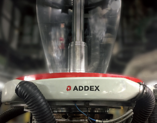
Use Addex when the line needs better external cooling, circumferential gauge profile correction, active internal cooling control or automatic layflat control without IBC. Start with the production problem, then coordinate the required equipment around the installed line.
Start with Addex blown film air rings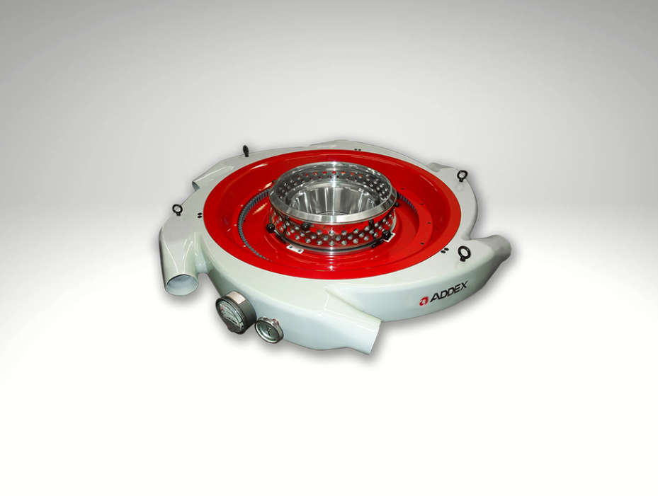
Air rings and external cooling
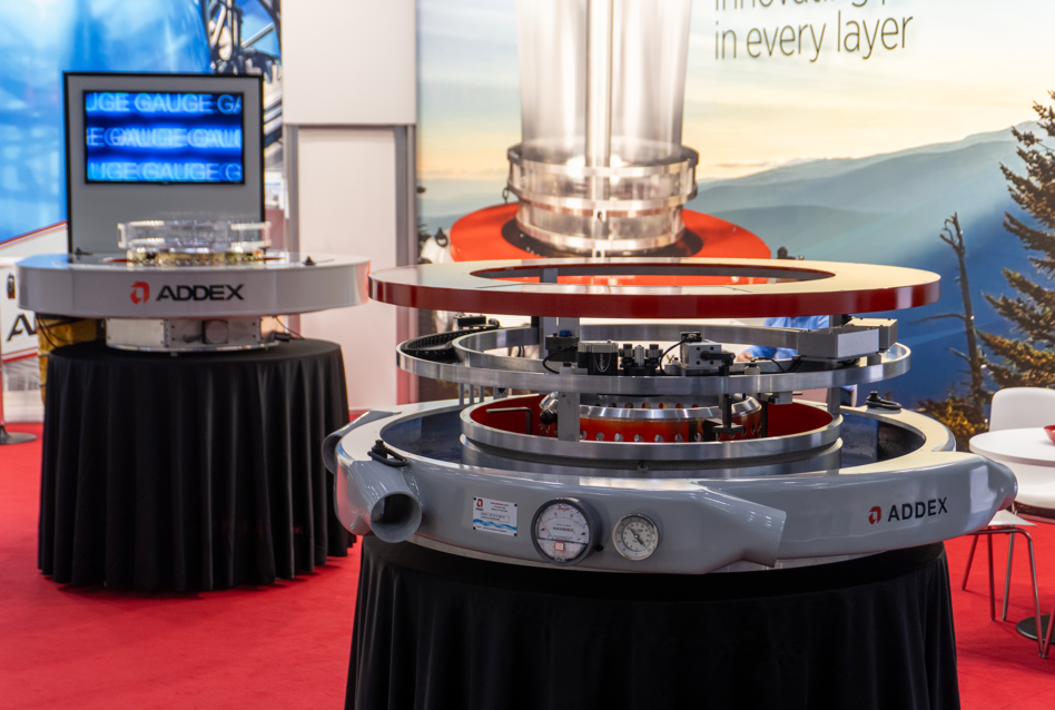
Start here for a replacement or retrofit air ring, LFR, qualified Intensive Cooling, lip and plenum changes, or a complete external cooling package.
- Use when
- Cooling capacity, frost line behavior, external bubble stability or the existing air ring is the question
- Review
- Resin, structure, output, blow up ratio, blower curve, ducting, tower clearance and product range

Manual and automatic gauge control
MGC provides manual local airflow adjustment. EGC uses a compatible total film profile and mapped external cooling correction for repeatable automatic control.
- Use when
- Repeatable circumferential thick and thin bands drive overgauge, scrap or operator adjustment
- Requires
- Correct profile mapping and movement feedback when the die, haul off or both move

Bubble size and layflat control
DIBC coordinates compatible active IBC supply and exhaust airflow. BIDS adds or removes retained bubble air on a compatible line without IBC.
- DIBC
- For a line with a usable internal cooling supply and exhaust path
- BIDS
- For automatic bubble size and layflat control on a compatible non-IBC line

Keep what works. Upgrade the constraint.
An air ring, IBC system, cage, blower, movement device, profiler or control platform does not always need to be replaced at the same time. A retrofit review documents the installed line, identifies the active production limit and organizes air rings, MGC or EGC, DIBC or BIDS, Cage Control and Gen3 into a practical phased path.
Review blown film line retrofit optionsWhich blown film solution fits this line?
Answer a few questions about the bubble, air ring, gauge profile, cooling limit and control goal to narrow air rings, MGC or EGC, DIBC, BIDS and installed-line modernization options worth reviewing.
FMS: web tension measurement, control & diagnostics
Use FMS to measure the pulling force on the web, send reliable data to the machine, regulate a compatible brake or drive, or reveal tight and loose lanes across the width.
Learn how web tension measurement works
CA-Series with measuring electronics
CA-Series force sensors mount at the ends of a compatible dead-shaft idler. FMS electronics convert the small load-cell signal into tension data for a display, alarm, trend, or PLC.
- Measures
- Total or average web tension through a compatible idler roller
- Best for
- Fixed-shaft rollers where the center shaft stays still and the outer shell rotates
- Requires
- Correct force range, web angles, roller weight, mounting, and signal electronics
Automatic tension control
An FMS controller compares measured tension with the operator's setpoint and commands a compatible brake or drive. This can keep tension steadier as speed or roll diameter changes.
- Controls
- A compatible unwind brake, rewind drive, or intermediate drive
- Best for
- Tension that drifts faster or more often than operators can correct consistently
- Requires
- Force sensors, controller, actuator, machine safeguards, and reviewed control logic
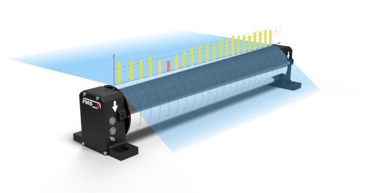
segFORCE cross-web tension profile
Two conventional end sensors report total or average tension. segFORCE provides independent readings across the width, exposing tight and loose lanes that an average can hide.
- Measures
- A cross-web tension profile with as many as 50 measurement positions
- Best for
- Baggy lanes, uneven slit rolls, wrinkles, coating defects, or acceptable average tension with poor roll quality
- Does not
- Mechanically correct those lanes by itself; it supplies diagnostic data
Which web-tension solution fits this machine?
Describe the roller, web route, tension range, control goal, and guiding needs. The tool can narrow dead-shaft, live-shaft, pillow-block, segmented, controller, and guiding options.
Compare measurement and control solutions
Use this table to understand the role of each family. “Automatic” means the complete system has measured feedback, compatible controls, and an actuator that can make the correction.
Comparison tableCompare measurement and control solutionsReview Scantech, Addex, and FMS by production problem, operation, and best fit.View tableHide table
| Solution | Primary problem | Where it works | What it does | Operation | Best fit |
|---|---|---|---|---|---|
| Scantech scanner + FLEXSCAN | Unknown or changing gauge profile | Moving flat webs, including suitable collapsed-layflat installations | Scans the cross-web thickness or basis-weight profile and presents profiles, trends, alarms and operational roll views | Measurement; TREX and control by scope | Continuous flat-web measurement and operator displays |
| Scantech biax gauging | Unclear origin of profile change through stretch | Cast-sheet, pre-stretch, post-stretch or final-film stations | Connects incoming basis weight, stretch stages, tenter-edge regions and final-film profile through a qualified mapping | Measurement and mapping; control by scope | BOPP, BOPET, BOPE and BOPA orientation lines |
| Scantech scanner + BC3 | Cross-direction gauge variation | Compatible automatic flat die | Maps profile positions to thermal die bolts and corrects the die zones | Automatic CD control | Cast film and sheet profile control |
| Addex MGC | Repeatable blown film gauge bands | External air ring | Lets an operator adjust localized cooling zones | Manual | Cost-conscious profile improvement with trained operators |
| Addex EGC | Persistent blown film gauge profile variation | External air ring | Uses compatible mapped thickness profile feedback to adjust localized external cooling | Automatic | Closed loop blown film gauge profile correction |
| Air Rings / Intensive Cooling | External cooling, output or bubble support limitation | External air ring and qualified air delivery package | Matches external airflow and cooling capacity to the line; it does not measure thickness | Engineered cooling package | Replacement, retrofit or cooling limited blown film lines |
| Addex DIBC | Active IBC airflow, bubble size or layflat instability | Compatible line with internal supply and exhaust airflow | Coordinates active internal cooling supply and exhaust using bubble feedback | Automatic bubble air control | Compatible IBC lines needing repeatable layflat response |
| Addex BIDS | Bubble size or layflat drift without IBC | Compatible retained-air blown film bubble | Adds or removes contained bubble air to maintain the layflat target | Automatic inflate / deflate | Compatible non-IBC lines using retained bubble air |
| FMS CA + electronics | Tension drift and roll defects | Compatible dead-shaft idler roller | Measures total tension; a controller can command a brake or drive | Monitoring; automatic with controller | Fixed-shaft roller layouts |
| FMS segFORCE | Baggy lanes or uneven cross-web tension | Full-width measuring roller | Measures independent tension positions across the width | Diagnostic monitoring | Wide webs, coating, laminating, slitting, and winding |
Application note: On blown film lines, select the measurement location and correction system as two related decisions. Addex EGC requires compatible mapped profile feedback; Scantech post-layflat scanning is one available system when the collapsed web is the appropriate measurement point. Line layout, movement, response time, interfaces and available correction hardware require review.
Built around the process and material
The same symptom can require different sensors or controls on a blown film line, flat-die extrusion line, orientation line, coating line or rewinder.
Blown film
Start with the actual constraint: external cooling, gauge profile, active IBC airflow, retained-air layflat, startup waste or downstream winding. Select the measurement location separately, then route the Addex scope to the correct focused system. For an older or mixed-OEM line, begin with the phased retrofit plan.
Explore Addex air rings and controlsCast film & sheet profile control
Track cross-web thickness continuously, reduce resin giveaway, shorten startup, and use BC3 automatic thermal-die correction when the die, mapping and control authority are compatible.
Explore automatic thickness profile controlSheet & thermoforming
Control thick and thin lanes before they become uneven heating, forming variation, part-weight drift, or avoidable trim and resin waste.
Explore film and sheet web gaugingBiax film: BOPP, BOPET, BOPE & BOPA
Use qualified pre-stretch and final-film stations to see incoming cast-sheet basis weight, follow profile change through MDO and TDO, and resolve profile detail near the tenter-clip grip regions. ULO3, HF3 or SHF3 is selected around line width, installation geometry and measurement scope.
Explore biax film thickness measurementFoam & filled structures
Determine whether the process needs thickness, mass per unit area, density, filler, or another calibrated output. Material composition and calibration determine what can be separated reliably.
Review material measurement optionsExtrusion coating & lamination
Measure coating or combined web properties while keeping stable tension through nips, dryers, chill rolls, laminators, and winding. The correct sensor depends on the layer structure.
Review web coating measurement systemsSlitting, rewinding & converting
Use total tension for machine control and segFORCE when an acceptable average still hides tight edges, loose lanes, uneven slit rolls, or localized winding defects.
Explore cross-web tension profilingExplore in more detailTrace the problem through the lineCompare common symptoms, likely causes, and useful measurements.View detailsHide details
Similar defects can have different causes
Start with evidence, not assumptions. A thickness scanner, tension trend, cross-web profile, bubble observation, and machine drawing can prevent an expensive fix from being aimed at the wrong part of the line.
Thick or thin lanes
Possible causes: material flow, die behavior, profile mapping, cooling distribution, or a process disturbance that repeats across the width.
Resin giveaway
Possible causes: unstable profile, delayed feedback, overly conservative target thickness, or operators protecting against thin spots they cannot see continuously.
Wrinkles or telescoping
Possible causes: tension, guiding, thickness variation, roll geometry, nip settings, air entrainment, or winding setup.
Baggy edges or loose lanes
Possible causes: cross-web tension distribution, raw-material behavior, gauge profile, temperature history, or prior stretching.
Slow startup
Possible causes: delayed measurement, manual sampling, slow mapping, conservative operator adjustments, or a control response that has not been tuned.
Unstable layflat
Possible causes: on an active IBC line, review internal supply and exhaust response and the DIBC control system. On a retained-air line, review inflate and deflate behavior and BIDS. External cooling, cage or collapsing frame setup, line speed and downstream tension may also contribute.
Choose what operators see and what the system records
Define who needs the measurement, how quickly they need it, what should be stored, and which device is allowed to make an automatic correction.
FLEXSCAN & TREX
FLEXSCAN runs recipes, live profiles, alarms, current-profile export, configured control visibility and operational roll views. TREX works alongside it for deeper current and archived report retrieval when included; the application package and quotation define the scope.
Explore Scantech software functionsAddex mapping & control
EGC relates compatible measured profile data to physical air ring zones and tracks the applicable moving coordinates. DIBC and BIDS are separate bubble-air functions; neither is the gauge profile actuator.
FMS measuring electronics
Convert small load-cell signals into usable tension data for displays, analog outputs, industrial networks, alarms, trends, and PLCs.
Closed-loop control
Measured feedback is compared with a target, then a compatible die zone, air-ring zone, brake, or drive is adjusted. Safeguards and machine ownership must be defined.
Crayex: improving gauge control on an existing line
An Addex-published Crayex case study describes an EGC air-ring retrofit for a blown film line with a rotating or oscillating die. Crayex reported improved thickness consistency and lower scrap, restoring the line’s ability to run products that had been difficult to schedule.
Review the project details and reported results, then share your die, air-ring configuration, and current profile problem to evaluate the fit for your line.
Start with three details about your line
Tell us the process and material, the approximate width and line speed, and what needs to improve. You can start before the full specification is ready. Open the detailed checklist for your application when needed.
Detailed application checklistsChoose a checklist for thickness and die control, blown-film cooling, or tension and guiding.
Thickness, biax measurement & die control
- Material and layer structure
- Target thickness, range, and tolerance
- Web width, speed, temperature, and environment
- Scanner locations, measured widths and available space
- For biax lines: stretch sequence, station widths, tenter-grip regions, trim rules and process delay
- For BC3: die type, bolt count, zone spacing, heater data and approved actuator interface
- Required FLEXSCAN views, TREX reporting scope, alarms, roll identifiers and plant interfaces
Blown film cooling, gauge & bubble control
- Die and air ring make, size and photographs
- Bubble diameter, layflat, blow-up ratio and frost line range
- Materials, layer structure, output and cooling limits
- Profile data and the defect you are trying to reduce
- Current controls generation plus panel and nameplate photos
- Active IBC or retained-air bubble arrangement
- Blower, duct, supply and exhaust, or inflate and deflate path
- Stationary, rotating or oscillating movement and position feedback
- Cage, collapsing frame and tower clearances
Web tension & guiding
- Minimum and maximum web tension
- Web width, speed, material, and environment
- Entry and exit angles plus roller wrap
- Roller weight, diameter, shaft design, and mounting
- Monitor-only or automatic-control goal
- Brake, drive, PLC, network, alarm, and guiding requirements
Short demonstrations for the three solution areas
These videos show the equipment and process context without loading embedded players on the page.
Scantech extrusion measurement
See how inline scanning and profile software fit into film and sheet extrusion.
Watch the Scantech overviewAddex blown film control
See Addex blown film cooling, gauge profile and bubble control equipment in its production context.
Watch the Addex overviewFMS segFORCE
See how segmented measurement reveals tension differences across the web that conventional averages can hide.
Watch the segFORCE overviewRelated film & sheet process systems
Thickness and tension data show the result, but upstream material feed, melt delivery, reclaim, and coating processes determine what reaches the web.
Film & sheet melt pumps and filtration
Review melt-pressure stability, filtration, screen changing, and downstream flow control.
Review melt delivery ABS reclaimInline film scrap repelletizing
Return qualified clean edge trim or roll scrap through a controlled pellet-recovery system.
Review film scrap recovery ABS rate controlGravimetric extrusion throughput control
Measure actual resin consumption and coordinate screw speed, layer ratio, or line speed by scope.
Review weigh hoppers Coating and laminationContinuous-web coating measurement
Connect film and sheet production to inline coating weight, thickness, and process-control requirements.
Review web coating systemsUseful selection and planning tools
Use the tools to organize the process details before an application review. Final equipment selection still requires drawings, sizing, compatibility review, and sometimes sample testing.
Blown Film Air Ring & Control Selector
Organize air ring, MGC or EGC, DIBC or BIDS, and installed line retrofit considerations.
Use the embedded selector SelectorWeb Tension & Guiding Selector
Review roller construction, force range, electronics, automatic control, segmented measurement, and guiding.
Use the embedded selector ROIWeb Gauging ROI Calculator
Estimate the value of reduced resin giveaway, startup scrap, off-spec production, and delayed quality feedback.
Estimate web-gauging ROI CalculatorFilm Thickness Converter
Convert common film-thickness units without rebuilding the calculation in a spreadsheet.
Open the thickness converter CalculatorExtrusion Throughput & Line Speed
Relate output, product dimensions, density, and line speed during a preliminary process review.
Open the line-speed calculator ROIBlown Film Air Ring ROI Calculator
Estimate whether cooling, gauge improvement, output and startup savings justify an air ring upgrade.
Estimate air ring ROIReferenced in Packaging Strategies
Packaging Strategies references Gauge Advisor's blown-film gauge variation guide in its article on multilayer coextrusion. The guide helps teams organize the causes of thickness variation before selecting measurement or control equipment.
Film, sheet, blown film and web tension FAQs
Plain-language answers to the questions that most often change the equipment recommendation.
What is the difference between thickness and basis weight?
What do cross direction and machine direction mean?
Does an inline scanner automatically control the die?
What is the difference between FLEXSCAN and TREX?
When should I choose Addex MGC instead of EGC?
How is thickness measurement selected for blown film gauge control?
What is the difference between DIBC and BIDS?
Can an air ring upgrade increase blown film output?
Does web-tension control fix thickness variation?
What is a dead-shaft roller?
Is the FMS CA-Series the right sensor for every web line?
Why use segFORCE instead of two conventional load cells?
Can Scantech measure every individual layer in a multilayer film?
How is biax film measured before and after stretch?
What information is needed for a recommendation?
Gauge Advisor provides authorized Scantech, Addex, and FMS sales and applications support. Final selection depends on the material, line layout, and compatible measurement or control hardware.
Inline thickness measurement with optional profile control
Measure the profile. Correct the process.
The scanner maps thick and thin areas across the web. In this configured example, BC3 adjusts the corresponding die zones and later scans verify the result.
Explore web gauging systems