Updated August 21, 2026
When a blown film line cannot hold more pounds per hour, the extruder often gets blamed first. Yet the first limit may be external cooling, bubble stability, internal bubble cooling, gauge giveaway, airflow distribution, operator dependence, or downstream handling. The right upgrade starts by identifying what changes first as output rises.
Connected process path: The fastest route to more blown-film output is to identify whether the active limit is material feed, melt delivery, cooling, gauge control, or scrap recovery.
Related next steps: continuous gravimetric blenders, throughput-control weigh hoppers, film-scrap repelletizing, film and sheet melt delivery, and blown-film gauge control.
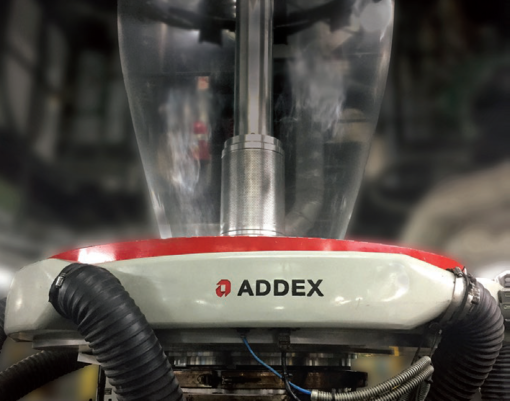
Seven bottlenecks that can cap blown film production
Select a bottleneck to compare the visible symptoms, the first checks to make, and the Addex equipment path that may be relevant. The equipment path is intentionally shown after the diagnostic checks.
1. Cooling capacity: the bubble cannot reject heat fast enough
As output rises, more heat enters the bubble each hour. If the cooling system cannot remove it, the frost line moves upward, the unsupported hot length grows, and the operator eventually reduces rate to recover stability.
Higher frost line, hotter film, less stable bubble, haze or blocking risk, and a repeatable output ceiling.
Blower operating point, filters, duct losses, air temperature, lip settings, die temperature, tower space, and takeoff capacity.
Evaluate LFR or SIP for the cooling baseline, then Intensive Cooling or Short Stack when external cooling is the verified limit.
Have a blown film bottleneck worth reviewing?
Tell us your die diameter, current output, and what prevents the line from running faster or more consistently. Gauge Advisor can help assess whether Addex cooling, gauge control, or a coordinated retrofit addresses the limiting condition.
What changes first when you push the line?
This short tool narrows the most likely starting path. It does not replace review of the die, blower, IBC, material structure, tower, controls, scanner, and downstream equipment.
How to diagnose and remove each bottleneck
This article is intentionally more focused than a full cornerstone troubleshooting guide. Each section covers one production limit, the evidence that supports it, and the most logical Addex path when equipment is part of the answer.
Cooling capacity reaches its limit
Every additional pound per hour adds heat that must be removed before the tube can be collapsed and wound. A higher frost line is not automatically bad, but a frost line that keeps climbing as output rises is a strong clue that the cooling system is losing margin.
The line reaches a repeatable output ceiling, the frost line rises, film temperature increases, bubble motion grows, or the operator must reduce rate to restore stability.
Record blower pressure and flow, filter condition, air temperature, duct restrictions, air-ring settings, die temperature, frost-line height, tower clearance, and downstream capacity.
Start with the correct LFR, MGC, EGC, or SIP architecture. Add Intensive Cooling or Short Stack only after confirming the extruder, blower, die, IBC, tower, and winder can support the added rate.
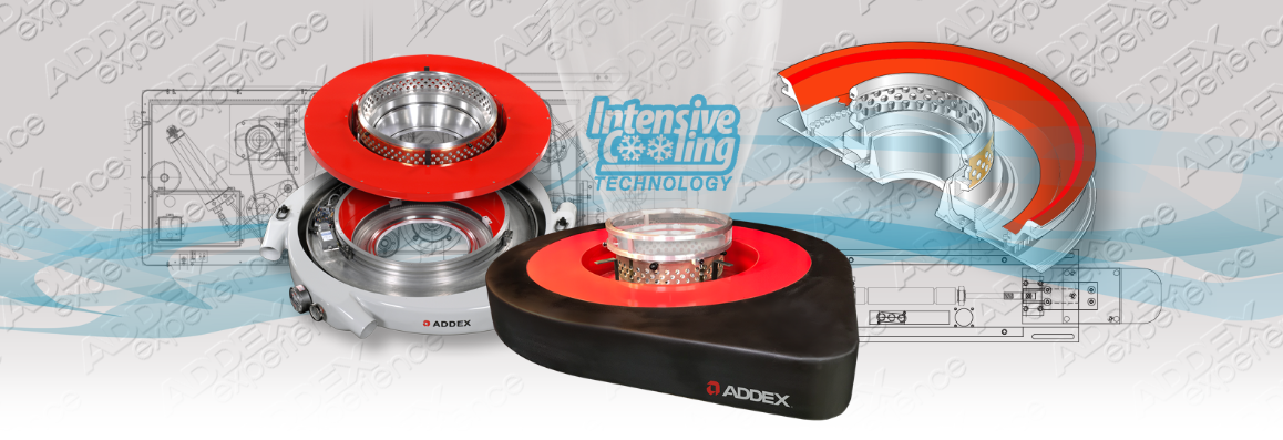
Addex currently publishes a 10% to 15% output increase for qualifying upgrades from an Addex standard air ring to an Addex Intensive Cooling air ring. Addex also publishes higher Short Stack gains for qualifying retrofits. Those are manufacturer performance claims tied to the actual application, not a universal forecast for every line.[1]
Bubble stability becomes the rate limiter
A line may have enough melt and blower capacity on paper but still be unable to hold the bubble at the next production rate. The unsupported hot length, material melt strength, BUR, air-ring lock points, room drafts, cage contact, and IBC response all affect the operating window.
Flutter, oscillation, breathing, frost-line movement, layflat drift, frequent cage adjustment, or a sudden increase in thickness variation as output rises.
Trend layflat, frost line, output, external airflow, IBC supply and exhaust, cage position, room conditions, material lot, and the exact rate where instability begins.
Intensive Cooling adds an earlier high-velocity stabilization point. Digital IBC addresses internal airflow and layflat response. Short Stack provides a higher-output stabilization architecture for qualifying lines.
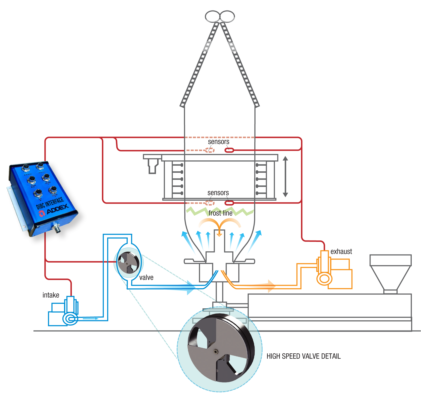
Addex Digital IBC uses sensor information below and above the frost line to detect and correct bubble-size changes earlier in the process. This is most valuable when internal cooling and layflat control are part of the limit, not simply because an IBC system is present.[4]
Gauge variation turns output into resin giveaway
A line can make more pounds per hour and still fail to create more profitable film. When the cross-direction profile is wide, operators often raise the average target to protect the thinnest zones. The result is more resin in every roll than the customer requires.
Persistent thick and thin bands, high profile sigma, heavy rolls, a target above nominal, slow manual corrections, or good average thickness with poor minimum thickness.
Separate machine-direction changes from circumferential profile. Confirm die and air-ring centering, lip condition, airflow, rotation mapping, scanner correlation, and the actual variation calculation.
MGC provides manual local airflow correction. EGC uses mapped online profile data for automatic high-resolution correction. Gen3 controls support selected rotating-die applications.
Addex publishes customer thickness-variation reductions of 20% to 30% for MGC and a 50% or greater target for EGC. Treat these as manufacturer-published application examples and validate the expected result from actual profile data, die condition, measurement architecture, and product mix.[2][3]
Air distribution creates a hidden cooling imbalance
Unequal hose lengths, tight bends, restrictions, dirty filters, plenum turbulence, lip contamination, and room air can create circumferential cooling differences before any automatic control begins working.
A fixed profile band, uneven frost line, local bubble movement, repeated inlet effects, difficult hose access, or different results after hoses are moved.
Inspect every hose, filter, damper, plenum, lip, vane, seal, and room draft. Compare pressure at the air ring with blower discharge rather than assuming the duct delivers what the blower produces.
Addex SIP uses one external connection and dual counterflow distribution to reduce hose variation and common inlet effects. It is available with Intensive Cooling and for rotating or stationary dies.
A better starting profile reduces the amount of correction an MGC or EGC system must apply. Air distribution and automatic gauge control should be reviewed together rather than treated as unrelated upgrades.[5]


IBC and layflat control cannot keep up
Internal Bubble Cooling adds heat-removal capacity and controls bubble size, but an older or poorly tuned IBC system can become its own bottleneck. A slow response can create breathing, layflat variation, long changeovers, and excess scrap while the line settles.
Layflat oscillates, internal pressure changes slowly, the bubble moves before the controller reacts, changeovers take too long, or the process is sensitive to air temperature.
Trend supply, exhaust, valve position, layflat, frost line, cage position, nip condition, sensor calibration, leaks, and response after a controlled setpoint change.
Digital IBC is the main Addex path when internal cooling, bubble-size feedback, and faster layflat response are limiting production or changeovers.
Addex publishes an optional quick-change feature that can reduce changeover time by 50% or more on qualifying applications. That claim should be evaluated against the current startup method, recipe range, valve architecture, and actual scrap window.[4]
Operator workload and fragmented controls reduce repeatability
A line that depends on one experienced operator can appear capable during one shift and unstable during the next. Manual samples, die rotation, bubble size, cage position, IBC, profile correction, and alarm response may all be managed separately.
Different results by shift, repeated adjustments before the last change settles, long startup, undocumented setpoints, and frequent intervention after material or speed changes.
Measure time to first saleable roll, number of manual corrections, scrap pounds, recipe changes, alarm frequency, and whether all controls share the same speed and position data.
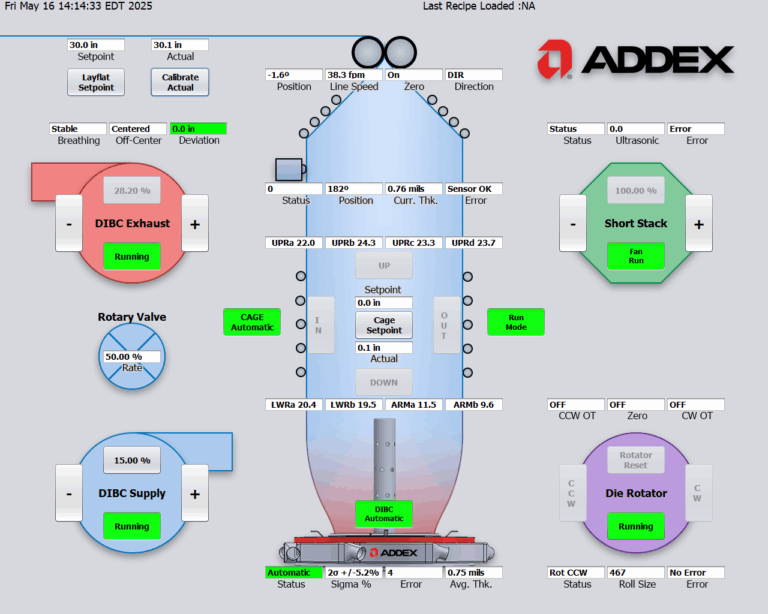
Generation 3 control can coordinate EGC, DIBC, bubble inflation or deflation, cage functions, rotation mapping, and related modules within one control architecture.
Automation should reduce decision load, not hide the process. The best control architecture still gives maintenance and operations clear status, manual recovery, documented recipes, and access to the variables that explain why the line changed.[3]
The real bottleneck is not the air ring
This is the most important diagnostic point in the article. A line may appear cooling-limited when the actual limit is feed consistency, melt pressure, filtration, die condition, tower geometry, scanner delay, tension, guiding, winding, or the market demand for the added output.
Melt pressure rises or surges, motor load reaches a limit, feeder output changes, screen pressure climbs, gels increase, or average thickness moves before the bubble changes.
The profile is stable but rolls wrinkle, telescope, wander, block, or develop hard and soft lanes as rate rises.
Use Addex when cooling, airflow, bubble stability, IBC, or polar gauge control is the verified limit. Use the appropriate Gauge Advisor melt, measurement, or web-handling path when another section of the line reaches its limit first.
Scantech measurement can confirm thickness profile and timing after the layflat. FMS tension and segmented cross-web measurement can separate a stable gauge profile from poor web handling. MAAG melt-pump and filtration tools can help when pressure, gels, or screen-change disturbance are limiting the line. These systems solve different problems.
Match the Addex technology to the verified bottleneck
These are starting architectures, not final model selections. Die size, material, BUR, thickness, output, blower data, IBC, tower layout, die motion, scanner, and control requirements determine the final configuration.
LFR and SIP
Best fit: improve the external cooling platform, airflow uniformity, access, and bubble stability without automatic profile control.
Review: rotating or stationary die, hose layout, blower, lip set, and required air conditions.
Intensive Cooling
Best fit: the line is externally cooling-limited and has enough extruder, blower, IBC, tower, and downstream capacity to use added output.
Available with: LFR, MGC, and EGC architectures.
Short Stack
Best fit: qualifying lines needing substantially more cooling and stabilization than a conventional down-on-the-die architecture.
Review: material melt strength, die size, IBC, blower, extruder, tower, and startup method.
MGC
Best fit: repeatable circumferential gauge bands where manual sampling and adjustment remain acceptable.
Review: die motion, sample orientation, operator method, correction range, and required response time.
EGC and Gen3
Best fit: automatic correction of mapped polar profile with online thickness data, including selected rotating-die applications.
Review: scanner profile, mapping, transport delay, die or haul-off position, and stable average output.
Digital IBC
Best fit: internal cooling, bubble-size response, layflat stability, and changeover time are limiting production.
Review: supply and exhaust capacity, valve, sensors, leaks, nip, air temperature, and control integration.
Use the 60-Second Blown Film Air Ring Selector to organize the first application path. Use the Air Ring ROI Calculator after the current loss and realistic improvement range are defined.
Measure the bottleneck before calling the project successful
Output alone is not enough. A useful baseline should show whether the added pounds are saleable, whether the bubble is more stable, whether gauge giveaway falls, and whether the downstream process can handle the new rate.
- Product rangeResins, layer structure, thickness, layflat, BUR, die size, output, and changeover range.
- Current air ringManufacturer, model, lip set, plenum, hose count, inlet sizes, age, condition, and current settings.
- Blower and ductBlower curve, motor, VFD, discharge pressure, air temperature, filters, duct lengths, bends, dampers, and measured ring pressure.
- IBC and bubble controlSupply, exhaust, valve, sensors, layflat control, cage, leaks, nip, and location of the frost line.
- Gauge and mappingScanner type, measurement location, profile plots, scan time, deconvolution, die motion, encoder, and control delay.
- Upstream processExtruder size, screw speed, motor load, melt pressure, screen changer, filtration, melt pump, feeder, blender, and resin changes.
- Downstream limitTower, collapsing frame, nips, treatment, tension, guiding, winder, roll quality, and maximum mechanical speed.
- Economic targetCurrent scrap, resin giveaway, saleable output, downtime, changeover loss, resin value, contribution margin, and annual hours.
Use the Extrusion Throughput and Line Speed Calculator to relate line speed and output. Use the Cpk/Ppk Calculator to compare process capability before and after the change. When the measurement or web-handling layer is unclear, review the Web Gauging Technology Guide and the Web Tension and Guiding Selector.
Related Gauge Advisor blown film resources
These pages connect output bottlenecks to the deeper cooling, gauge-control, measurement, tension, melt-delivery, and ROI paths.
Blown film production bottleneck FAQs
How do I know whether cooling is the real blown film bottleneck?
Increase output in controlled steps while recording frost-line height, layflat, bubble motion, blower conditions, film temperature where useful, gauge profile, and downstream behavior. Cooling is a strong candidate when the frost line and unsupported hot length rise, stability margin falls, and the extruder still has capacity. Confirm that the blower, duct, IBC, tower, and winder are not the actual limit.
Does more blower airflow always increase output?
No. Useful cooling depends on the blower operating point, pressure at the air ring, air temperature, duct losses, lip geometry, flow distribution, bubble lock points, and process stability. More flow can create turbulence or move the operating point without improving heat transfer.
What is the difference between Addex Intensive Cooling and Short Stack?
Intensive Cooling integrates an additional high-velocity cooling and stabilization element into the air-ring architecture. Short Stack adds a higher-output stacked cooling arrangement for qualifying lines. The correct path depends on the material, die, IBC, blower, extruder, tower, and output target.
When should I consider Addex MGC instead of EGC?
MGC is an economical path when the profile problem is repeatable and manual sample-based correction is acceptable. EGC is the automatic path when the line needs mapped online profile data, closed-loop correction, faster response, recipe repeatability, or less operator dependence.
Can Addex EGC work with a rotating die?
Addex offers a Gen3 EGC architecture for supported rotating-die applications. Final compatibility depends on the existing die motion, drive, position feedback, scanner, controller, profile mapping, line layout, and die size.
When is Digital IBC the better first upgrade?
Digital IBC becomes the stronger first path when the internal cooling system, bubble-size response, layflat stability, or changeover time is limiting production. It is not a substitute for external cooling when the air ring is already at its limit.
What should I send for an Addex application review?
Send die size, resin and layer structure, layflat and BUR range, current and target output, thickness range, air-ring information, blower and duct data, IBC details, frost-line photos, profile plots, die or haul-off motion, tower and winder limits, and the current economic loss. Better data produces a more useful equipment recommendation.
References and source notes
The references are collapsible to keep this focused seven-point article readable. They open automatically when printing.
Open technical references and source notes11 sources
Gauge Advisor is the authorized Addex sales and applications support partner. Addex sources are used for current product architecture and published performance statements. Independent resin-producer guidance, ASTM measurement guidance, and official Scantech and FMS material provide broader technical context. No competing blown film cooling, gauge-control, web-gauging, or tension-equipment suppliers are cited.
- Addex, Intensive Cooling Datasheet. Current manufacturer information on icLFR, icEGC, SIP availability, cooling-air requirements, published output gains, Short Stack architecture, and the requirement for sufficient extruder and blower capacity.
- Addex, Manual Gauge Control Air Rings. Manufacturer description of MGC, manual high-resolution airflow correction, published customer variation reductions, and Intensive Cooling availability.
- Addex, External Gauge Control. Manufacturer description of EGC airflow correction, mapped profile control, Generation 3 modular controls, current control-zone ranges, and rotating-die availability.
- Addex, Digital Internal Bubble Cooling. Manufacturer information on below- and above-frost-line sensing, internal airflow control, layflat stability, integration, and optional quick-change architecture.
- Addex, Single Inlet Plenum. Manufacturer description of the single external connection, dual counterflow internal distribution, reduced inlet effects, and compatibility with Intensive Cooling and rotating or stationary dies.
- Addex, Intensive Cooling Short Stack. Manufacturer description of the stacked high-output architecture, stabilization points, startup approach, and published retrofit performance ranges.
- Addex, Gen3 EGC for Rotating Dies. Manufacturer description of coordinated die rotation, mapped profile correction, and modular Generation 3 control for selected rotating-die retrofits.
- LyondellBasell, How to Solve Blown Film Problems. Non-equipment-supplier troubleshooting guidance covering cooling, frost line, bubble instability, gauge bands, drafts, die and air-ring alignment, and winding symptoms.
- LyondellBasell, A Guide to Polyolefin Film Extrusion. Broad process context on resin, extruders, dies, air rings, IBC, towers, gauging, haul-off, and winding.
- Scantech, Measurement Systems for Blown Film Lines. Official description of layflat X-ray measurement, double-layer deconvolution, thickness profile, and control mapping used to verify gauge-control performance.
- FMS, segFORCE Segmented Tension Roller. Official description of cross-web tension measurement used to distinguish downstream tension distribution from thickness-profile problems.
Review the Addex application before choosing the air ring
Gauge Advisor is the authorized Addex sales and applications support partner for blown film air rings, Intensive Cooling, Manual Gauge Control, External Gauge Control, Digital IBC, and related controls. I help blown film processors evaluate the equipment application, organize the line data, select and quote the appropriate Addex architecture, coordinate factory engineering, and support integration and ongoing application questions.
Gauge Advisor supports equipment selection and integration for the manufacturers represented here; independent process consulting is not offered. Send the line data, current equipment, profile plots, material structure, output target, and the problem you are trying to solve. I will respond within one business day, often within a few hours.
- Air ring, SIP, and Intensive Cooling review
- MGC, EGC, and rotating-die profile-control review
- Digital IBC and bubble-control review
- Blower, duct, tower, scanner, and retrofit data coordination
- Quotations and Addex factory application review
- Ongoing sales and applications support