Updated August 21, 2026
The best web gauge starts with the measurement you actually need, not with the sensor name. A film processor may say “thickness” while the process really needs basis weight, density, coating add-on, a cross-web profile, or a control signal tied to the die. Those are related measurements, but they are not interchangeable.
This guide compares the main web gauging technologies used on film, sheet, extrusion coating, adhesive coating, paper, nonwovens, battery electrodes, composites, fuel-cell materials, and other continuous roll-to-roll lines. It also explains what each technology sees, where it can be misled, how to read machine-direction and cross-direction patterns, and what information should be reviewed before a system is quoted.
Connected process path: Select web gauging as part of the line architecture: sensor physics, scanner geometry, process stability, web handling, and the actuator that will use the measurement.
Related next steps: film and sheet measurement systems, X-ray transmission web gauging, battery-electrode coating measurement, web tension and guiding selector, and film and sheet melt delivery.
What are you actually trying to measure?
“Gauge” is often used as a catch-all term. Before comparing sensors, separate the physical property, the reporting unit, and the process action that will use the result.
The distance between two surfaces, usually reported in microns, mils, millimeters, or inches. Optical and laser methods measure geometry directly. Transmission systems can report thickness when material density and composition are sufficiently known and calibrated.
thickness = basis weight ÷ densityThe amount of material per unit area, typically g/m². This is often the most meaningful production variable for paper, nonwovens, coatings, foam, and filled webs. TAPPI T 410 defines grammage as mass per unit area for paper and paperboard.[6]
basis weight = mass ÷ areaThe mass or thickness added to a substrate. When substrate variation is significant, measuring the substrate before coating and the total web after coating can be more reliable than assuming a constant base. Time registration or “same spot” logic is what makes the subtraction meaningful.
coating add-on = coated total − substrateDensity is not obtained from thickness alone. It is commonly derived by combining a geometric thickness measurement with mass per area. This is especially useful for foam, battery electrodes, porous films, paper, and nonwovens.
density = basis weight ÷ thicknessInfrared, near-infrared, microwave, or application-specific attenuation models may be used when the goal is water, solvent, polymer chemistry, barrier-layer content, or filler-related information. Calibration quality and product variation become central.
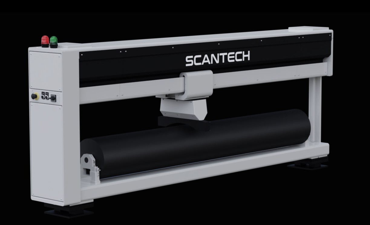
A scanner turns individual measurements into a cross-direction profile and a machine-direction trend. That data can reveal thick lanes, edge effects, periodic drift, coating streaks, and startup behavior, then feed alarms, reports, or automatic correction.
Which web gauging technology should you evaluate first?
This selector provides a practical starting direction. It is not a substitute for sample testing, range review, scanner layout, calibration work, safety review, or final factory confirmation.
Read the profile before changing the process
A scanner produces two different kinds of information. The cross-direction profile shows variation across the web width. The machine-direction trend shows how the average or selected zones change over time. The pattern often tells you where to investigate first.
The main web gauging technologies
Each technology converts a different physical interaction into a process measurement. The best choice is the one whose signal remains most closely tied to your true quality characteristic as material, color, temperature, density, passline, and line conditions change.
Measures attenuation through the web. Strong for basis weight and calibrated thickness across many films, sheets, coatings, foams, filled products, energy materials, and multilayer webs. It is non-radioactive and supports scanning profiles and closed-loop control.
A mature attenuation method using a sealed radioactive isotope. It has been widely used for basis weight and thickness, but source decay, licensing, leak testing, handling, and end-of-life disposal are part of ownership.
A single-sided nuclear method that measures radiation scattered back from the product. It can serve thick or dense applications where transmission geometry is impractical, but standoff, product position, response speed, and regulatory obligations matter.
Uses wavelength-specific absorption to infer moisture, solvent, coat weight, polymer chemistry, or selected layers. It can be very selective, but calibration is product-specific and may be affected by color, surface, temperature, scattering, and formulation changes.
Triangulation, shadow, confocal, and related optical methods measure surface position, width, edge, or physical thickness. They do not directly measure mass per area. Surface reflectivity, transparency, roughness, flutter, angle, and passline can influence the result.
Uses acoustic time, attenuation, or resonance through a material. It can be useful on selected foams, composites, and structured products, but acoustic coupling, air gap, material velocity, temperature, porosity, and attenuation require application-specific validation.
Combines complementary measurements or multiple scanner stations. X-ray plus laser can calculate density. Pre- and post-coating stations can isolate coating add-on. Infrared can add chemistry or moisture. Vision can add defect inspection.
How the technologies differ
This table is intentionally practical. It describes the typical measurement relationship, not an absolute promise for every material or installation.
| Technology | Primary signal | Usually strongest for | Important sensitivities | Ownership / installation |
|---|---|---|---|---|
| Low-energy X-ray | Photon attenuation through the web | Basis weight, calibrated thickness, coating add-on, filled and multilayer products, control profiles | Composition, density model, calibration sample quality, air gap and geometry | Non-radioactive; two-sided transmission geometry is typical |
| Beta transmission | Beta attenuation | Basis weight and calibrated thickness on established applications | Composition, source decay, window contamination, passline and calibration | Sealed isotope; licensing, radiation-safety program, leak tests and disposal |
| Gamma backscatter | Backscattered gamma radiation | Thick or dense webs with single-sided access | Standoff, web position, density/composition, response speed | Sealed isotope and single-sided installation; regulatory program required |
| IR / NIR | Wavelength-specific absorption and reflection | Moisture, solvent, coat weight, chemistry, selected layers | Color, gloss, temperature, scattering, formulation, optical path | Non-radioactive; product-specific calibration is central |
| Laser / optical | Surface position, shadow, displacement or optical focus | Physical thickness, width, edge, surface profile, geometry | Flutter, transparency, reflectivity, roughness, angle, passline | Non-radioactive; may require two opposing heads or a reference roll |
| Ultrasonic | Acoustic travel time, attenuation or resonance | Selected foam, composite, layered or structured materials | Sound velocity, temperature, coupling, air gap, porosity and attenuation | Non-radioactive; application validation is essential |
| Multi-sensor | Two or more complementary signals | Density, porosity, coating deduction, layer information, defect + gauge | Time/position registration, calibration model, sensor synchronization | Higher integration effort, but often the only way to separate variables |
Web gauging application matrix
Search by material, process, measurand, or technology. The recommended technology is a starting point, not a final specification.
| Application | Primary measurand | Starting technology | What needs special attention | Gauge Advisor resource |
|---|---|---|---|---|
| Blown film at the layflat | Film thickness and polar profile from a double layer | Low-energy X-ray with layflat algorithms[3] | Double-layer deconvolution, bubble rotation, die/air-ring mapping, filler and barrier layers | Blown-film X-ray guide |
| Cast film and sheet | Thickness, basis weight, density, defects, CD profile | X-ray; add laser when true caliper or density is needed | Fillers, multilayer structure, web flutter, die-bolt mapping and scan speed | Film & sheet solutions |
| Biaxial and MDO film | Thickness, density, porosity, stretch profile | X-ray or multi-sensor X-ray + laser | Stretch-zone registration, edge profile, fillers, multiple control sections | X-ray web gauging guide |
| Extrusion coating | Coating add-on or coating thickness | Pre/post X-ray with same-spot differential deduction | Substrate variability, line delay, edge trim, draw, station registration | Coating-gauge ROI guide |
| Foam sheet and foam web | Thickness, basis weight, density and porosity | X-ray plus laser/optical caliper | Surface texture, compressibility, cell structure, temperature and web support | Film & sheet measurement |
| Paper and board | Grammage, moisture, caliper and profile | X-ray or existing beta; add moisture and caliper sensors as needed | Moisture compensation, basis-weight convention, ash/filler and grade changes | X-ray web gauging guide |
| Nonwovens and technical textiles | Basis weight, density, uniformity and defects | X-ray; multi-sensor for thickness/density | Open structure, loft, air movement, fiber composition and web flutter | Coating & web solutions |
| Adhesive and functional coating | Coat weight, thickness, moisture or solvent | X-ray differential; IR/NIR when chemistry provides a strong signal | Wet versus dry state, substrate variation, cure, solids and formulation changes | Coating measurement pillar |
| Battery electrode coating | Coating weight, thickness, density and side-to-side balance | Application-specific X-ray, often combined with laser | Metal foil, high-Z active material, double-sided layers, edge regions and calibration set | Battery measurement solutions |
| Fuel-cell and CCM production | Catalyst loading, coating uniformity and layer properties | Application-specific X-ray or multi-sensor approach | Platinum-group elements, membrane substrate, low add-on, side differentiation | Fuel-cell measurement |
| Prepreg and composites | Fiber/resin basis weight, add-on and uniformity | Low-energy X-ray or application-specific multi-sensor system | Fiber type, weave, resin chemistry, backing paper and impregnation state | Prepreg measurement solutions |
| Lamination and converting | Total basis weight, layer add-on, thickness and defects | X-ray, IR, optical or multi-station differential | Multiple substrates, adhesive, trapped air, web registration and station timing | Coating systems overview |
| Multilayer and barrier film | Total thickness plus selected layer or composition information | X-ray for total; IR/NIR or model-based multi-sensor for layer information | Layer chemistry, density, tie layers, formulation changes and calibration samples | X-ray technology guide |
| Filled or recycled film and sheet | Thickness, basis weight and density | X-ray plus laser when composition or density varies | PCR variability, mineral loading, pigment, density shifts and grade-specific calibration | Extrusion troubleshooting |
| Coated metal and foil | Metal thickness or coating weight | Application-specific X-ray measurement | Alloy, substrate thickness, coating chemistry, energy range and safety enclosure | Coating measurement systems |
| Very wide or high-speed web | Fast, repeatable full-width profile | Technology depends on material; scanner architecture becomes equally important | Frame stiffness, scan speed, profile time, footprint, environment, access and maintenance | Web gauging ROI calculator |
How each technology works, and where the traps are
Open any section for a deeper technical explanation. The goal is not to declare one sensor universally “best,” but to show what each one is actually measuring.
1Low-energy X-ray transmissionThe broadest modern platform for basis weight, calibrated thickness, coating and multi-property web measurement
An X-ray source sits on one side of the web and a detector sits on the other. The system measures how much photon intensity is attenuated by the material. NIST publishes mass attenuation data for elements, compounds, and mixtures, illustrating why photon response depends on both energy and material composition.[4]
Why processors choose it
- Non-contact and non-radioactive
- Strong response on lightweight films, coatings, foams, energy materials and filled webs
- Works across transparent, opaque, glossy and colored products
- Supports cross-direction profiles, roll reports, alarms and automatic control
- Can be combined with laser, infrared, microwave or vision sensors
What must be reviewed
- Whether the required output is basis weight or inferred thickness
- Density, filler, pigment, recycled content and layer changes
- Maximum attenuation range and product structure
- Air gap, scanner width, edge transitions and passline
- Calibration sample quality and accepted laboratory reference
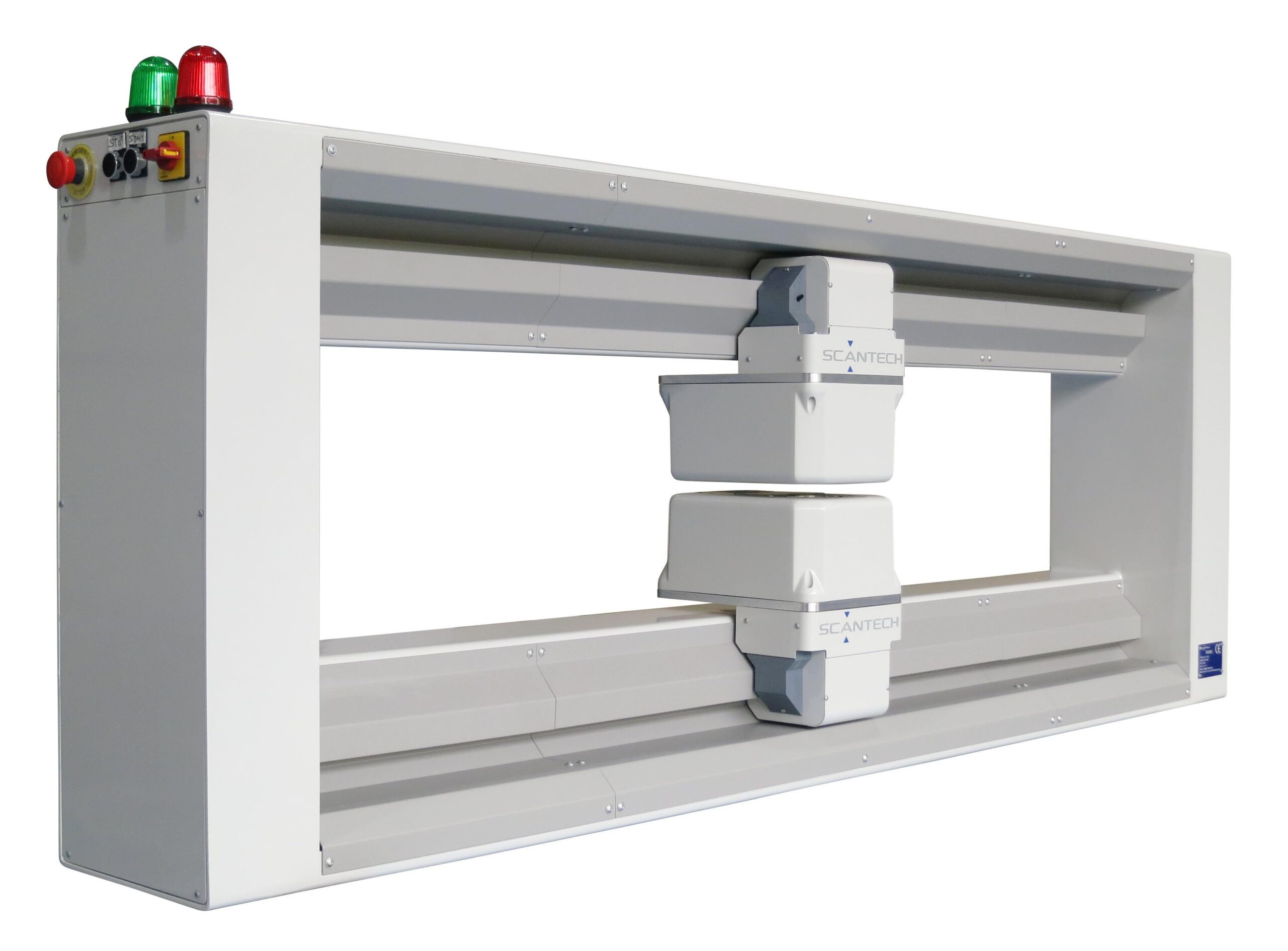
Scantech’s extrusion literature describes low-energy X-ray systems for biax film, blown film, cast film, MDO film, extrusion coating and foam, with combinations of thickness, basis weight, density, porosity, filler, barrier-layer and defect information depending on the application.[1]
2Beta transmissionA proven attenuation method with an added radioactive-source ownership burden
Beta gauges also place a source and detector on opposite sides of the product. The measured signal is related to attenuation through the web, making beta useful for basis weight and calibrated thickness. Many plants still operate reliable legacy systems.
Technical strengths
- Long industrial history and well-understood applications
- Useful mass-per-area sensitivity in established ranges
- Can provide continuous profile data when mounted on a scanner
- May be practical when maintaining an existing licensed system
Ownership considerations
- Radioactive-material licensing or registration requirements
- Radiation-safety procedures, training and inspections
- Leak testing and source accountability
- Source decay and calibration drift over time
- Shipping, relocation, transfer and end-of-life disposal
U.S. NRC guidance for fixed gauges addresses licensing, radiation safety, sealed-source accountability and program responsibilities.[7] A replacement decision should compare measurement performance and lifecycle burden, not only the initial equipment price.
3Gamma backscatterSingle-sided access for specialized thick or dense products, with nuclear-gauge requirements
Backscatter systems place the source and detector on the same side and interpret radiation returning from the product. This can be useful when the web is too thick, too dense, or physically inaccessible for a transmission beam.
Where it can fit
- Thick sheet, board, rubber, carpet or dense web products
- Single-sided installations where no lower head can be mounted
- Existing processes built around a validated backscatter method
Why it needs caution
- Standoff and passline movement can affect the signal
- Response may be slower or less sensitive on lightweight webs
- Density and composition remain part of the calibration
- The sealed source creates the same broad regulatory responsibilities as other nuclear gauges
The IAEA classifies transmission and backscatter nuclear gauges by measurement geometry and provides global guidance covering shielding, source accountability, maintenance, transport, storage, and disposal.[8]
4Infrared and near-infraredPowerful when the target constituent has a distinct optical signature
Infrared systems illuminate the web at selected wavelengths and analyze absorption or reflection. The signal may correlate to moisture, solvent, coat weight, polymer chemistry or a layer that absorbs differently from the substrate.
Strong applications
- Moisture or solvent monitoring
- Organic coatings with a useful absorption band
- Barrier or adhesive layers that differ chemically from the base
- Situations where single-sided optical access is attractive
Calibration risks
- Color, gloss, surface roughness and scattering
- Web temperature and optical path changes
- Formulation, pigment, additive and cure-state changes
- Overlapping absorption from substrate and coating
- Trying to use one calibration across materially different products
Infrared can be exceptionally useful when the chemistry is favorable, but it is not a universal geometric thickness gauge. Representative samples should cover the real production range, including expected formulation and surface changes. Published NIR work on thin printed layers likewise shows that useful in-line coating-weight predictions depend on application-specific calibration and control of substrate or surface effects.[11]
5Laser and optical geometryDirect physical thickness, surface position and edge information without measuring mass
Optical methods include triangulation, shadow measurement, confocal sensing and related displacement techniques. A tutorial review in Advances in Optics and Photonics covers triangulation, confocal, interferometric and other non-contact distance methods.[9]
Where optics are strong
- Direct physical caliper or surface displacement
- Width, edge, deckle and profile geometry
- Thick, porous or low-density products where mass and thickness must be separated
- Density calculation when paired with an X-ray basis-weight signal
- Visual or geometric defect inspection
Where optics can struggle
- Transparent, translucent, glossy or mirror-like surfaces
- Rough texture, embossing, fiber loft or specular reflections
- Web flutter, angle and passline movement
- One-sided measurements without a stable reference surface
- Confusing surface height with total thickness
Scantech’s portfolio combines X-ray, laser and visual-inspection options on certain extrusion and web applications, allowing the measurement architecture to be matched to the process rather than forcing one sensor to provide every result.[1]
6Ultrasonic transmissionA specialized acoustic option whose performance depends strongly on the material and air path
Ultrasonic systems transmit acoustic energy through or into the web and use time-of-flight, attenuation, resonance or phase behavior. The method can be useful for selected composites, foam, layered products and non-destructive evaluation tasks.
Potential advantages
- Non-ionizing and non-contact in air-coupled configurations
- Can respond to internal structure, bonding or porosity
- Useful where optical contrast is poor
- Can complement another thickness or mass measurement
Application variables
- Acoustic velocity changes with composition, structure and temperature
- Air gaps and transducer alignment affect signal strength
- Highly attenuating or open structures may reduce transmission
- Line noise, flutter and surface geometry can complicate interpretation
- Calibration may not transfer cleanly across grades
For general web-gauging selection, ultrasonic measurement should be treated as an application-specific option rather than assumed to be composition-independent. Air-coupled resonance research demonstrates that thickness and sound velocity can be determined together, but only through a material-specific acoustic model and suitable signal quality.[12]
7Multi-sensor, same-spot and differential measurementSeparate variables that one sensor cannot distinguish on its own
A multi-sensor architecture can combine two properties at one scanner or compare two scanner stations along the line. This is often the strongest answer when the process needs more than total attenuation.
Common combinations
- X-ray + laser: basis weight plus physical thickness for density or porosity
- Pre-coat + post-coat X-ray: substrate and total web for coating add-on
- X-ray + IR: total mass plus selected composition or moisture
- Gauge + visual inspection: dimensional profile plus defects
- Multiple control stations: profile tracking before and after stretch, coating, drying or lamination
Integration details that matter
- Matching the same material location after transport delay
- Accounting for stretch, neck-in, edge trim and web wander
- Synchronizing scanner position, line speed and encoder data
- Using calibration samples that span both variables
- Deciding which result drives the control loop
Scantech identifies same-spot and differential-deduction approaches for extrusion coating, along with coating thickness, defect detection and automatic control options.[2]
Estimate coating add-on and equivalent dry thickness
This simplified calculator illustrates differential deduction. It assumes the pre-coat and post-coat values represent the same web location and that the entered coating density is valid.
A good sensor can still produce bad process information
Measurement technology is only one part of the project. Scanner mechanics, line conditions, calibration, data timing and the correction device determine whether the system becomes a trusted production tool.
Place the scanner where the product is stable and where the result still arrives in time to support correction.
Review tension, guiding, flutter, passline, roll wrap, edge movement and scanner access.
Use representative samples and an accepted lab method across the real operating range.
Align scanner position to die bolts, air-ring zones, coat-head actuators, stretch zones or MD controls.
Confirm direction, gain, response time, limits, alarms and what happens during grade changes or web breaks.
The frame must cover the full usable web and hold sensor geometry under acceleration, vibration and thermal change.
A fast line does not automatically require the fastest scanner, but the complete profile must update quickly enough for the process dynamics.
Small defects, narrow coating lanes and sharp edges can be averaged by a large measurement footprint.
Flutter, wrinkles and lateral movement can distort optical geometry, edge mapping, differential registration and control-zone alignment.
Heat, dust, fumes, solvent, static, condensation, vibration, washdown and hazardous-area requirements affect the frame, windows and electronics.
Use the actual materials, layer structures, fillers, pigments, densities and laboratory references expected in production.
Define recipes, analog or digital communications, roll reports, alarms, historian data, quality limits and operator access.
A gauge cannot correct a profile unless the line has a usable actuator, proper mapping and enough response range to influence the defect.
Monitoring, machine-direction control, and cross-direction control are different projects
Many systems begin with measurement and reporting. Automatic control adds more value when the measurement is stable, the actuator is understood, and the line response has been validated.
Profiles, trends, roll reports, alarms and recipe comparisons help operators see drift earlier, verify product, and identify whether a problem is localized or line-wide.
- No automatic process correction required
- Good first step for legacy lines
- Useful for quality documentation and ROI baseline
The system regulates an overall process variable such as extruder output, line speed, coating flow, gap, pump speed or another actuator to maintain the average target over time.
- Focuses on the web average or selected zone
- Requires a stable process response and delay model
- Cannot remove a persistent cross-web shape by itself
The measured profile is mapped to multiple physical zones such as die bolts, thermal actuators, air-ring zones, coat-head actuators or stretch controls.
- Mapping and web registration are critical
- Correction resolution must match the profile defect
- Automatic control should include limits and safe fallback behavior
Scantech’s extrusion materials describe machine-direction control, automatic profile control, die-bolt control, automatic mapping and related control functions across multiple film and coating processes.[1] Academic reviews of sheet and film control similarly separate MD control from the more spatially complex CD profile-control problem and emphasize sensing delay, actuator interactions, mapping, and constraints.[10] On lines where web tension or lateral position is part of the problem, use the Web Tension & Guiding Equipment Selector to review the downstream handling architecture separately.
Related Gauge Advisor tools and technical resources
Use the application-specific page when you already know the process, or start with a calculator when you are building the financial case.
Web gauging FAQ
What is a web gauging system?
A web gauging system measures one or more properties of a continuously moving sheet, film, coating, paper, nonwoven, foil, composite or other roll-to-roll product. A scanning frame moves the sensor across the width to build a cross-direction profile while software tracks machine-direction trends, alarms, reports and control outputs.
Does an X-ray gauge measure thickness or basis weight?
The primary physical interaction is photon attenuation through the material. In many lightweight web applications that signal is closely related to mass per unit area. The system can report calibrated thickness when density and composition are sufficiently known. When density changes independently, combining X-ray with a geometric thickness sensor provides a clearer separation.
Why would a plant replace a beta gauge with X-ray?
Common reasons include removing a sealed radioactive source, avoiding source decay, simplifying relocation and disposal, improving measurement performance on lightweight or complex materials, and adding modern controls or multi-sensor capability. The existing product range and correlation requirements should still be tested before replacement.
Can one web gauge measure coating thickness?
Sometimes. If the substrate is stable and the coating produces enough independent signal, a single station may work. When substrate variation is significant, a pre-coat and post-coat differential system can subtract the registered substrate contribution. Chemistry-specific IR or a multi-sensor design may be better for certain layers.
How is web density calculated?
Density is generally derived from basis weight divided by physical thickness, with consistent units. This is why foam, porous film, paper, nonwoven and battery-electrode applications often combine a mass-sensitive sensor with a laser or optical caliper measurement.
Does color affect X-ray measurement?
Visible color itself is not the measurement mechanism, but the pigment or filler that creates the color may change elemental composition and attenuation. Carbon black, titanium dioxide, calcium carbonate, barium sulfate and other additives should be represented in the calibration plan.
Can the gauge automatically control a die or coating process?
Yes, when the measurement is stable and the line has an appropriate actuator. Machine-direction control adjusts an overall process variable. Cross-direction control maps profile zones to multiple die, air-ring, coating-head or stretch actuators. The mapping, delay, correction authority and safe operating limits must be reviewed.
How should an online gauge be correlated to the lab?
Agree on the reference method, sampling location, conditioning, specimen size, units and timing. Use samples that span the operating range and expected material variations. The goal is not to make unlike methods numerically identical by force, but to establish a stable, documented relationship suitable for production decisions.
What information is needed for a web gauge quotation?
Provide the material and layer structure, target measurand, minimum and maximum thickness or basis weight, web width, line speed, passline, current lab method, expected composition changes, environment, available scanner space, required control outputs, PLC/communications and any regulatory or hazardous-area requirements.
Sources used in this guide
The outside references below are limited to Scantech, standards organizations, government resources and neutral technical literature. Competitive web-gauge suppliers are intentionally excluded.
- Scantech. Extrusion Industry: Online Measurement and Control. Applications, measurements, scanner ranges and control functions for biax, blown, cast, foam, MDO and extrusion-coating lines.
- Scantech. Coating Films Measurement. Coating thickness, defect detection, differential deduction, same-spot and control functions.
- Scantech. Blown Film Measurements. Layflat X-ray measurement, double-layer deconvolution, mapping and control.
- National Institute of Standards and Technology. X-Ray Mass Attenuation Coefficients. Photon mass attenuation data for elements, compounds and mixtures.
- ASTM International. ASTM D6988-21, Standard Guide for Determination of Thickness of Plastic Film Test Specimens.
- TAPPI. TAPPI/ANSI T 410 om-23, Grammage of Paper and Paperboard.
- U.S. Nuclear Regulatory Commission. NUREG-1556, Volume 4: Consolidated Guidance About Materials Licenses, Program-Specific Guidance About Fixed Gauge Licenses.
- International Atomic Energy Agency. Radiation Safety in the Use of Nuclear Gauges, IAEA Safety Standards Series No. SSG-58. Global safety guidance for transmission, backscatter and other industrial nuclear gauges.
- Berkovic, G. and Shafir, E. Optical Methods for Distance and Displacement Measurements, Advances in Optics and Photonics, 2012.
- VanAntwerp, J. G., Featherstone, A. P., Braatz, R. D., and Ogunnaike, B. A. Cross-Directional Control of Sheet and Film Processes, Automatica, 2007. Review of MD/CD estimation, scanning measurements, process delay, actuator interactions and control constraints.
- Mirschel, G., Heymann, K., Savchuk, O., Genest, B., and Scherzer, T. In-Line Monitoring of the Thickness of Printed Layers by Near-Infrared Reflection Spectroscopy, Applied Spectroscopy, 2012. Demonstrates NIR coating-weight measurement and the importance of calibration and surface/substrate effects.
- Gómez Álvarez-Arenas, T. E. Simultaneous Determination of Ultrasound Velocity and Thickness of Solid Plates Using Air-Coupled Ultrasound, Ultrasonics, 2010. Demonstrates resonance-based non-contact thickness and acoustic-property determination.
Need a Scantech web gauging recommendation, quote, or application review?
Gauge Advisor is the authorized Scantech sales and applications support representative for web gauging and control systems. I help manufacturers select, quote, integrate, and support Scantech systems for film, sheet, extrusion coating, adhesive coating, battery electrodes, fuel-cell materials, prepreg, nonwovens, paper, laminating and other continuous web processes.
This application review is provided in connection with Scantech equipment. Gauge Advisor is an equipment sales and applications support firm, not a standalone process consulting service. Send the details below and I will respond within one business day, often within a few hours.
- Material and layer structure
- Thickness, basis-weight or coating range
- Web width and line speed
- Current laboratory reference method
- Fillers, pigments, recycled content or composition changes
- Available scanner space and passline
- Monitoring, reporting or closed-loop control goal
- PLC, communication and environmental requirements