Updated October 10, 2026
When an extrusion line starts making bad product, the visible defect is not always the root cause. I have seen processors chase a die setting when the real problem was inconsistent feeding, cooling, puller speed, internal air pressure, or a downstream web-handling issue.
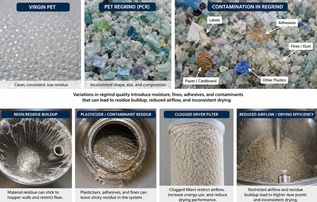
This plastics extrusion troubleshooting guide organizes 26 common problems across blown film, cast film, sheet, tubing, pipe, and profile extrusion. Use the matrix to narrow the search, then open the detailed sections for the checks I would make before changing several settings at once.
Connected process path: Once the symptom is isolated, follow the connected process path from resin preparation and feeding through melt-pressure control and finished-product quality.
Related next steps: desiccant resin drying systems, continuous gravimetric blenders, central resin conveying systems, resin dust collection and air filtration, and extrusion pressure stability.
A four-step extrusion troubleshooting method
A disciplined process prevents one problem from becoming three. These four checks apply to nearly every extrusion defect.
Record what changed, where it appears, when it started, and whether it is continuous, periodic, or random.
Confirm material, recipe, moisture, instruments, setpoints, actual speeds, output, and recent maintenance or changeover activity.
Trend pressure, temperature, motor load, feeder rate, line speed, dimensions, cooling, vacuum, and tension on one time scale.
Use a controlled test, allow the process to respond, save the result, and avoid simultaneous adjustments that hide cause and effect.
Where extrusion problems can originate
The finished product is the result of a connected system. Trace the defect upstream and downstream instead of assuming the extruder or die is always responsible.
Do not troubleshoot every polymer the same way
The same symptom can point to a different cause depending on the material. Before adjusting the line, confirm the exact resin grade, melt-flow range, additive package, regrind level, drying requirement, and recent lot or supplier change.
Common in blown and cast film. Watch melt strength, drawdown, bubble cooling, frost-line stability, gauge bands, blocking, and additive distribution. A change in blend ratio or slip/antiblock package can alter both processing and winding.
Used in film, pipe, sheet, and profiles. Its higher crystallinity makes cooling history, shrinkage, orientation, and dimensional stability especially important. In blown film, processing behavior can differ sharply from LDPE-rich structures.
Common in cast film, sheet, pipe, and profiles. Pay close attention to cooling symmetry, crystallization, warpage, draw conditions, and thermal shrinkage. Copolymer and homopolymer grades can respond differently.
Used in sheet, film, and some tubing. Moisture control is critical because hydrolysis can reduce molecular weight before obvious bubbles appear. Verify moisture at the throat, not only dryer setpoints.
Common in medical and industrial tubing, film, and profiles. Both can be moisture-sensitive, while soft or tacky grades may create feeding, conveying, calibration, or puller challenges. Cooling and internal air support can strongly affect tubing geometry.
Used heavily in pipe, profile, sheet, and tubing. Thermal history, shear, fusion, stabilizer condition, and residence time matter. Treat discoloration, odor, or plate-out as a process-history problem, not simply a temperature-setting problem.
Moisture, contamination, thermal degradation, polishing condition, and cooling stress can show up as haze, streaks, bubbles, or optical distortion. A surface that looks acceptable under normal light may still fail optical inspection.
Expect wider variation in contamination, moisture, bulk density, viscosity, color, and thermal history. Trend incoming material properties and screen-loading rate instead of assuming the extruder can absorb every change.
In coextruded film, sheet, or tubing, a defect may originate in one layer even when it appears across the complete structure. Compare layer ratios, individual extruder pressures, temperatures, feed rates, and interfacial stability.
Machine direction, cross direction, or random?
This distinction is one of the fastest ways to reduce the list of possible causes.
The defect changes over time along the running direction. Check feeding, pressure, screw and drive cycles, take-up speed, pullers, temperature control, and draw resonance.
The same lane or circumferential position remains high, low, thick, thin, hot, or loose. Check die flow, air distribution, roll condition, cooling, tooling alignment, and profile mapping.
Intermittent events often point toward contamination, moisture, degradation, handling damage, a loose component, or a defect that only occurs during a cycle or changeover.
Extrusion troubleshooting matrix: 26 common problems
Search by symptom or filter by process. Each row includes the first checks I would make before changing multiple settings.
| Problem & processes | Likely causes | What to check first | Gauge Advisor resource |
|---|---|---|---|
| 1Inconsistent material feed or hopper bridging Blown FilmCast FilmSheetTubingPipeProfile View detailed checks |
Bridging, rat-holing, changing bulk density, poor throat cooling, conveying interruptions, feeder calibration, or stringers in the material stream. | Watch hopper level, feeder output, screw amperage, head pressure, and actual pounds per hour at the same time. | Resin Handling Equipment Selector |
| 2Moisture, bubbles, voids, or splay Blown FilmCast FilmSheetTubingPipeProfile View detailed checks |
Insufficient drying, wet regrind, moisture pickup after drying, trapped air, volatiles, leaks, or excessive residence time. | Measure moisture at the machine throat, then verify dryer temperature, dew point, airflow, residence time, and material return path. | Resin Conveying & Blending Solutions |
| 3Blend, color, or additive variation Blown FilmCast FilmSheetTubingPipeProfile View detailed checks |
Feeder error, ingredient segregation, refill cycles, changing regrind, poor mixing, recipe mistakes, or inconsistent material inventory. | Compare commanded and actual ingredient rates, collect timed samples at the throat, and look for variation tied to feeder refill or receiver cycles. | Resin Handling Equipment Selector |
| 4Gels, black specks, or contamination Blown FilmCast FilmSheetTubingPipeProfile View detailed checks |
Contaminated resin or reclaim, degraded polymer, dead spots, poor shutdowns, dirty conveying, inadequate filtration, or excessive residence time. | Separate incoming contamination from in-process degradation by inspecting purge, screen debris, startup timing, and the full material path. | Filtration & Screen Changer Selector |
| 5Melt pressure fluctuations or output surging Blown FilmCast FilmSheetTubingPipeProfile View detailed checks |
Unstable feed, screw or barrel wear, heater cycling, screen loading, drive variation, poor control tuning, or an unstable downstream restriction. | Trend inlet and head pressure with screw speed, motor load, temperatures, feeder rate, output, and take-up speed. | Extrusion Pressure Fluctuations Guide |
| 6Steadily rising head pressure or frequent screen changes Blown FilmCast FilmSheetTubingPipeProfile View detailed checks |
High contaminant loading, excessive screen fineness, low melt temperature, degradation, small flow area, or a restricted screen changer. | Measure pressure before and after filtration, inspect captured material, and compare pressure-rise rate with resin, regrind, output, and temperature. | Filtration & Screen Changer Selector |
| 7Low output or excessive motor load Blown FilmCast FilmSheetTubingPipeProfile View detailed checks |
Feed limitation, high restriction, cold or high-viscosity melt, screw wear, poor screw design, excessive backpressure, or downstream speed limits. | Measure actual mass output and compare it with screw speed, motor load, head pressure, melt temperature, and historical performance. | Extrusion Throughput & Line Speed Calculator |
| 8Excessive melt temperature, odor, or polymer degradation Blown FilmCast FilmSheetTubingPipeProfile View detailed checks |
Shear heating, excessive backpressure, long residence time, heater faults, dead spots, poor shutdowns, oxygen exposure, or an unsuitable process window. | Verify true melt temperature independently, then review residence time, pressure, motor load, purge appearance, and hot-zone control. | Extrusion Pressure Fluctuations Guide |
| 9Unmelted resin or poor melt homogeneity Blown FilmCast FilmSheetTubingPipeProfile View detailed checks |
Insufficient melting length or energy, excessive rate, unsuitable screw, damaged screw, poor mixing, low feed temperature, or mixed pellet characteristics. | Inspect purge and screen debris, compare output per rpm with melt temperature uniformity, and look for unmelt tied to rate or material changes. | Polymer Filtration & Melt Pumps |
| 10Melt fracture or sharkskin Blown FilmCast FilmSheetTubingPipeProfile View detailed checks |
Excessive shear stress at the die exit, high output for the die gap, low melt temperature, resin rheology, damaged lands, or poor die geometry. | Find the output or line-speed threshold where roughness begins, then compare die pressure, melt temperature, resin lot, gap, and lip condition. | Extrusion Throughput & Line Speed Calculator |
| 11Die lines, streaks, or drag marks Blown FilmCast FilmSheetTubingPipeProfile View detailed checks |
Die-lip damage, carbon buildup, contamination, poor cleaning, thermal imbalance, welds, or a restricted flow passage. | Mark the defect location, inspect whether it stays fixed relative to the die, then clean and examine the lip and land under safe conditions. | Filtration & Screen Changer Selector |
| 12Surface scratches, pits, lumps, or dents Cast FilmSheetTubingPipeProfile View detailed checks |
Contact with guides or rolls, die contamination, cooling-tank debris, handling damage, lumps or neckdowns, air bubbles, or embedded foreign material. | Inspect the product at successive points from the die to the take-up to find exactly where the defect first appears. | Tubing Surface Defect Guide |
| 13Cross-direction thickness variation or gauge bands Blown FilmCast FilmSheet View detailed checks |
Die profile, air-ring or cooling imbalance, blocked airflow, roll-temperature variation, die alignment, manifold distribution, or localized buildup. | Use a cross-web profile to identify persistent thick and thin positions, then compare them with die, air, cooling, and roll locations. | How to Reduce Blown Film Gauge Variation |
| 14Machine-direction gauge or dimensional variation Blown FilmCast FilmSheetTubingPipeProfile View detailed checks |
Output surging, feeder pulses, screw or drive variation, temperature cycling, take-up speed variation, pump-control interaction, or draw resonance. | Measure the period of the variation and match it against feeder, screw, heater, pump, roll, puller, and line-speed cycles. | Extrusion Pressure Fluctuations Guide |
| 15Uneven wall thickness or poor concentricity TubingPipeProfile View detailed checks |
Tooling misalignment, off-center mandrel, uneven melt flow, temperature imbalance, vacuum or sizing issues, puller alignment, or inadequate multi-axis measurement. | Measure OD, ID, and wall around the full circumference, then compare the result before and after cooling and puller contact. | Tubing Diameter & Wall Thickness Guide |
| 16Diameter, width, or profile drift Blown FilmCast FilmSheetTubingPipeProfile View detailed checks |
Output-to-line-speed mismatch, thermal warm-up, die swell, resin viscosity changes, vacuum drift, cooling changes, puller slip, or encoder error. | Trend dimension against actual mass output, line speed, melt temperature, vacuum, cooling temperature, and elapsed time from startup. | Extrusion Throughput & Line Speed Calculator |
| 17Edge bead or excessive neck-in Cast FilmSheet View detailed checks |
High draw ratio, large die-to-nip distance, melt elasticity, edge cooling, die deckling, edge pinning, nonuniform flow, or line-speed changes. | Measure edge thickness and final width while changing only one variable, then compare the response with draw ratio, air gap, melt temperature, and edge-control settings. | Film & Sheet Thickness Measurement |
| 18Blown-film bubble instability or a moving frost line Blown Film View detailed checks |
Uneven or insufficient cooling, air-ring or IBC problems, drafts, output fluctuation, unsuitable BUR or drawdown, cage contact, or collapsing-frame issues. | Watch bubble shape and frost-line height through a full cycle while trending output, pressure, cooling air, IBC, nip speed, and ambient drafts. | Blown Film Air Ring Selector |
| 19Sheet warpage, curl, or uneven cooling Cast FilmSheetProfile View detailed checks |
Asymmetric cooling, uneven thickness, roll-temperature imbalance, roll deflection or alignment, residual orientation, poor support, or excessive cooling rate. | Record which direction the product curls, compare top and bottom temperatures, and map thickness, roll conditions, and cooling symmetry. | Film & Sheet Thickness Measurement |
| 20Tubing or pipe ovality TubingPipe View detailed checks |
Insufficient cooling or support, vacuum-sizing problems, belt compression, uneven wall, gravity sag, misalignment, or hot handling. | Measure OD on multiple axes at several positions along the line, then compare product temperature, vacuum, support, and puller contact. | Tubing Diameter & Wall Thickness Guide |
| 21Unstable tubing internal air pressure or support TubingPipe View detailed checks |
Regulator variation, leaking lines or fittings, restricted airflow, poor tube sealing, pressure measurement too far from the die, or control interaction with output and line speed. | Trend internal air pressure with OD, line speed, melt pressure, and output. Check the regulator, restriction, connections, leaks, and where pressure is measured. | Tubing Measurement Selector |
| 22Profile sag, twist, or shape distortion Profile View detailed checks |
Uneven flow or wall, asymmetric cooling, insufficient support, die swell, gravity, puller misalignment, residual stress, or speed changes. | Compare the hot shape at die exit with the shape after each cooling and support stage to find where distortion begins. | Cooling Tank Length Calculator |
| 23Draw resonance or periodic thickness oscillation Cast FilmSheetTubingProfile View detailed checks |
Unstable draw ratio, excessive unsupported draw, viscoelastic instability, take-up oscillation, control-loop interaction, or output variation. | Calculate the oscillation period and wavelength, then compare them with line speed, draw ratio, air gap, drive signals, and pressure trends. | Extrusion Throughput & Line Speed Calculator |
| 24Wrinkles, baggy lanes, or uneven web tension Blown FilmCast FilmSheet View detailed checks |
Cross-web gauge variation, roll or frame misalignment, uneven tension, entrained air, thermal shrinkage, excessive drag, or collapsing-frame setup. | Determine whether wrinkles follow thick or thin lanes, begin at a specific roll, change with tension, or originate during bubble collapse. | Web Tension & Guiding Equipment Selector |
| 25Web wandering or poor edge alignment Blown FilmCast FilmSheet View detailed checks |
Roll misalignment, uneven tension or profile, poor guide geometry, sensor contamination, actuator limits, splice effects, or bubble instability. | Trace the edge position through each span and record where movement begins relative to guides, rolls, tension zones, and thickness profile. | Web Tension & Guiding Equipment Selector |
| 26Poor roll build, telescoping, starring, or blocking Blown FilmCast FilmSheet View detailed checks |
Incorrect winding tension or taper, gauge bands, entrained air, core or chuck problems, hot film, slip or antiblock issues, or poor alignment. | Map roll hardness, temperature, gauge profile, tension, core alignment, and defect location from the first wraps to full diameter. | How to Reduce Blown Film Gauge Variation |
Causes, checks, and corrective direction
Open any problem below for a more complete troubleshooting path. I have kept the checks practical, but the right correction still depends on the resin, machine, tooling, product geometry, and approved plant procedure.
Material handling and feed
Start at the resin source. It is easy to blame the screw or die, but a surprising number of extrusion problems begin in storage, drying, conveying, blending, or feeding.
1 Inconsistent material feed or hopper bridgingBlown FilmCast FilmSheetTubingPipeProfile
What it looks like: Output, pressure, dimensions, or color drift even though screw speed and operator setpoints appear steady. The problem may come and go as material collapses into the throat or as a receiver cycles.
Likely causes
- Pellets or regrind bridging above the feed throat, especially with irregular regrind, soft materials, or poor hopper geometry.
- Intermittent conveying, receiver discharge, line plugging, angel hair, or a material-routing problem upstream.
- Changing bulk density or regrind percentage that changes how much mass enters per screw revolution.
- An overheated or poorly cooled feed throat that allows pellets to soften and restrict flow.
- Loss-in-weight or additive feeder calibration, refill, vibration, or recipe issues.
What to check first
- Confirm that material is physically flowing into the throat while the symptom occurs. Do not rely only on a high-level switch.
- Trend feeder rate, screw speed, motor load, head pressure, and finished dimensions on the same time scale.
- Check receivers, filters, vacuum level, conveying line routing, and the condition of regrind or stringers.
- Compare actual mass throughput with the expected output from the screw speed.
2 Moisture, bubbles, voids, or splayBlown FilmCast FilmSheetTubingPipeProfile
What it looks like: Bubbles or voids appear in the wall, silver streaks or splay appear on a surface, the melt spits at the die, or dimensions become noisy. Hygroscopic resins may also lose molecular weight or properties without an obvious bubble.
Likely causes
- Material did not reach the resin supplier’s required moisture level before processing.
- Dry material was exposed to humid air in an open hopper, long conveying line, leaky receiver, or unsealed regrind loop.
- Dryer airflow, heater performance, dew point, filter condition, or residence time is inadequate for the actual throughput.
- Wet regrind, liquid additives, volatile contamination, or trapped air is entering the melt stream.
- Excessive melt temperature or residence time is generating gas through degradation rather than simple moisture.
What to check first
- Test moisture from a sample taken as close as possible to the extruder throat, not only from the dryer outlet.
- Compare actual dryer throughput and residence time with the current production rate and material depth.
- Inspect filters, airflow, regeneration, hoses, receiver seals, and return-air temperature.
- Purge at reduced residence time and observe whether the gas or streaking changes.
3 Blend, color, or additive variationBlown FilmCast FilmSheetTubingPipeProfile
What it looks like: Color shifts, opacity changes, inconsistent slip or antiblock behavior, mechanical-property variation, or dimensions that move when the resin mix changes. Multilayer lines may show layer-ratio drift.
Likely causes
- Gravimetric or volumetric feeders are not calibrated for the current material and bulk density.
- Low-rate additives are pulsing, bridging, or being overwhelmed by vibration and refill cycles.
- Pellets, powder, and regrind segregate during transfer or in an oversized hopper.
- Regrind percentage, moisture, particle size, or contamination changes from batch to batch.
- A recipe, material-routing, or operator setup error sends the wrong component to the line.
What to check first
- Reconcile actual component consumption against the recipe over a meaningful production period.
- Collect several timed throat samples and compare composition rather than relying on one grab sample.
- Observe feeder performance through a refill cycle and verify that low-rate components remain stable.
- Trace the complete material route, including valves, common lines, bins, and regrind returns.
4 Gels, black specks, or contaminationBlown FilmCast FilmSheetTubingPipeProfile
What it looks like: Hard particles, soft gels, fisheyes, black specks, streaks, or intermittent surface defects appear in the extrudate. The defect frequency may rise after a shutdown, color change, screen change, or increase in regrind.
Likely causes
- Foreign material enters with virgin resin, regrind, gaylords, silos, loaders, hoses, or shared conveying lines.
- Polymer degrades in stagnant regions, adapters, screen changers, die manifolds, or poorly controlled hot zones.
- Residual material from a previous resin or color is released during the run.
- Filtration is too coarse, overloaded, bypassing, damaged, or poorly matched to the contaminant load.
- Regrind contains labels, metal, paper, char, cross-linked material, or incompatible polymers.
What to check first
- Examine captured screen debris and compare it with defects in the finished product.
- Note whether defects are worst at startup, after a stop, after a screen change, or after adding reclaim.
- Inspect purge for unmelt, char, incompatible resin, and evidence of long residence time.
- Audit storage, conveying, grinding, blending, magnets, metal detection, and screen-changing practices.
Melt preparation and pressure
Use pressure, temperature, motor load, screw speed, and actual output together. One signal rarely tells the whole story.
5 Melt pressure fluctuations or output surgingBlown FilmCast FilmSheetTubingPipeProfile
What it looks like: The pressure trace oscillates, finished dimensions move in the machine direction, output changes at constant screw speed, or operators repeatedly chase the process with speed and temperature adjustments.
Likely causes
- Feed starvation, bridging, inconsistent bulk density, or feeder cycling upstream.
- Screw and barrel wear, an unsuitable screw design, poor melting, or solids-bed breakup.
- Temperature-control cycling, failed heaters, cooling overshoot, or a misleading temperature sensor.
- Screen pack loading, unstable screen changer operation, or changing downstream restriction.
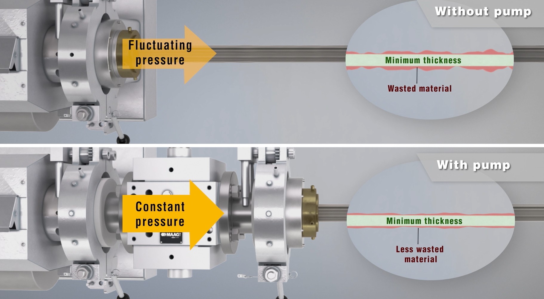
- Drive-speed variation, melt-pump control interaction, or a puller/take-up speed disturbance.
What to check first
- Overlay pressure with screw speed, motor load, feeder output, melt temperature, line speed, and product dimension.
- Compare the oscillation period with feeder refill, screw rotation, heater cycles, screen movement, pumps, pullers, and rolls.
- Check pressure at more than one location when possible to determine where the disturbance begins.
- Verify the pressure transducer and signal before treating the trace as a process problem.
6 Steadily rising head pressure or frequent screen changesBlown FilmCast FilmSheetTubingPipeProfile
What it looks like: Head pressure climbs through the run, output falls, motor load rises, screens require increasingly frequent changes, or product quality deteriorates near the end of each screen cycle.
Likely causes
- Incoming contamination or reclaim load is higher than the filtration area can handle.
- Screen mesh is finer than necessary or the support pack is assembled incorrectly.
- Melt viscosity is higher because of low temperature, resin change, excessive filler, or degraded flow behavior.
- Dead spots upstream are generating char that continuously loads the screen.
- The screen changer, breaker plate, adapter, seal, or flow channel is restricted or damaged.
What to check first
- Use differential pressure across the filtration device rather than only a single upstream pressure reading.
- Inspect and classify the captured material: metal, paper, carbon, cross-linked gels, unmelt, or incompatible resin.
- Compare pressure-rise rate by resin lot, regrind percentage, filtration pack, throughput, and melt temperature.
- Confirm that pressure instruments are installed in useful locations and are reading correctly.
7 Low output or excessive motor loadBlown FilmCast FilmSheetTubingPipeProfile
What it looks like: The line cannot reach historical pounds per hour, motor amperage or torque limits production, head pressure is unusually high, or screw speed increases without a proportional increase in output.
Likely causes
- The extruder is starved by material-handling or feed-throat problems.
- A screen pack, breaker plate, adapter, die, or downstream device creates excessive restriction.
- Melt temperature or resin viscosity is different from the established process window.
- Screw or barrel wear reduces conveying and pumping efficiency.
- The screw design, L/D, mixing section, venting, or drive capacity is not suited to the material and rate.
- Downstream cooling, sizing, haul-off, winding, or quality constraints are the real bottleneck.
What to check first
- Perform a timed mass-output check instead of relying on a nominal extruder rating.
- Compare specific output, such as pounds per hour per rpm, with clean historical runs.
- Review motor load and pressure at each available location to find the restriction.
- Check whether downstream equipment can accept more output without losing dimensions or cooling.
8 Excessive melt temperature, odor, or polymer degradationBlown FilmCast FilmSheetTubingPipeProfile
What it looks like: The melt temperature is higher than barrel setpoints suggest, odor or smoke increases, resin discolors, black specks appear, viscosity changes, or physical properties decline through a long run.
Likely causes
- Excessive shear from high screw speed, restrictive screens, narrow flow passages, or high pressure generation.
- Long residence time at low output, oversized equipment, repeated stops, or stagnant adapters and manifolds.
- Failed heaters, thermocouples, contactors, cooling valves, or poorly located sensors.
- An unsuitable temperature window, contamination, incompatible resin, or too much thermal history in regrind.
- Poor startup, shutdown, or purging practices leave material hot for too long.
What to check first
- Confirm melt temperature with a suitable independent measurement rather than assuming barrel temperature equals melt temperature.
- Calculate approximate residence time and review all low-flow or stagnant regions.
- Compare odor, color, pressure, viscosity indicators, and defect rate from startup through the run.
- Review pressure losses and motor load for evidence of excessive shear work.
9 Unmelted resin or poor melt homogeneityBlown FilmCast FilmSheetTubingPipeProfile
What it looks like: Unmelted pellets, nibs, cloudy streaks, poor color dispersion, unstable pressure, weak spots, or rough surface appear even when the average melt temperature seems acceptable.
Likely causes
- Throughput exceeds the screw’s melting capacity for the resin, pellet geometry, and feed temperature.
- The screw design, compression ratio, barrier section, mixing section, or L/D is not suitable.
- Screw or barrel wear allows solids to pass or reduces mixing effectiveness.
- Large differences in pellet size, regrind shape, filler, color concentrate, or melting point create uneven melting.
- A heater, cooling zone, or temperature sensor is not performing as expected.
What to check first
- Collect and inspect purge at several rates and temperatures for visible unmelt or poor dispersion.
- Inspect material captured at the screen and distinguish unmelt from cross-linked gels or foreign contamination.
- Compare the problem with screw speed, actual output, resin lot, regrind percentage, and startup time.
- Check barrel-zone performance and, when justified, screw and barrel condition.
10 Melt fracture or sharkskinBlown FilmCast FilmSheetTubingPipeProfile
What it looks like: The extrudate develops a rough, matte, ridged, spiraled, or bamboo-like surface. Sharkskin often appears as fine transverse ridges, while severe melt fracture can become irregular and grossly distorted.
Likely causes
- Wall shear stress or shear rate exceeds the critical level for the polymer and die geometry.
- Output is too high for the die gap, land length, entrance geometry, or surface condition.
- Melt temperature is too low for the targeted rate, or viscosity is higher because of resin variation.
- Die lips or lands are damaged, contaminated, misaligned, or poorly finished.
- Processing aid concentration or conditioning is insufficient where such aids are part of the qualified formulation.
What to check first
- Change output in controlled steps and identify whether a repeatable onset threshold exists.
- Compare actual melt temperature and die pressure before and after the defect appears.
- Inspect the die exit and determine whether roughness is uniform or localized to one section.
- Compare resin lot, melt-flow data, regrind level, and qualified additive package.
Die and surface quality
A stationary mark usually points toward a stationary source. Track where the defect first appears before changing multiple settings.
11 Die lines, streaks, or drag marksBlown FilmCast FilmSheetTubingPipeProfile
What it looks like: A continuous line or streak runs in the machine direction or appears at a fixed circumferential position. The line may be glossy, dull, raised, depressed, discolored, or accompanied by a rough patch.
Likely causes
- A nick, burr, scratch, corrosion spot, weld, or damaged coating on the die lip or land.
- Degraded polymer or contamination is attached to the lip, land, mandrel, or manifold.
- Poorly distributed die heat changes local viscosity and flow.
- Foreign material, plate-out, additive buildup, or incompatible resin is dragging the surface.
- Die assembly, centering, cleaning, or polishing introduced a local flow restriction.
What to check first
- Confirm that the line remains in the same cross-web or circumferential position.
- Observe whether the mark changes after a controlled purge, lip cleaning, screen change, or die-temperature stabilization.
- Inspect the lip and land using the plant’s approved shutdown, depressurization, and cleaning procedure.
- Compare the defect with screen debris and recent material, color, or additive changes.
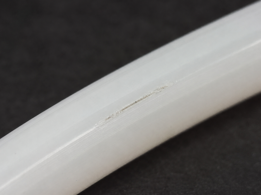
12 Surface scratches, pits, lumps, or dentsCast FilmSheetTubingPipeProfile
What it looks like: The product has scratches, pits, dents, raised lumps, blisters, cracks, or localized roughness. Some defects are continuous; others appear randomly and can escape occasional visual inspection.
Likely causes
- A guide, sizing plate, water-tank component, belt, roll, cutter, or take-up surface is contacting the product.
- Die lines, contamination, unmelt, gels, bubbles, or degraded material create the defect before cooling.
- Debris in cooling water or a damaged sizing tool marks the soft surface.
- Product handling, accumulation, packaging, or offline inspection introduces damage after extrusion.
- Dimensional lumps and neckdowns create apparent surface events or cause contact downstream.
What to check first
- Inspect the product immediately after the die, after sizing, through each cooling stage, before the puller, and after take-up.
- Match repeating defects to roll circumference, belt length, cutter cycle, or other mechanical periods.
- Rotate round product and use multiple views because a single camera or operator may miss the far side.
- Retain defect samples and record line position, time, material, and operating conditions.
Thickness and dimensional control
First determine whether variation is across the product, along the running direction, or random. That pattern narrows the search quickly.
13 Cross-direction thickness variation or gauge bandsBlown FilmCast FilmSheet
What it looks like: The same lane, angular position, or section of the product remains thick or thin. On a wound roll, persistent bands can build hard and soft lanes, taper, bagginess, or a poor roll face.
Likely causes
- Die-gap, lip, mandrel, deckle, or manifold flow is not uniform across the product.
- Blown-film air is blocked, off-center, turbulent, dirty, or affected by drafts and heat sources.
- Cast-film or sheet chill-roll temperature, roll deflection, nip, alignment, or edge cooling is uneven.
- Degraded material, grease, deposits, or thermal imbalance creates a fixed flow or cooling disturbance.
- The thickness measurement is misaligned, poorly calibrated, or not synchronized to an oscillating or rotating process.
What to check first
- Determine whether the high and low areas stay fixed in cross direction or rotate/oscillate through the profile.
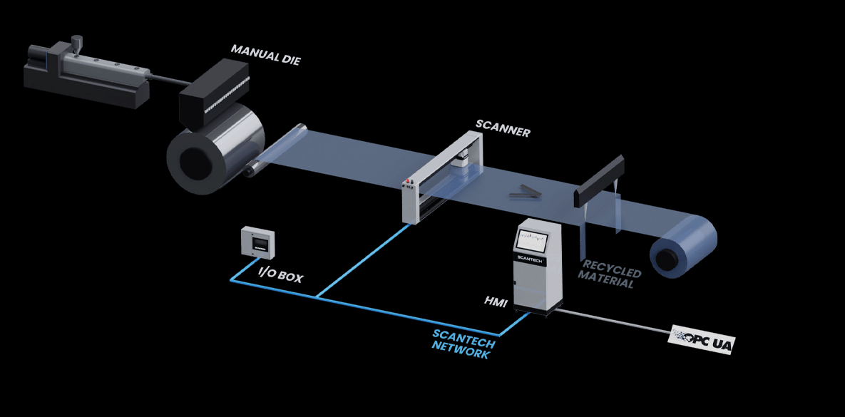
- Overlay profile data with die zones, air-ring sectors, roll zones, and automatic-control outputs.
- Inspect air passages, die lips, heaters, cooling circuits, roll temperatures, and alignment.
- Confirm that the gauge is measuring the intended path and that profile mapping is correct.
14 Machine-direction gauge or dimensional variationBlown FilmCast FilmSheetTubingPipeProfile
What it looks like: Thickness, diameter, wall, width, or weight changes along the running direction. The variation may be slow drift, a repeating wave, or short intermittent events.
Likely causes
- Extruder output is changing because of feed, melting, pressure, wear, screen loading, or drive problems.
- Puller, nip, haul-off, or winder speed varies relative to output.
- Temperature-control cycles change viscosity or cooling at a repeating interval.
- Melt-pump and extruder control loops interact or are tuned poorly.
- The process is operating in a draw-resonance or other viscoelastic instability region.
What to check first
- Calculate the wavelength or time period of the defect at the current line speed.
- Compare that period with screw rpm, feeder refill, pump speed, heater cycles, roll circumference, and drive feedback.
- Trend dimensions with head pressure, pump inlet/outlet pressure, actual line speed, and output.
- Confirm that the measurement sample rate is fast enough to resolve the variation.
15 Uneven wall thickness or poor concentricityTubingPipeProfile
What it looks like: One side of tubing or pipe is thicker than the opposite side, concentricity is poor, flow area shifts, or a product passes OD inspection while wall thickness remains unacceptable.
Likely causes
- Die, tip, mandrel, spider, or crosshead tooling is not centered or is thermally distorted.
- Melt flow or temperature is uneven around the annular passage.
- Gravity sag, uneven cooling, vacuum sizing, internal pressure, or support changes the wall after exit.
- Puller, guide, or cooling-tank alignment deflects the product while it is still soft.
- A single-axis or limited offline measurement misses the true minimum and maximum wall.
What to check first
- Measure wall at multiple angular positions or use a method that resolves the complete circumference.
- Compare hot dimensions near the die with dimensions after sizing, cooling, and puller contact.
- Check tooling centering, temperature symmetry, vacuum or internal pressure, and line alignment.
- Rotate offline samples to distinguish real eccentricity from fixture or measurement bias.
16 Diameter, width, or profile driftBlown FilmCast FilmSheetTubingPipeProfile
What it looks like: The product gradually moves off target over minutes or hours, changes after a speed transition, or requires repeated operator correction as the line warms up.
Likely causes
- Actual mass output and haul-off speed are not maintaining a constant ratio.
- The die, melt, rolls, sizing tooling, cooling water, or surrounding equipment is still reaching thermal equilibrium.
- Resin viscosity, regrind percentage, moisture, or lot changes alter die swell and drawdown.
- Vacuum, internal air, cooling flow, or water temperature drifts through the run.
- Puller slip, belt wear, encoder scaling, or speed-feedback error changes actual line speed.
What to check first
- Record dimensions from startup through steady state along with output, speed, and temperatures.
- Calculate mass per unit length or area to separate true output change from shape change.
- Verify actual line speed independently and inspect puller contact or slip.
- Compare changes with material lot, regrind, dryer condition, vacuum, and cooling-water temperature.
17 Edge bead or excessive neck-inCast FilmSheet
What it looks like: The web narrows more than expected between the die and chill roll, the edges become much thicker than the center, trim loss grows, or the edge profile changes with line speed.
Likely causes
- High drawdown or a long unsupported melt curtain allows the web to contract laterally.
- Melt elasticity, molecular weight, temperature, and formulation increase neck-in behavior.
- Edge pinning, air knives, electrostatic systems, deckles, or edge cooling are misadjusted.
- Die flow is nonuniform near the edges or the deckle creates stagnation and buildup.
- Line speed, chill-roll position, roll temperature, or air gap changes without corresponding process adjustments.
What to check first
- Trend final width, edge thickness, trim rate, line speed, output, and air gap together.
- Inspect both edges separately because asymmetric alignment or cooling can affect only one side.
- Compare the edge response during controlled speed changes and after thermal stabilization.
- Confirm that the thickness gauge captures the edge region with adequate spatial resolution.
Cooling and forming
Dimensions are not finished at the die. In tubing, pipe, and profile work especially, internal air, vacuum, cooling, support, and haul-off can determine the final geometry.
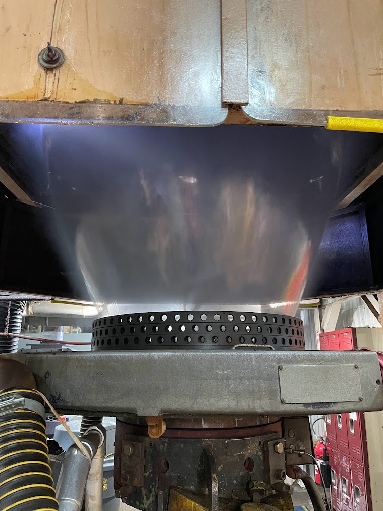
18 Blown-film bubble instability or a moving frost lineBlown Film
What it looks like: The bubble breathes, dances, sways, pumps, changes diameter, develops an uneven or moving frost line, contacts the cage, or sends wrinkles and wander downstream.
Likely causes
- Airflow is uneven, turbulent, blocked, dirty, off-center, or inadequate for the output.
- IBC volume, pressure, exhaust, sealing, or control is unstable.
- Extruder output or nip speed is changing in the machine direction.
- Ambient drafts, doors, fans, heat plumes, leaks, or tower conditions disturb the bubble.
- Blow-up ratio, drawdown, frost-line height, cage setup, or collapsing-frame geometry is outside a stable operating region.
What to check first
- Observe whether the frost line is level and whether motion is circumferential, vertical, or side to side.
- Inspect and clean the air ring, confirm concentricity, and check for local blockages or leaks.
- Trend head pressure, output, nip speed, IBC signals, cooling-air settings, and bubble diameter.
- Walk the tower for drafts, vibration, cage contact, and collapsing-frame drag.
19 Sheet warpage, curl, or uneven coolingCast FilmSheetProfile
What it looks like: Sheet lifts from a flat surface, curls toward one side, bows across width, develops waves, or changes shape after cutting, stacking, reheating, or storage.
Likely causes
- The two surfaces cool at different rates or contact rolls with different temperatures and heat transfer.
- Cross-web thickness variation produces uneven shrinkage and stiffness.
- Roll alignment, nip pressure, deflection, temperature zones, or surface condition is uneven.
- Excessive draw or orientation is frozen into the sheet and releases later.
- Unsupported hot product, poor conveyor support, or uneven downstream air causes distortion.
What to check first
- Note whether curl direction points toward the hotter or cooler side and whether it changes with roll conditions.
- Map top and bottom surface temperatures, cross-web thickness, roll temperatures, and nip settings.
- Compare shape immediately after cooling with shape after conditioning or cutting.
- Check roll alignment, deflection, water flow, scale, surface condition, and edge cooling.
20 Tubing or pipe ovalityTubingPipe
What it looks like: A nominally round product measures differently by axis, rotates between high and low readings, fails fit or sealing requirements, or becomes oval only after the puller, coiler, or packaging step.
Likely causes
- The product enters the puller, guide, coiler, or support while it is too hot and easily deformed.
- Vacuum sizing, internal pressure, sizing-tool condition, or water flow is uneven.
- Uneven wall thickness cools and shrinks differently around the circumference.
- Gravity sag or inadequate support acts on a soft product between the die and sizing or cooling stages.
- Belts, caterpillars, rollers, or coils apply excessive or uneven force.
What to check first
- Measure at least two axes, preferably more, and repeat at the die, after sizing, after cooling, after puller, and after coiling.
- Check product temperature where mechanical contact begins.
- Inspect vacuum stability, sizing-tool wear, water flow, tank alignment, supports, and puller pressure.
- Compare ovality with wall eccentricity to determine whether the shape starts in tooling or downstream.
21Unstable tubing internal air pressure or supportTubingPipe
What it looks like: Tubing OD drifts or oscillates, the hot tube partially collapses before cooling, roundness changes with line speed, or dimensions become unstable even though the puller and extruder appear steady.
Likely causes
- The internal-air regulator is not stable at the low pressure or flow range required by the process.
- Air lines, rotary unions, fittings, tooling passages, or seals leak intermittently.
- A needle valve, filter, small passage, or long line restricts flow and slows pressure response.
- Pressure is measured far from the die, so the displayed value does not represent conditions inside the tube.
- The tube is not sealed consistently downstream, or immersion and cooling conditions change the effective air volume.
- Internal pressure, melt output, line speed, vacuum sizing, and closed-loop OD control are working against one another.
What to check first
- Trend internal air pressure, measured OD, line speed, melt pressure, and actual output on the same time scale.
- Leak-check the regulator, tubing, fittings, die connection, and downstream sealing arrangement.
- Confirm where pressure is measured and whether the sensor range is appropriate for the actual operating pressure.
- Make a small controlled speed or output change and watch whether air pressure and OD recover smoothly or overshoot.
- Determine whether the line uses simple air support, regulated pressure control, or true closed-loop OD control. They are not the same thing.
22 Profile sag, twist, or shape distortionProfile
What it looks like: A profile sags, twists, bows, collapses, changes corner geometry, or meets dimensions at one point but drifts after cooling, cutting, or storage.
Likely causes
- Flow velocity or wall distribution is not balanced across the die exit.
- Different sections of the profile cool and shrink at different rates.
- The hot profile is unsupported, pulled off-axis, or subjected to gravity before it has enough stiffness.
- Vacuum calibrators, sizing plates, spray nozzles, water flow, or contact surfaces are uneven.
- Puller alignment, belt pressure, line-speed changes, or residual orientation distorts the shape.
What to check first
- Use templates or non-contact measurement at multiple points from die exit through final cooling.
- Check whether the direction of twist or sag is repeatable and tied to a specific section of the profile.
- Inspect die balance, calibrator alignment, cooling distribution, support spacing, and puller centerline.
- Run controlled speed changes to see whether cooling capacity or unsupported length is limiting.
23 Draw resonance or periodic thickness oscillationCast FilmSheetTubingProfile
What it looks like: A regular thick-thin pattern repeats along the product even though the die profile is acceptable. The pattern may grow suddenly above a certain line speed or draw ratio.
Likely causes
- The melt is being drawn in an unstable viscoelastic operating region.
- Unsupported distance or draw ratio is too high for the material, temperature, and geometry.
- Take-up, roll, puller, or drive speed oscillates mechanically or electrically.
- Output surging or a control loop creates a similar periodic thickness signal.
- Cooling or solidification occurs too late to damp the instability.
What to check first
- Measure the defect wavelength and convert it to time using actual line speed.
- Compare that frequency with drive feedback, roll circumference, screw speed, feeder cycles, and pressure.
- Change draw ratio, unsupported distance, or speed in controlled steps and document the onset.
- Confirm that the signal is not an aliasing or sampling artifact from the measurement system.
Web handling and winding
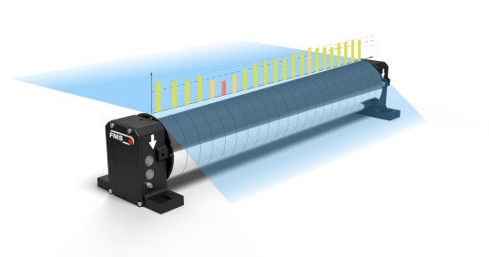
Good extrusion can still become bad product downstream. Tension, alignment, entrained air, and roll build deserve their own diagnosis.
24 Wrinkles, baggy lanes, or uneven web tensionBlown FilmCast FilmSheet
What it looks like: The web develops diagonal, machine-direction, or cross-direction wrinkles, loose lanes, tight lanes, folds, or unstable tension from one side to the other.
Likely causes
- Persistent thickness variation creates long and short lanes across the web.
- Rolls, nips, collapsing frames, spreaders, or winding components are misaligned.
- Tension is too high, too low, or uneven across width and between zones.
- Air is trapped in a layflat, nip, roll, or winding interface.
- Warm film drags on frames, cages, bars, or rolls and stretches unevenly.
- Thermal shrinkage, edge effects, or a poor splice changes the local web length.
What to check first
- Follow the web from upstream to downstream and identify the first roll or zone where the wrinkle appears.
- Compare wrinkle lanes with the thickness profile and roll-hardness pattern.
- Check roll alignment, bearing condition, wrap angles, nip loading, tension by zone, and frame geometry.
- Reduce variables one at a time and avoid using excessive tension to pull wrinkles flat.
25 Web wandering or poor edge alignmentBlown FilmCast FilmSheet
What it looks like: The web shifts laterally, hunts at the guide, runs off-center, changes trim width, misaligns at a downstream process, or winds with an uneven edge.
Likely causes
- A roll, nip, frame, or machine section is not square to the web path.
- Cross-web tension or thickness variation steers the web toward one side.
- The guide sensor is dirty, poorly positioned, seeing a transparent or irregular edge incorrectly, or using the wrong reference.
- The guide actuator is undersized, saturated, loose, slow, or installed with ineffective steering geometry.
- A splice, baggy lane, bubble movement, or changing roll diameter causes a temporary lateral disturbance.
What to check first
- Observe edge position before and after each roll, nip, and guide rather than only at the final winder.
- Check guide correction direction, center position, actuator stroke, sensor alignment, and mechanical looseness.
- Compare lateral movement with tension, profile, splice passage, bubble movement, and roll rotation.
- Confirm that the web has enough entry and exit span for the guide geometry to work.
26 Poor roll build, telescoping, starring, or blockingBlown FilmCast FilmSheet
What it looks like: Roll edges telescope, the roll becomes dished or tapered, cores crush, starring appears, layers block together, or hard and soft bands form across the face.
Likely causes
- Winding tension, torque, nip, taper, lay-on pressure, or speed compensation is incorrect through roll diameter.
- Cross-web thickness variation builds into hard and soft lanes.
- Air is trapped between layers or the film reaches the winder too warm.
- Core quality, chuck expansion, alignment, shaft deflection, or mechanical runout is poor.
- Slip, antiblock, surface treatment, tack, or formulation does not match winding and storage conditions.
- Web wandering, wrinkles, or uneven tension enters the winding zone.
What to check first
- Measure roll hardness and temperature across width and through diameter, not only at the finished surface.
- Compare hard bands with the online thickness profile and profile-control history.
- Review tension, taper, nip, lay-on, air removal, core/chuck condition, and roll alignment.
- Observe the first wraps and startup because early defects can be buried by the finished roll.
Use data to narrow the root cause
A trend that combines process signals and product measurements is much more useful than a collection of isolated setpoints.
Separate an output problem from a draw, haul-off, or geometry problem.
Use the throughput calculatorQuantify spread and centering relative to specifications; use time-ordered data or control charts to assess drift and stability. Evaluate material over-target separately.
Calculate Cpk and PpkDistinguish machine-direction variation from persistent cross-web lanes.
Review thickness measurement optionsUse multi-axis OD measurement to assess ovality and deformation. Evaluate wall distribution with a suitable wall-measurement method to assess wall eccentricity or concentricity.
Review tubing measurement methodsAt minimum, record resin and lot, regrind percentage, recipe, dryer condition, screw speed, actual output, motor load, melt and head pressure, actual line speed, key cooling or vacuum settings, product dimensions, defect rate, and the time of every change. A simple timestamped trend often reveals a correlation that is invisible during a fast-moving production problem.
Extrusion troubleshooting FAQ
What should I check first when an extrusion line suddenly goes out of specification?
First verify material, recipe, actual line speed, actual output, pressure instruments, and any recent screen, die, maintenance, or changeover activity. Then determine whether the defect is machine-direction, cross-direction, or random. That pattern usually narrows the search more effectively than changing temperature zones immediately.
Can a melt pump eliminate extrusion surging?
A properly selected melt pump can reduce pressure variation delivered to the die and separate pressure generation from the extruder. It does not correct bridging, wet resin, poor melting, contamination, screw wear, or an unstable feeder. Diagnose the upstream source even when a pump improves the finished product.
Why does thickness variation sometimes look like a tension problem?
A persistent thick or thin lane changes the effective web length and roll hardness across width. That can create baggy lanes, wrinkles, wandering, and telescoping even when average tension appears reasonable. Compare the tension behavior with the cross-web thickness profile before treating the winder as the only cause.
Why can tubing pass OD inspection but still fail wall or concentricity requirements?
Outside diameter does not reveal the location of the inside surface. A tube can maintain acceptable OD while the ID shifts off-center, creating uneven wall thickness. Multi-axis OD and a wall-thickness method such as ultrasonics are needed when wall distribution and concentricity matter.
Should I raise or lower temperature when surface roughness appears?
There is no universal answer. Roughness may come from melt fracture, contamination, unmelt, degradation, die damage, or physical contact. Verify the defect type, actual melt temperature, pressure, output threshold, die condition, and resin guidance before changing temperature. A change that helps one mechanism can make another worse.
How many process variables should I change during a troubleshooting trial?
Change one primary variable at a time whenever production and safety allow. Record the starting condition, the exact change, response time, and result. Simultaneous changes can produce a good roll without revealing which adjustment mattered, making the problem difficult to prevent later.
Referenced in industry technical resources: GOAFLEX includes this guide in the sources for its TPU film extrusion troubleshooting article, alongside material-specific processing guides from Lubrizol and Covestro.
References used in this guide
This guide combines published technical references with practical diagnostic structure and Gauge Advisor application resources. Material-specific processing windows should always take precedence over general guidance.
- Dynisco, Extrusion Processors Handbook, 2nd Edition. General extrusion fundamentals, melt behavior, moisture, screen packs, gear pumps, melt fracture, process monitoring, and defect finding.
- LyondellBasell, How to Solve Blown Film Problems. Blown-film gauge variation, bubble shape, air-ring effects, wrinkles, and winding defects.
- LyondellBasell, A Guide to Polyolefin Film Extrusion. Polyolefin film materials, equipment, processing, and troubleshooting context.
- Plastics Pipe Institute, Handbook of Polyethylene Pipe, Chapter 4: PE Pipe and Fittings Manufacturing. Pipe extrusion, sizing, cooling, pullers, dimensional control, and production testing.
- Celanese, Celcon Acetal Copolymer Processing and Troubleshooting Guide. Material-specific examples for tubing, film, sheet, and profile extrusion. The recommendations are not universal to all resins.
- ASTM D6988, Standard Guide for Determination of Thickness of Plastic Film Test Specimens.
- ASTM D1238, Standard Test Method for Melt Flow Rates of Thermoplastics by Extrusion Plastometer.
Turn the diagnosis into an equipment plan
If your next step involves equipment, Gauge Advisor can help compare measurement, material handling, melt-pump, filtration, cooling, and web-handling options, define the application details, and coordinate a quotation. Start with the information you have:
- Process and product geometry
- Resin, layers, and regrind percentage
- Line speed and actual output
- Pressure, temperature, and dimensional trends
- Photos or samples of the defect
- What changed before the problem began