Web Tension & Guiding Equipment Selector

Find the right web tension measurement, control, cross-web analysis, or guiding equipment in less than 60 seconds.

1

Choose Your Goal

Select whether you need to measure tension, automatically control tension, analyze variation across the web, or improve web guiding.

2

Describe the Machine

Identify the roller support, control point, web path, material type, and how the recommended equipment should connect to the machine.

3

Add Operating Details

Choose a broad tension range or enter optional values such as minimum and maximum tension, web width, wrap angle, or roller weight.

The correct solution depends on more than tension alone. Roller support, wrap angle, operating range, web width, mounting space, communications, and the specific process problem all influence the recommended force sensors, electronics, controllers, segmented measuring rollers, or web-guiding equipment.

Authorized FMS sales and application support partner

Authorized Sales & Application Support Partner

Find the Right System for Your Process

Gauge Advisor Tool

Web Tension & Guiding Equipment Selector

Find the right equipment for web tension measurement, automatic tension control, cross-web tension analysis, and web guiding.

1What are you working on?

Choose the solution area that best matches the application. We’ll only show the questions needed for that path.

2What should the tension system do?

Choose whether you only need measurement or also want automatic closed-loop control.

3How is the measuring roller supported?

This is the most important detail for selecting the correct force-sensor family.

The Philips PR 9951 is the only documented drop-in replacement path in the supplied standard sheets.

Live-shaft, dead-shaft, cantilever, and unknown pillow-block replacements require dimensional and electrical review.

RMGZ9M covers documented compact combinations up to 500 N. RMGZ9 covers the configurable standard family up to 1,000 N.

4Known force range and conditions

Choose the approximate sensor force or measurement range you already know. If you only know material tension, use the optional calculator below to estimate the resultant force at the measuring roller.

Environment is a compatibility requirement. It can change the sensor family, material, sealing, temperature option, and whether a standard product can be selected.

Standard and optional temperature limits differ by sensor family. A value is required before an elevated-temperature configuration is suggested.

How this works: If you select a known sensor-force range, the selector uses that range directly. If you complete the optional material-tension and wrap-angle calculation below, the calculated force per sensor becomes the primary sizing value and overrides the dropdown.

Calculate from material tension and wrap angle

Calculator priority: A valid calculated sensor force overrides the known range above. If the calculator is incomplete, the selected known sensor-force range remains the sizing basis.
New to material tension? Look for a tension setpoint on the machine HMI or recipe, a handheld tension-meter reading, a process specification stated per unit width, or brake/drive torque data. Material tension is the pulling force in the web; wrap angle converts that known tension into the resultant force acting on the measuring roller.
Choose a known sensor-force range above, or enter maximum material tension and wrap angle to calculate the preliminary force at the sensor.
Need help finding material tension or wrap angle?

Choose the information you already have

Sensor force cannot be determined reliably from web type or speed alone. Start with any tension value already available from the machine, a handheld reading, a process specification, or brake/drive torque. This helper guides you to the right input without guessing.

Use the existing tension value.

Enter the minimum and maximum material tension in the calculator above. Use the machine value as a starting point and note that the tool does not independently verify the setpoint.

Use the measured material tension.

Enter the lowest and highest stable readings from the handheld meter above. Measure under representative running conditions whenever possible.

Use tension per unit width.

The calculator will multiply the entered tension-per-width value by the material width to estimate total material tension.

Estimate material tension from roll torque.

Use net torque acting at the roll whenever possible. Motor torque may require adjustment for gearbox ratio, efficiency, acceleration, bearing drag, and machine losses.

Use 1 when the torque is already stated at the roll.

Enter percent.

Enter torque and roll diameter to estimate material tension.
Application help is the safest next step.

Send Gauge Advisor a machine sketch or photo showing the web path, measuring roller, and any available HMI, brake, or drive information. No standard sensor should be selected until a usable force range is established.

The selected value is a preliminary estimate. Use exact incoming and outgoing directions below when available.

Use exact web-path geometry and speed details (optional)
Material-travel direction convention: Use 0° = right, 90° = up, 180° = left, and 270° = down. The incoming direction is the direction the web travels toward the roller; the outgoing direction is the direction it travels away from the roller. Exact vector geometry takes priority over the simple wrap-angle calculation. Roller weight is incorporated only in this exact-geometry method.

Used only to check red-point alignment and estimate the measured component. Sensor sizing remains based on the full mechanical reaction, not the reduced projection.

Used only with exact incoming and outgoing web directions because weight has a direction.

Add mechanical fit or special-construction details (optional)

Used to narrow the family to documented bearing, journal, or adapter sizes.

5Signal, display, and machine integration

Choose how the measured tension should be viewed or connected to the machine.

6Closed-loop tension control

Choose the machine function, communication method, and housing. One CMGZ controller is required for each independent control zone.

Architecture note: In an FMS closed-loop system, the force sensors connect directly to the CMGZ controller. A separate EMGZ measuring amplifier is not normally required unless an additional independent monitoring path is requested.

7Cross-web tension analysis

For a complete-system review, choose whether segmented cross-web measurement should be included.

8Cross-Web Tension Setup

Tell us how the material runs so we can estimate the roller layout, measuring zones, and sleeve widths.

9Data and Engineering Details

Choose the PLC interface and visualization path. Exact tension values and wrap angle are optional and are not used to finalize segment force ranges.

Standard segFORCE electronics are IP40 and rated –10 to +50°C.

Operating conditions

Important: Any force-per-zone value shown by the selector is an even-distribution reference only. segFORCE nominal force, sleeve position, and grouping must be confirmed with FMS.

9Web guiding requirements

Tell us where correction should occur, what the system should track, and how the web will be detected.

Select all that apply. A line may need separate guiding at the running web, unwind, and rewind.

Standard BKS015 uses integrated control electronics. BKS030 and winderGLIDE stations use external BKS309 control electronics.

Size the two stands separately. Unwind and rewind moving mass, friction, and travel often differ.

Unwinder actuator

Rewinder actuator

The guide reference and sensor family selected above are applied to all chosen stations. If the unwind, running web, and rewind use different references or materials, request a station-by-station application review.

Running-web and sensor details

Recommended equipment

One primary recommendation is provided per equipment category, with alternates only when a meaningful tradeoff exists. Final sizing should be reviewed with Gauge Advisor and confirmed with FMS.

Application review recommended

Final force-sensor sizing, system configuration, and integration details should be reviewed with Gauge Advisor and confirmed with FMS using the actual machine layout, resultant force, roll weight, wrap angle, web path, speed, environment, and PLC requirements.

Gauge Advisor is an authorized sales and application support partner for FMS.
Why engineers choose FMS
Precise, stable measurement: Full-bridge strain-gauge designs provide strong signal quality, repeatability, and resistance to temperature and electrical-noise effects.
Built for demanding production: Mechanical overload protection and application-specific sensor designs help reduce damage, downtime, and recalibration risk.
Mechanical arrangement first

Live-shaft, dead-shaft, pillow-block, and cantilever installations use different force-sensor families. Force range is used later to size the selected family.

Performance breaks the overlap

Compactness, precision, wide operating range, environment, and replacement requirements distinguish products that share similar nominal-force ratings.

Cross-web analysis uses a complete roller

The segmented measuring roller follows its own configuration path and does not use the live-shaft, dead-shaft, or pillow-block force-sensor questions.

The output is a system

Depending on the goal, recommendations may include a force sensor, measuring amplifier, tension controller, segmented roller, steering system, material sensor, and guide controller.

Web Tension & Guiding Systems Overview

FMS Technologies at a Glance

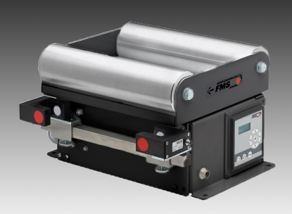
The selector above recommends a preliminary equipment configuration. Below is a visual overview of the primary FMS technologies used for web tension measurement, automatic tension control, cross-web tension analysis, and web guiding.

FMS force measuring bearing for live shaft web tension measurement

Live-Shaft & Dead-Shaft Rollers

Force Measuring Bearings

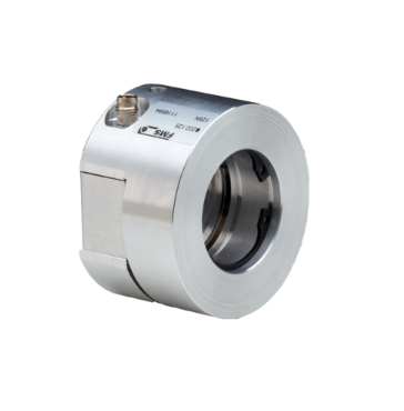
Compact strain-gauge sensors installed at the ends of a measuring roller. FMS offers live-shaft and dead-shaft designs for general-purpose measurement, compact installations, high precision, and applications with very wide operating tension ranges.

FMS UMGZ pillow block force sensor for web tension measurement

External Bearing Housings

Pillow-Block Force Sensors

Force-measuring blocks installed beneath external pillow-block bearings. Standard, retrofit, hermetically sealed, high-temperature, paper, and metal-processing configurations are available.

FMS RMGZ9 cantilever measuring roller for web tension measurement

Compact One-Sided Installation

Cantilever Measuring Rollers

Complete force sensor and roller assemblies supported from one side. Cantilever rollers simplify installation where machine space is limited or open access to one side of the web is preferred.

FMS CMGZ309 closed loop web tension controller

Automatic Closed-Loop Control

Web Tension Controllers

Closed-loop controllers maintain consistent web tension by regulating unwind brakes, unwind drives, intermediate drives, or rewind drives as operating conditions and roll diameter change.

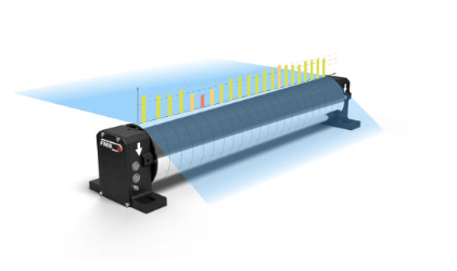
FMS segFORCE segmented roller for cross web tension analysis

Cross-Web Tension Profile

FMS-segFORCE

A segmented measuring roller that provides independent tension readings across the width of a continuous web or individual slit lanes. It helps identify uneven tension, baggy edges, wrinkles, winding problems, and material-related variation that conventional end-mounted sensors may not reveal.

FMS webMASTER steering frame for web guiding

Edge, Center & Line Guiding

Web Guiding Systems

Steering frames and winderGLIDE actuators correct lateral web position by tracking an edge, web center, or printed reference line. Systems can guide the running web or shift an unwind or rewind stand.

Electronics, Controls & Material Detection

Choose How the System Is Monitored and Controlled

After the mechanical equipment is selected, the next step is choosing how force signals are processed, how tension or web position is controlled, and how information is communicated to the machine.

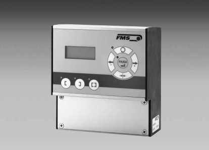
FMS measuring amplifier for web tension force sensors

Signal Processing

Measuring Amplifiers

Convert the millivolt signal from FMS force sensors into a usable analog, digital, or industrial-network output. Single-channel and multi-channel versions are available.

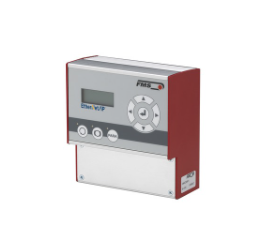
FMS tension controller with EtherNet IP communication

Closed-Loop Regulation

Tension Control Electronics

Compare measured tension with the target setpoint and continuously adjust the brake or drive. Standalone and EtherNet/IP-compatible controller options are available.

FMS BKS309 web guide controller

Position Control

Web Guide Controllers

Process the material-position signal and control the steering frame or actuator. Standard Ethernet and EtherNet/IP versions support standalone operation or machine integration.

FMS ultrasonic material sensor for web guiding

Edge, Center & Line Detection

Material Sensors

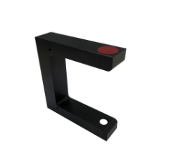
Ultrasonic sensors detect clear and transparent webs, optical sensors accurately track opaque material edges, and digital line sensors follow printed lines or registration marks.

Selection note: Final force-sensor sizing, nominal-force rating, mounting arrangement, wrap angle, roller weight, amplifier selection, tension-control setup, web-guide configuration, and communications should be reviewed with Gauge Advisor and confirmed with FMS before quotation or installation.

Gauge Advisor is an authorized FMS sales and application support partner. We help customers evaluate the application, select the appropriate equipment, coordinate final factory review, and support the system through quotation and implementation.

Next Step After the Selector

Confirm the system with the real machine conditions

The selector provides a strong preliminary equipment path. Final sizing and configuration should also consider the roller arrangement, wrap angle, roller weight, operating tension range, material behavior, available mounting space, and machine-control requirements.

Why This Matters

Web tension problems are not always visible in the same way

Stable web tension and lateral position can directly affect coating uniformity, registration, winding quality, wrinkle formation, web breaks, and overall process repeatability. The right system should match both the mechanical layout and the process problem being addressed.

Incorrect sensor sizing: A force sensor may fit the stated tension range but still be poorly matched if roller weight, wrap angle, or the direction of the resulting force is not considered.

Hidden cross-web variation: Conventional force sensors measure the total force at the roller ends and may not reveal localized loose edges, baggy areas, or uneven slit-lane tension.

System mismatch: Tension measurement, closed-loop control, cross-web analysis, and lateral web guiding solve different problems and often require different combinations of sensors, electronics, controllers, and mechanical equipment.

Tension measurement

Force sensors and measuring amplifiers provide continuous visibility into web tension at an unwind, process section, driven roll, or rewind.

Automatic tension control

Closed-loop controllers compare measured tension with the target setpoint and automatically regulate an unwind brake or machine drive.

Cross-web tension analysis

A segmented measuring roller provides separate tension values across a continuous web or individual slit lanes to reveal localized variation.

Web guiding

Material sensors, controllers, steering frames, and actuators keep the web edge, centerline, or printed reference in the correct lateral position.

System Architecture

Decide how the signal should be used

After selecting the mechanical equipment, the next decision is whether the signal should be displayed locally, sent to a PLC, recorded for analysis, or used for automatic control.

Monitoring

Measuring Amplifier

Converts the force-sensor signal into a usable analog, digital, or industrial-network output for display or machine integration.

Automatic Regulation

Tension Controller

Uses measured tension to regulate a brake or drive and maintain the target setpoint as speed and roll diameter change.

Analysis & Integration

PLC, HMI & Software

Supports real-time machine communication, operator visualization, production-data logging, tension profiles, and process troubleshooting.

Common Questions

Quick answers before application review

What is the difference between live-shaft and dead-shaft sensing?

On a live-shaft roller, the shaft rotates with the roller. On a dead-shaft roller, the shaft remains stationary while the roller rotates around it. The support arrangement determines which force-sensor family is appropriate.

Why are wrap angle and roller weight important?

The force applied to the sensor depends on more than web tension alone. Wrap angle, roller weight, mounting direction, and machine geometry all influence the resulting load at the sensor.

When is cross-web tension analysis useful?

It is especially useful when troubleshooting wrinkles, baggy edges, unequal slit-lane tension, winding defects, inconsistent parent rolls, or variation that conventional end-mounted sensors cannot isolate.

Is web guiding the same as tension control?

No. Tension control regulates the force applied to the web. Web guiding corrects its lateral position. Many production lines benefit from both systems working together.

Ready for the Next Step?

Use your selector results to start the application review

Gauge Advisor can review your preliminary recommendations, evaluate the machine and process details, and coordinate with FMS to confirm the final force-sensor sizing, electronics, control architecture, web-guiding equipment, and system configuration.

Gauge Advisor is an authorized FMS sales and application support partner.