Updated August 21, 2026
Blown film gauge variation is rarely one problem with one adjustment. A persistent thick band may come from the die, the air ring, or incorrect profile mapping. A whole-profile shift may start upstream with output or haul-off speed. A stable thickness profile can still produce hard bands, wrinkles, or baggy lanes if downstream tension is uneven. The fastest path to improvement is to identify the pattern first, then match the correction to the part of the line that actually created it.
Connected process path: Blown-film gauge stability is a full-line result: consistent blending and throughput feed a stable melt, while cooling, measurement, and web handling correct the remaining variation.
Related next steps: continuous gravimetric blenders, throughput-control weigh hoppers, film and sheet melt delivery, blown-film gauge control, web tension and guiding selector, central resin conveying systems, and film-scrap repelletizing.
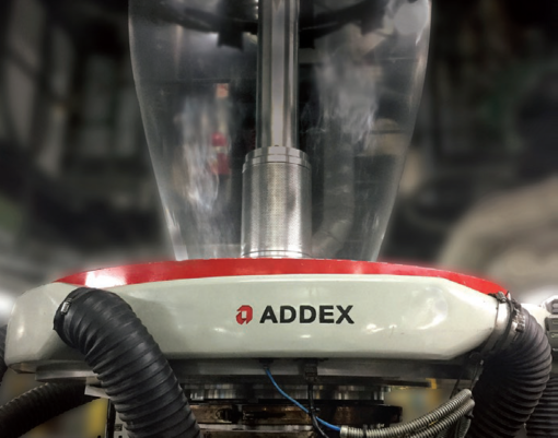
Four different problems are often called “gauge variation”
Before comparing air rings or control systems, separate the variation by direction and by where it appears. This single step prevents a great deal of unnecessary adjustment.
Thick and thin zones repeat around the bubble. After collapse and layflat deconvolution, this appears as a cross-web profile and is the primary target for localized air-ring gauge control.
The entire profile rises and falls over time. Typical sources include extruder surging, feed variation, melt-pressure changes, haul-off speed, or a changing average target.
Frost-line height, layflat width, bubble shape, or breathing changes during the run. The profile may move because the cooling environment itself is not stable.
The scanner profile may look acceptable while the finished roll develops bands, wrinkles, telescoping, or baggy lanes. That is a web-handling problem, a profile problem amplified by tension, or both.
Industry troubleshooting guidance similarly separates machine-direction gauge changes from transverse or circumferential gauge bands and notes that bubble shape and frost-line behavior are useful clues to the source of variation.[9] For a wider process diagnosis that includes feed, pressure, die, cooling, haul-off, and winding, use the Plastics Extrusion Troubleshooting Guide.
Follow gauge variation from the resin silo to the winder
Click a stage to see the profile patterns it can create, the first checks I would make, and the equipment path that may be relevant. A thickness scanner is most valuable when its data is synchronized with the rest of the line.
1. Resin, blending, and feed: verify the process entering the screw
Changes in resin rheology, blend ratio, additive concentration, regrind condition, moisture, bulk density, or feeder output can appear later as average-gauge drift, bubble movement, optical changes, or unstable output. An air ring cannot make an intermittently starved extruder produce a stable mass flow.
- Compare the event with lot changes, hopper refill, blender cycles, regrind percentage, and additive feed.
- Trend extruder output indicators before changing the die or air ring.
- Confirm that a multilayer line is holding each layer ratio, not only total thickness.
What does the thickness profile actually look like?
Select the pattern that most closely matches the scanner, bubble, or finished roll. The chart is illustrative. Use synchronized production data and physical samples before concluding that one component caused the problem.
Fixed thick or thin band
A persistent band at one angular location usually points toward a repeatable circumferential source: die flow, die temperature, contamination, a dirty or off-center air ring, a draft, or a local cooling imbalance. The key question is whether the band stays fixed to the die, the air ring, the room, or the finished roll.
Level and center the die and air ring, inspect lip and airflow condition, mark bubble orientation, and compare the band with die or air-ring rotation.
Addex MGC can support manual local airflow correction. Addex EGC is the automatic path when a mapped scanner profile and closed-loop correction are required.
A severe damaged or contaminated die may need cleaning or repair before any air-based control system can hold the desired profile.
Cooling, measurement, control, and tension solve different parts of the problem
A complete gauge-control strategy is not one sensor or one air ring. Addex changes the cooling and bubble-control environment. Scantech measures and maps the thickness profile. FMS measures and controls the web after collapse so that a good profile is not lost during handling and winding.
Act on cooling and bubble behavior
Air rings, Intensive Cooling, Manual Gauge Control, External Gauge Control, Digital IBC, cage control, and rotation mapping address the part of the process where the bubble is cooled, shaped, stabilized, and locally corrected.
- Improve external cooling and bubble locking
- Correct persistent polar profile zones
- Coordinate IBC, layflat, cage, and rotation
Measure the profile that the control loop needs
Low-energy X-ray measurement at the layflat can deconvolve the double layer and map the reconstructed profile back to the die or air-ring control zones.[6]
- Profile and average thickness visibility
- Fast mapped data for automatic control
- Trend, alarm, recipe, and quality records
Preserve quality through the web path
Conventional force sensors measure total web tension, while segmented measurement can reveal tension differences across the width. Tension does not replace gauge control, but it can expose and reduce winding defects that make profile problems more severe.
- Average tension measurement and control
- Cross-web tension profile with segFORCE
- Winding, guiding, and downstream stability
Build a preliminary gauge-variation equipment path
Choose the symptom, current measurement, line motion, cooling condition, and roll-quality problem. The tool provides a practical starting architecture. It does not replace a line review, profile files, equipment drawings, or factory application confirmation.
Match blown film symptoms to likely causes and the right next step
Search by symptom, material, component, or technology. The matrix separates the defect pattern from the proposed equipment path so that the commercial recommendation follows the diagnosis.
| Symptom or pattern | Likely causes | What to check first | Equipment path and Gauge Advisor resource |
|---|---|---|---|
One persistent thick or thin band Polar profile | Local die-flow variation, die temperature, contamination, damaged lip, off-center air ring, dirty airflow passage, room draft, or local cooling imbalance. | Mark bubble orientation; level and center the die and air ring; inspect lip, vane, and airflow condition; determine whether the band stays with the die, air ring, or room. | After mechanical checks, evaluate Addex MGC for economical manual correction or Addex EGC for automatic high-resolution correction. Start with the Blown Film Air Ring Selector. |
Two high zones and two low zones Tooling pattern | Die assembly, mandrel centering, side-fed flow pattern, air-ring centering, thermal asymmetry, or a repeatable multi-lobe cooling condition. | Verify die assembly history, centering, thermal zones, air-ring level, and whether the lobes rotate with the die. | Correct severe mechanical causes first. MGC or EGC can trim remaining repeatable profile error when the die and cooling hardware are fundamentally sound. |
Profile moves with a rotating die Rotation mapping | A die-fixed profile feature, correct physical rotation but incomplete mapping, wrong phase, wrong direction, or lag between measured location and actuator position. | Confirm rotation encoder, direction, zero, speed, scanner-to-air-ring transport delay, and whether the profile follows the die at the expected rate. | Addex Gen3 EGC is designed to coordinate rotation and high-resolution airflow control on rotating-die lines.[4] |
Profile stays fixed while die rotates Stationary influence | Stationary air-ring body, room draft, enclosure leak, fixed obstruction, nonrotating cooling imbalance, scanner mapping error, or downstream distortion. | Watch the frost line and thick band relative to fixed room features; inspect air hoses and enclosure; verify mapping direction before changing die settings. | Evaluate the cooling hardware and mapping. Addex air-ring review may be appropriate when the error is tied to the stationary cooling system. |
Whole average gauge cycles up and down MD variation | Feed or blender cycle, extruder surging, melt-pressure variation, screw-speed regulation, haul-off speed, IBC volume change, or unstable average-gauge control. | Trend average thickness against output, P1/P2 where available, screw speed, motor load, feeder data, nip speed, layflat, and frost-line height. | Do not ask a polar air-ring control to fix an upstream MD problem. Use the Pressure Fluctuation Guide and review average-gauge control separately. |
Random spikes or an unusually noisy profile Signal or transient | Web flutter, folds, scanner contamination, calibration issue, double-layer deconvolution challenge, transient gels, moisture, electrical noise, or unstable process data. | Compare raw sensor signal, scanner mechanics, web position, cleaning, calibration, and physical film samples. Determine whether the event repeats at the same width position. | Review the measurement application before tuning the control loop. See the Web Gauging Technology Guide. |
Frost line is tilted or uneven Cooling clue | Air-ring level or centering, uneven airflow, draft, die thermal variation, bubble cage contact, IBC imbalance, or uneven melt distribution. | Level and center the die and air ring; observe whether high and low frost-line areas align with gauge bands; inspect room air and cooling passages. | Addex LFR, MGC, EGC, or Intensive Cooling may be evaluated after setup and maintenance checks. Use the air-ring selector to narrow the architecture. |
Layflat width breathes or drifts Bubble control | IBC supply or exhaust instability, leak, nip seal, cage control, bubble motion, output changes, ambient conditions, or incorrect bubble-size control. | Trend layflat, IBC supply/exhaust, internal pressure, frost line, output, cage position, and nip condition on the same time base. | Evaluate Addex Digital IBC and integrated bubble/cage control when the internal cooling and size-control architecture is the limiting factor. |
Higher output destabilizes the bubble Cooling limit | External cooling capacity, weak bubble locking, high unsupported hot length, IBC limitation, tower environment, polymer melt strength, or air-system capacity. | Record output, frost-line height, blower operating point, air temperature, bubble motion, BUR, die size, material, and when instability begins. | Evaluate Addex icLFR, icMGC, icEGC, or a Short Stack / Intensive Cooling architecture. Use the Air Ring ROI Calculator to frame the financial case. |
Startup and grade changes take too long Manual correction | Offline sampling delay, manual die or MGC adjustment, slow thermal actuation, no stable profile map, recipe variability, or operator-to-operator differences. | Measure time to first usable profile, number of adjustments, scrap pounds, response delay, and whether the process is stable before each correction. | A Scantech layflat scanner plus Addex EGC can create a faster automatic profile loop. MGC remains an economical option when manual correction is acceptable. |
Scanner profile changes after speed changes Delay and mapping | Transport delay changes with line speed, wrong control delay, scan estimation, phase error, process response, or average-profile separation. | Measure distance from correction point to scanner, actual line speed, scan time, rotation rate, and time from actuator movement to measured response. | Review Scantech measurement timing and Addex control mapping as one system. CD control is strongly affected by delay and actuator-to-sensor mapping.[12] |
Thickness profile looks stable but roll has hard bands Profile or winding | Small persistent gauge bands, excessive winding tension, taper-tension settings, roll hardness, oscillation distribution, or cross-web tension variation. | Compare thickness profile, roll hardness, winding tension, and band location. Reduce neither tension nor gauge blindly until the dominant cause is known. | Use Scantech data to verify the profile and FMS tension measurement to verify the winding condition. Consider segFORCE when the problem differs across the width. |
Wrinkles, telescoping, or unstable roll build Average tension | Low or high web tension, poor taper tension, drive or brake response, roller alignment, guiding, nip condition, or an uneven thickness profile. | Measure tension rather than relying only on torque or dancer position. Review wrap angle, roller alignment, drive response, roll diameter, and profile data. | Use the Web Tension & Guiding Selector to screen FMS sensors, controllers, and guiding equipment. |
Baggy lanes or uneven tension across the width Cross-web tension | Gauge bands, uneven orientation, collapsing-frame geometry, roll condition, differential stretch, misalignment, or material-related tension variation. | Compare the cross-web thickness profile with a cross-web tension profile and inspect whether the same zones stay high or low over time. | FMS segFORCE provides up to 50 tension measurement points across the web for process diagnosis.[8] |
Film is always run heavier to protect the minimum Resin giveaway | High profile sigma, thin outliers, unreliable measurement, conservative setup, poor capability, slow correction, or a specification that is not tied to process data. | Calculate average, minimum, maximum, standard deviation, Cpk/Ppk, pounds per area, and the actual commercial thickness definition. | Use Scantech measurement to quantify the profile, Addex control to reduce polar variation where appropriate, and the calculator below to estimate directional resin savings. |
Multilayer film total gauge is stable but layer performance changes Coextrusion | Layer-ratio drift, individual extruder output, resin or density change, feedblock/die distribution, barrier-layer variation, or calibration model mismatch. | Trend each extruder and feeder, confirm layer ratios, compare physical testing, and determine whether the online system measures total thickness or a selected layer/property. | Review the Scantech measurement architecture and calibration feasibility. Total thickness control cannot by itself prove every layer is stable. |
Choose the Addex architecture from the control problem
Addex is the primary equipment path when gauge variation is tied to external cooling, bubble stability, local polar-profile correction, internal bubble cooling, or profile mapping on rotating and oscillating equipment. The product names matter less than whether the line needs better base cooling, manual correction, automatic correction, higher output, or integrated bubble control.
LFR and icLFR
Laminar Flow air rings provide the external cooling foundation when the primary goal is stable, efficient cooling without manual or automatic local profile actuation.
- New line or retrofit air-ring review
- Stationary, rotating, or oscillating applications
- Intensive Cooling option when output and bubble locking are limiting
MGC and icMGC
Manual Gauge Control uses closely spaced adjustable air vanes so operators can trim repeatable thick and thin zones through local airflow rather than repeated die-bolt changes. Addex reports typical customer thickness-variation reductions of 20% to 30%, with results depending on the line and starting condition.[2]
- Lower-cost profile improvement
- Best when manual sampling and adjustment are acceptable
- Can be paired with Intensive Cooling
EGC and icEGC
External Gauge Control automatically changes localized airflow around the bubble using high-resolution control fingers. It is the strongest Addex path when the line has a reliable mapped thickness profile and needs closed-loop polar correction.
- High-resolution local airflow actuation
- Stationary, oscillating, and supported rotating-die architectures
- Scanner, mapping, delay, and rotation data must be correct
Intensive Cooling and Short Stack
Intensive Cooling adds stronger bubble holding and increased heat-transfer capacity through additional divergent cooling elements. Addex publishes application-dependent output gains for ic air rings and multi-level stacked configurations; actual results must be confirmed from die size, material, BUR, air system, tower, and product requirements.[1]
- Cooling-limited output
- High frost line or weak bubble locking
- Output and quality should be evaluated together
Digital IBC and icDIBC
Digital Internal Bubble Cooling coordinates supply and exhaust air to stabilize bubble size, internal cooling, and layflat behavior. It is relevant when the internal loop, not only the external air ring, is causing breathing or size drift.[3]
- Layflat and bubble-size control
- Internal heat removal and stability
- Integration with cage and line controls
Gen3 mapping and integrated controls
On rotating-die lines, the measured profile must be mapped to moving physical zones. Addex Gen3 coordinates die rotation and EGC mapping so the correct air-ring zone responds to the correct thickness band.[4]
- Rotation direction, zero, speed, and phase
- Transport delay from air ring to scanner
- Integrated IBC, cage, layflat, and profile view


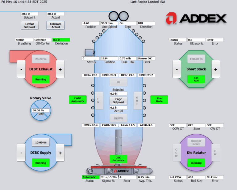

A published Addex case study on a rotating-die line reported a reduction in scrap from 18% to 22% before the installation to 6% during the later reporting period. That is a useful example, not a guaranteed result for every line.[5] The 60-Second Blown Film Air Ring Selector is the best next step when you already know the die size, materials, output, gauge problem, and current air-ring or IBC arrangement.
The scanner is the eyes of the profile-control loop
Automatic correction is only as good as the profile sent to the controller. On a blown film line, the scanner sees a moving, collapsed double layer rather than a stationary single sheet. The measurement system must separate machine-direction behavior from the reconstructed polar profile and map that profile back to the physical control zones.
Low-energy X-ray at the layflat
Scantech applies low-energy X-ray measurement on an O-frame after collapse. The layflat location provides a mechanically accessible and stable web path compared with chasing the moving bubble.
Deconvolve the double layer
Specialized algorithms separate the combined layflat measurement into a stable profile that can be mapped back to the die or air ring.[6]
Respect delay and movement
The control system must account for scan time, line speed, distance from air ring to scanner, die or haul-off motion, actuator response, limits, and the difference between average and polar variation.

For a deeper comparison of X-ray, beta, gamma, infrared, optical, and ultrasonic web measurement, see the Web Gauging Technologies Guide. For the blown-film-specific measurement case, see Blown Film Thickness Measurement: Why X-Ray Gauging Is Preferred at the Layflat.
Do not confuse gauge variation with the damage it creates during winding
Thickness bands change how the web stretches and builds on the roll. Tension can make those bands more pronounced, and poor tension can create defects even when the thickness profile is good. The two data sets should be compared rather than treated as substitutes.

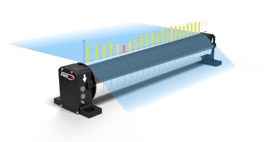
Two force sensors on an idler roll measure the total roller load produced by the web path. FMS notes that too little tension can contribute to wrinkles, while too much can stretch or break the web.[7]
A conventional roller cannot show every lane or zone. FMS segFORCE can provide up to 50 measuring points across the width, helping correlate baggy lanes, parent-roll quality, and process faults with the thickness profile.[8]
FMS controllers can regulate unwind, intermediate, or rewind tension, while guiding equipment corrects lateral position. These functions preserve web quality after the bubble has been collapsed.
Use the Web Tension & Guiding Equipment Selector when the symptoms involve wrinkles, roll build, web breaks, drifting edges, or unknown force-sensor sizing. For a deeper look at cross-web tension measurement, read Controlling Web Tension with a Segmented Tension Roller.
The same hardware can behave differently with a different film recipe
Do not copy one air-ring setting, frost-line target, gain, or profile threshold from another polymer and assume it applies. Melt strength, crystallization, viscosity, density, additives, layer structure, regrind, and optical response all change the process.
Blend ratio changes draw behavior, melt strength, clarity, seal properties, and the cooling window. Slip, antiblock, color, and metallocene content can also change bubble behavior and scanner calibration.
High-stalk bubbles and stronger orientation make frost-line shape, air-ring balance, cage alignment, and cooling conditions especially important. Process symptoms may not look like LDPE film.
Crystallization, temperature window, cooling rate, and stability can differ substantially from polyethylene. Verify the complete product envelope before promising output or profile gains.
PA, EVOH, tie layers, and other barrier structures add individual extruder and layer-ratio risks. A stable total gauge does not prove that the critical barrier layer is stable.
Bulk density, contamination, MFR, moisture, additive carryover, and filler percentage can vary. Separate composition and feed instability from the cooling correction problem.
Orientation, coefficient of friction, tack, winding tension, and downstream performance can make a small profile band commercially important even when the nominal gauge remains in tolerance.
LyondellBasell’s film-extrusion guide discusses how polymer structure, additives, die design, cooling, IBC, oscillating haul-off, gauge measurement, and winding interact across the line.[10] Use supplier processing guidance and plant trials for actual temperature, BUR, output, and cooling settings.
Estimate the directional value of lowering the average gauge
When profile variation is reduced, the average target may be moved closer to the required minimum while maintaining the customer specification. This calculator estimates resin savings from that average-gauge change. It does not assume that every line can safely make the change.
Important: Do not lower the average target unless the measured profile, minimum thickness, capability, physical properties, customer specification, and validation data support the change. Film thickness definitions and laboratory methods should be controlled; ASTM D6988 provides general thickness-measurement guidance for plastic-film test specimens.[11]
Build the baseline before requesting equipment
A strong application review starts with actual line data. The objective is not to prove that one partner’s product is always the answer. It is to show where the variation originates and what the proposed system would be expected to change.
- Product and polymerLayer structure, resins, density, MFR, additives, filler, regrind/PCR, target gauge, minimum gauge, and product family.
- Die and bubbleDie diameter, die type, gap, BUR range, layflat range, frost-line range, tower height, cage, enclosure, and ambient drafts.
- Output and coolingCurrent and target output, blower capacity, air pressure, air temperature, air-ring type, IBC type, and the condition that limits rate.
- Profile and measurementVariation definition, current plots, scanner type and location, scan time, calibration, double-layer method, average gauge, and mapping method.
- Rotation and movementStationary, rotating, or oscillating die; oscillating haul-off; rotation range, speed, encoder, zero, direction, and existing controller.
- Web handlingCollapsing frame, nip, roller path, tension setpoints, load cells, winder type, taper tension, guiding, roll hardness, wrinkles, and baggy lanes.
- Economic baselineAnnual resin use, resin cost, scrap, startup pounds, lost output, labor, changeover time, customer claims, and current average over-gauge.
- Integration and supportPLC, communications, HMI, available space, drawings, utilities, safety, installation scope, startup needs, training, and service expectations.
Common mistakes when troubleshooting blown film gauge variation
Adjusting the die before confirming the air ring is centered and level
A tipped, dirty, leaking, or off-center air ring can create a thickness pattern that looks like a die problem. Industry troubleshooting guidance specifically notes that off-center or tipped air rings can create gauge variation similar to poor die adjustment.[9]
Treating machine-direction variation as a polar-profile problem
If the whole average rises and falls, check feed, extrusion output, pressure, and haul-off speed. Local air-ring zones are not the primary actuator for an unstable total mass flow.
Assuming rotation or oscillation eliminates gauge variation
Rotation distributes persistent profile error around the finished roll. It may improve roll build, but it does not remove the underlying thick and thin areas. Automatic control must also know where the rotating error is located.
Running heavier instead of reducing profile variation
Increasing average gauge protects the minimum, but it also hides poor capability and permanently adds resin cost. Use measured minimum, sigma, Cpk/Ppk, and product performance to determine whether the average can be lowered safely.
Using scanner data without validating mapping and delay
A correct thickness value applied to the wrong angular zone can make the profile worse. Confirm scanner location, line speed, rotation, phase, zero, direction, scan time, control delay, and actuator response.
Expecting the scanner to fix the line by itself
The scanner measures. The correction requires a suitable actuator, control model, limits, stable process, and a defined response when the control loop cannot overcome the disturbance.
Blaming every poor roll on tension
Tension can cause wrinkles, stretching, breaks, telescoping, and roll-build problems, but a thickness band can create a tension profile of its own. Compare Scantech thickness data with FMS tension data before choosing the correction.
Using one recipe for every resin and structure
LDPE, LLDPE, HDPE, PP, barrier structures, PCR, filled film, and specialty films do not share one cooling or control window. Use product-specific recipes and revalidate when the structure changes.
Turning manufacturer case results into guaranteed plant results
Addex publishes strong output, variation, and scrap-reduction examples. Those examples establish technical potential, not a universal guarantee. Final expectations should be tied to the baseline, product envelope, line condition, and agreed application scope.
Tracking only max-minus-min
Max-minus-min is useful but sensitive to outliers. Also track average, standard deviation, profile shape, repeatability, minimum, Cpk/Ppk, startup time, scrap, and the commercial roll defects that matter to the customer.
Related Gauge Advisor tools and technical resources
Use the selector when you need an equipment path, the calculator when you need the business case, and the deeper article when one part of the line has already been isolated.
Blown film gauge-variation FAQs
What is an acceptable amount of blown film gauge variation?
There is no universal percentage. The acceptable range depends on how variation is calculated, customer minimums, product performance, average target, sampling method, process capability, and downstream converting requirements. Define the metric before comparing lines or supplier claims.
What is the difference between MD and polar or cross-direction variation?
Machine-direction variation changes along the length of the film and often appears as the whole average moving over time. Polar variation changes around the bubble circumference and appears as a cross-web profile after the layflat is reconstructed. The causes and actuators are different.
Can an air ring correct a bad die?
An Addex MGC or EGC can correct meaningful repeatable profile variation through airflow, but it cannot make a severely damaged, contaminated, misassembled, or unstable die behave like new. Mechanical and process defects should be corrected first when they exceed the control authority.
What is the difference between Addex MGC and EGC?
MGC provides closely spaced manual airflow adjustments and is an economical path when operator sampling and correction are acceptable. EGC motorizes high-resolution airflow zones and uses mapped online thickness data for automatic closed-loop correction.
Can Addex EGC work with a rotating die?
Yes, Addex offers a Gen3 EGC architecture for supported rotating-die applications. The system coordinates die rotation and profile mapping so the measured band is assigned to the correct moving control zone. Final compatibility depends on the existing rotation, controller, scanner, line layout, and die size.
Does Intensive Cooling automatically reduce gauge variation?
Intensive Cooling is designed to increase cooling capacity and bubble stability. Better stability can improve the environment for gauge control, but the profile also depends on the die, airflow balance, material, IBC, scanner, mapping, and downstream line. Output and profile should be evaluated together.
Do I need an online scanner for automatic Addex gauge control?
Automatic EGC needs a reliable mapped profile input. A Scantech layflat system is a strong measurement path because it can deconvolve the double layer and return the reconstructed profile to the die or air-ring coordinates. Manual MGC can be adjusted from offline samples when automatic control is not required.
Can web tension cause film thickness variation?
Tension after the nip does not normally create the original bubble thickness profile, but haul-off and nip-speed changes can affect machine-direction draw. Downstream tension can also stretch the web, create wrinkles, and make gauge bands more damaging during winding. Measure both thickness and tension when the symptoms overlap.
Can X-ray gauging measure multilayer blown film?
It can provide total thickness or basis-weight-related measurement on many structures, and selected barrier or composition measurements may be feasible depending on the materials and calibration model. A stable total value does not automatically prove each layer is stable, so the layer requirement must be reviewed directly.
What should I send for an Addex, Scantech, or FMS application review?
Send the die size, resin and layer structure, layflat and BUR ranges, output, thickness range, current variation metric, profile plots, air-ring and IBC information, die or haul-off motion, scanner details, tower and web-path drawings, tension or winding symptoms, and the economic loss you are trying to reduce.
References and source notes
The references are collapsible to keep the article readable. They open automatically when printing.
Open technical references and source notes12 sources
Gauge Advisor is an authorized sales and applications support partner for Addex, Scantech, and FMS. Partner sources are used for current product architecture and published performance examples. Independent resin-producer guidance, ASTM measurement guidance, and peer-reviewed control literature provide broader technical context. No competing blown film equipment, web-gauging, or tension-equipment suppliers are cited.
- Addex, High Output Air Rings and Intensive Cooling Technology. Manufacturer description of icLFR, icMGC, icEGC, Short Stack cooling, bubble-stability architecture, and published output comparisons.
- Addex, Manual Gauge Control Air Rings. Manufacturer description of MGC control zones, manual profile adjustment, air requirements, and published customer variation-reduction results.
- Addex, Digital Internal Bubble Cooling. Manufacturer information on Digital IBC architecture for internal cooling and bubble-size control.
- Addex, Gen3 EGC for Rotating Blown Film Dies. Manufacturer description of high-resolution airflow zones and integrated real-time mapping for rotating-die applications.
- Addex / Plastics Technology, Novel Air Ring Solves Gauge Variations for Film Processor. Published rotating-die retrofit case example. Results are application-specific and are not presented as a universal guarantee.
- Scantech, Measurement Systems for Blown Film Lines. Official description of low-energy X-ray measurement at the layflat, double-layer deconvolution, profile mapping, and control timing.
- FMS, Web Tension Frequently Asked Questions. Official explanation of indirect tension measurement with force sensors and the consequences of excessive or insufficient tension.
- FMS, segFORCE Segmented Tension Roller. Official description of up to 50 measuring points, tension-profile display, and process-fault analysis across the web.
- LyondellBasell, How to Solve Blown Film Problems. Non-equipment-supplier troubleshooting guidance covering die and air-ring alignment, frost-line clues, MD variation, gauge bands, drafts, winding tension, and common blown-film defects.
- LyondellBasell, A Guide to Polyolefin Film Extrusion. Broad technical context on polymers, blending, extruders, dies, air rings, IBC, towers, gauging, oscillating haul-off, and winding.
- ASTM D6988-21, Standard Guide for Determination of Thickness of Plastic Film Test Specimens. General thickness-measurement guidance and precision context for plastic-film test specimens.
- VanAntwerp et al., Cross-Directional Control of Sheet and Film Processes, Automatica 43 (2007). Peer-reviewed control review addressing MD and CD separation, process delay, scanning sensors, mapping, actuator interactions, constraints, and profile estimation.
Review the complete blown film line before choosing the equipment
Gauge Advisor is the authorized sales and applications support partner for Addex blown film cooling and gauge-control systems, Scantech web gauging systems, and FMS web tension and guiding equipment. I help blown film processors evaluate, select, quote, integrate, and support the equipment that fits the actual profile, cooling, measurement, or web-handling problem.
Gauge Advisor supports equipment selection and integration for the manufacturers represented here; independent process consulting is not offered. Send the line data, profile plots, material structure, current equipment, and the problem you are trying to solve. I will respond within one business day, often within a few hours.
- Addex air ring, MGC, EGC, Intensive Cooling, and Digital IBC review
- Scantech layflat thickness measurement and control review
- FMS average and cross-web tension measurement
- Retrofit layout, utilities, controls, and integration coordination
- Quotations and factory application review
- Ongoing sales and applications support