Updated August 21, 2026
Blown film thickness measurement is not a contest with one universal winner. An around-the-bubble scanner measures one wall close to the cooling and profile-control section. A post-layflat X-ray scanner measures the collapsed two-layer web and, when the process provides known die rotation or haul-off rotation or oscillation, reconstructs the original polar profile. Both approaches can support excellent blown-film production when the sensor physics, motion, mapping, transport delay, actuator, and quality objective are matched correctly.
Connected process path: Choose bubble or layflat scanning in the context of the full line: resin feed, melt stability, profile control, measurement geometry, and downstream tension.
Related next steps: blown-film gauge control, film and sheet measurement systems, continuous gravimetric blenders, throughput-control weigh hoppers, and web tension and guiding selector.
Blown film can be measured around the bubble or after collapse
The phrase “post-layflat scanner” describes the product condition, not one mandatory machine orientation. Scantech offers X-ray measurement on both horizontal and vertical web passlines. Addex supports thickness input around the bubble and, for some line arrangements, after the primary nip. The application should begin with the available machine geometry, the process motion, and the information the plant needs.
Around-the-bubble scanning
A sensor ring travels around the solidified bubble between the highest frost line and collapsing frame. The result is assigned to the air-ring or die position using bubble, haul-off, die, and nip-speed information.
Horizontal layflat scanning
An O-frame scanner traverses a flat horizontal web. Scantech’s ULO3 architecture can be installed where the layout provides a suitable horizontal span, service access, and the rotation or oscillation required for polar-profile reconstruction.
Vertical layflat scanning
A vertical scanner measures the collapsed web while it travels upward or downward between rolls. Scantech’s LH3 architecture provides the same blown-film profile concept where the available straight span is vertical and the process includes known rotation or oscillation.
What does the thickness system need to accomplish?
Select the closest objective. The best measurement location changes when the priority shifts from automatic polar-profile control to final-state reporting, filler measurement, retrofit space, or process diagnosis.
Control the polar profile close to the air ring
Around-bubble measurement is a strong starting point when the central task is mapping one-wall circumferential variation back to an Addex EGC air ring with as little material transport as practical.
The sensor observes the bubble before collapse and avoids reconstructing two superimposed walls.
Ring travel, profile filtering, bubble rotation, air-ring response, film cooling, and the time needed for the corrected film to reach the sensor.
Addex EGC with the selected around-bubble sensor, Gen3 mapping, and the appropriate cooling and bubble-control package.
What each blown-film thickness system actually measures
“Thickness” on the screen can be a direct local result, a calibrated conversion, or a reconstructed profile. Keeping those distinctions clear makes calibration, troubleshooting, and system comparison much more credible.
The sensor samples one wall at one circumferential position. Its raw physical response still requires the calibration, material assumptions, working condition, and sensor-specific compensation defined for that method.
A transmission scanner sees the combined effect of the two collapsed walls at the current cross-web position. The raw measurement does not identify each original bubble sector by itself.
Deconvolution and mapping use multiple scans plus known die or haul-off rotation or oscillation, geometry, path length, and timing to estimate the original circumferential profile at the die or air ring.
An online profile does not replace the governing sample test, calibration study, roll-release procedure, or property test when the specification requires a separate laboratory method.
How a two-layer layflat becomes a polar profile
Thick and thin sectors originate around the tubular bubble from die, cooling, material, and process effects.
The collapsing frame and nip place two bubble walls on top of one another in the layflat.
Each cross-web position contains information from two original circumferential locations and is sampled at a different time.
Known rotation or oscillation changes which original sectors overlap from scan to scan. Software uses that changing relationship, path length, and timing to separate the contributions and align them with the actuator zones.
Peer-reviewed control research describes the same tradeoff: one-sided bubble measurement provides the manipulable output directly with relatively little transport delay, while flat-web measurement can enable practical sensor geometry but requires more involved estimation and carries a longer actuator-to-sensor delay. The reconstruction relies on the changing angular relationship created by rotating or oscillating line motion.[6]
Bubble, horizontal layflat, vertical layflat, or a combined architecture?
The strongest option is the one that answers the required question with a reliable signal and a practical installation. The table deliberately avoids declaring one technology universally superior.
| Architecture | Strongest application fit | Primary advantages | Important boundaries |
|---|---|---|---|
| Closest to actuator | Automatic circumferential profile control on stationary, oscillating, or rotating-die blown-film lines where the bubble can accept the scanning ring. | Measures one wall before collapse, reduces transport distance, avoids two-layer deconvolution, and integrates directly with high-resolution cooling control and Addex mapping. | Bubble access, highest frost line, cage and collapser geometry, sensor calibration, ring travel, film contact or air-cushion behavior, and bubble stability must be proven. |
| Horizontal passline | Compact retrofit after collapse where a stable horizontal web span and known die or haul-off rotation or oscillation are available. | X-ray transmission, approximately one manufacturer-published profile every 30 seconds, double-layer deconvolution, individual winder reports, filler sensitivity, and mapped feedback to a compatible Addex or other air-ring or die control system. | The scanner measures two walls together. Without rotation or oscillation, it cannot reconstruct a unique polar profile. Material composition, transport delay, guarding, passline, web handling, and control-interface ownership remain part of the method. |
| Vertical passline | Lines with an accessible vertical section after collapse plus known die or haul-off rotation or oscillation. | The same X-ray, deconvolution, polar-profile, reporting, and control concept on a vertical web path, including mapped feedback to a compatible profile actuator. | Requires a stable vertical span, suitable roll geometry, access, guarding, service clearance, measurable process motion, and validated mapping back to the profile actuator. |
Offline mechanical or laboratory thickness Release and correlation | Roll release, incoming checks, online-gauge correlation, method validation, and property calculations governed by a laboratory test plan. | Direct access to conditioned samples and alignment with the governing quality procedure. | Sparse sampling cannot show the live polar profile, locate transient drift quickly, or support automatic profile control. |
Around-bubble control plus layflat verification High-value dual layer | High-value or technically demanding lines where close-to-actuator control and independent final-state measurement answer different business risks. | Separates the control signal from downstream verification and can expose collapse, haul-off, winding, or mapping effects that one station cannot isolate. | The Scantech layer still requires rotation or oscillation. The combined architecture also adds cost, calibration, integration, and potential signal-ownership conflicts, so it should be justified by a defined failure mode. |
Closed-loop speed is the sum of measurement, transport, mapping, and process physics
Scantech is correct that a faster complete profile can reduce information delay. Addex is also correct that the cooling actuator and the film itself still need time to respond. The useful comparison is the complete correction-and-verification cycle.
An EGC finger, air channel, die zone, or other actuator changes its commanded condition.
The actuator has a finite response. Airflow, bubble temperature, polymer rheology, frost-line position, and neighboring zones affect the result.
Distance divided by actual web speed creates transport delay. Rotating and oscillating equipment can change the path and angular relationship.
The scanner traverses, filters the signal, reconstructs the profile where needed, and sends mapped zone information to the designated Addex or other compatible air-ring or die control system.
Control logic decides whether the result is real, whether another correction is needed, and whether the process has settled.
When around-the-bubble measurement is the strongest fit
Addex EGC is designed around the physical variable it can change: circumferential cooling. The controller combines the incoming thickness profile with haul-off or rotating-die position and nip speed, then commands localized airflow changes through the EGC air ring.

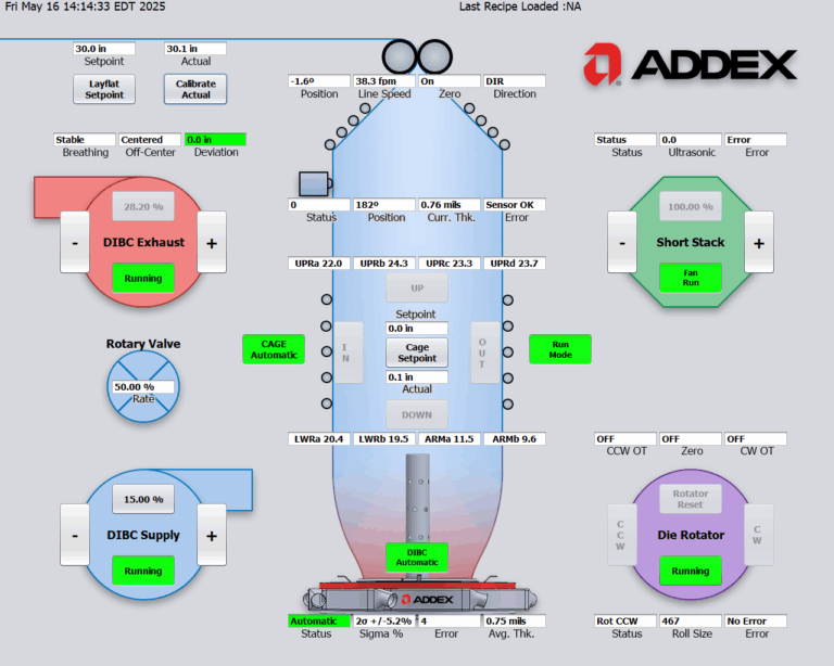
The sensor observes the tubular product directly and does not need to mathematically separate two superimposed layflat walls.
Current redesigned EGC systems use 100 through 364 radial-vane control zones across nominal 6- through 48-inch sizes. Final sizing uses the exact factory table, rounds up to the next listed 2-inch nominal size, and includes a job-built single-inlet plenum.[1]
Addex publishes EGC configurations for stationary, oscillating, and rotating dies, with mapper inputs for motion and nip speed.
EGC can be combined with Intensive Cooling, Digital IBC, cage control, inflation and deflation functions, and the wider Addex control architecture.
Addex offers several thickness-sensor options and places its around-bubble scanner between the highest frost line and the collapsing frame. The Rev. 8/2025 public literature remains useful for sensor arrangements and mapping details that were not superseded by the August 2026 factory notice, including light-contact capacitance, air-cushioned capacitance, air-cushioned nuclear, and air-cushioned X-ray options. Sensor selection should be made from film chemistry, gauge range, bubble behavior, required noncontact performance, calibration practice, and plant preferences rather than from one preferred method for every line.[2]
Addex publishes a greater-than-50-percent reduction in thickness variation for EGC. That is a manufacturer claim, not a universal result. Baseline die condition, existing variation, sensor quality, bubble stability, mapping, film structure, line speed, cooling capacity, and operating discipline determine the actual improvement.[1]
For lines where automatic control is not justified, Addex Manual Gauge Control can provide selective cooling adjustment without a fully automatic profile loop. The Blown Film Air Ring Selector helps screen EGC, MGC, Intensive Cooling, and related Addex options.
When post-layflat X-ray measurement is the stronger fit
Scantech measures the collapsed film on a flat web, then uses specialized algorithms and known die or haul-off rotation or oscillation to deconvolve the double layer and map the reconstructed profile back to the air ring or die. The architecture can be installed on a horizontal or vertical passline and can communicate mapped profile corrections to an Addex or other compatible control system.


Scantech publishes one blown-film profile approximately every 30 seconds for its post-layflat architecture.[3]
The flat web creates a practical source-and-detector geometry with high photon throughput and no sealed radioactive isotope source.
Scantech lists thickness plus filler measurements for calcium carbonate, titanium dioxide, and barium sulfate on blown-film applications.
Scantech can send the mapped profile to an Addex or other compatible air-ring or die control system while retaining flat and polar views, winder reports, trends, and traceability.
Horizontal ULO3 or vertical LH3?
Best when the line has a suitable horizontal span after collapse. The installation must also receive valid die or haul-off rotation or oscillation data so the two-layer signal can be reconstructed and mapped.
Best when the available straight passline is vertical or floor space is limited. The same two-layer X-ray and polar-profile concept is applied while the web travels vertically, provided known rotation or oscillation supplies the angular diversity required for reconstruction.
Web width, film construction, additives, line motion, guarding, passline, service access, and control objective determine the final frame and sensor configuration.
Scantech states that its double-layer separation is completed quickly enough to map the profile and support fast control actions. The company also publishes a complete profile approximately every 30 seconds. That rate is meaningful, but it is measurement-system performance, not a guarantee that the air ring, die, film, and full process will reach a new stable profile in the same time.[3]
Scantech can send the mapped thickness profile back to an Addex or other compatible air-ring or die control system. Its current blown-film literature describes Process Hub and I/O integration, control boxes for mechanically actuated air rings, and OPC UA as part of the system architecture. The application review must define the interface, mapping ownership, zone count, command limits, handshakes, and fail-safe behavior before commissioning.[3]
Use the Film and Sheet Measurement Systems page for the broader Scantech architecture, or review the web gauging technology guide when the project also includes cast film, sheet, coating, density, basis weight, or other web measurements.
Build a preliminary blown-film thickness measurement path
This selector identifies a reasonable starting architecture. Scantech post-layflat paths are available only when the die or haul-off rotates or oscillates. The result does not replace line drawings, sample testing, sensor review, mapping analysis, control-interface review, or a final Addex and Scantech application study.
Estimate transport and observation time
Use actual line geometry to see why scanner speed alone cannot predict closed-loop response. The calculator adds material transport, the selected number of profile periods, and an estimated actuator-plus-process settling time.
Important: This is a transparent planning model, not a control-system simulation. Some activities overlap, predictive control can compensate for known delay, rotating equipment changes path and mapping, and the actual actuator response may dominate the result. Use synchronized step-test data for final tuning.
When two measurement layers can be justified
Around-bubble and post-layflat measurement are not always competitors. They can answer different questions on the same high-value line.
Measure one wall close to the bubble and use EGC to correct repeatable circumferential cooling variation.
When rotation or oscillation is available, measure the collapsed web, reconstruct the polar profile, create roll records, and optionally send mapped corrections to Addex or another compatible control system.
Compare the two locations to separate die and cooling effects from collapse, transport, tension, or winding effects.
Two scanners increase capital, calibration, maintenance, integration, and interpretation burden. Define the risk that the second station will actually reduce.
A two-layer architecture makes the most sense when a film has high material value, demanding customer release records, critical filler or barrier behavior, difficult line motion, expensive off-spec production, or a history of disagreement between bubble profile and finished rolls. The Scantech layer still requires known rotation or oscillation. The project must also define whether Addex uses its own bubble measurement for EGC, receives Scantech mapped profile commands, or remains a separate verification layer. It is rarely the first recommendation for a straightforward commodity line that needs one reliable control signal.
Common blown-film thickness measurement mistakes
Choosing from scan speed alone
Profile rate matters, but the correction also includes material transport, deconvolution or mapping, actuator response, process settling, filtering, and the number of profiles required before another command is trusted.
Assuming the closest sensor is automatically the most accurate
Proximity reduces transport delay. Accuracy still depends on sensor physics, calibration, material, bubble stability, working condition, ring motion, profile filtering, and angular mapping.
Calling X-ray thickness a composition-independent direct measurement
X-ray attenuation depends on photon energy and material composition. The system converts attenuation to thickness through calibration and, where applicable, density or composition information. Fillers can be a useful measured signal or a source of bias when they change unexpectedly.
Specifying post-layflat polar control on a fully stationary line
A layflat scanner sees two walls at once. The reconstruction needs known die or haul-off rotation or oscillation so different wall sectors overlap over successive scans. If nothing rotates or oscillates, the system cannot uniquely separate the two walls into a circumferential profile for mapped control.
Using one scanner to explain every roll defect
Hard bands, telescoping, wrinkles, edge defects, blocking, and roll hardness can involve web tension, winding, collapse, guiding, temperature, or surface treatment even when the thickness profile is acceptable.
Mapping a profile without measuring the real transport path
Use material path length, actual web speed, haul-off position, die rotation, oscillation, and time-stamped data. Straight-line machine distance is not enough when the web passes around rolls or the path changes with motion.
Installing the scanner where service access is poor
A technically valid span can still be a bad installation if the frame blocks threading, cleaning, guards, nip access, maintenance, crane travel, operator sight lines, or emergency egress.
Promising Cpk, scrap, or resin savings before establishing the baseline
Measurement can reveal and reduce avoidable variation only when the process has a controllable cause and a usable actuator. Build the business case from current profile variation, average over-gauge, startup time, product mix, and the actual response achieved in trials.
Skipping offline correlation and roll-level verification
Define how online profiles correlate with conditioned samples, roll reports, customer methods, and the applicable ASTM, ISO, or internal procedure. A stable display is not a substitute for method validation.
Information needed to select the measurement location correctly
- Film structures and gauge rangeMinimum, normal, and maximum thickness; layers; resin families; density; color; fillers; barrier materials; and reclaim.
- Die and bubble geometryDie diameter, blow-up ratio, highest and normal frost line, bubble diameter, cage, collapsers, tower height, and access around the bubble.
- Line motionRotating die or oscillating or rotating haul-off, motion range, direction, speed, home position, nip speed, product speed, and changing material path. A fully stationary line is not eligible for Scantech post-layflat polar reconstruction.
- Available passlinesHorizontal and vertical straight spans, web width, roll locations, wrap, tension, threading, guards, service access, and scanner parking space.
- Control objectiveManual correction, EGC cooling control, die control, monitoring only, product reporting, filler measurement, or independent verification.
- Existing equipment and control interfaceCurrent scanner, Addex or other air ring, die control, IBC, cage, haul-off, winding, PLC, HMI, OPC UA, Process Hub, I/O, recipes, encoders, and plant network.
- Timing baselineDistance from actuator to sensor, line speed, current profile period, startup time, measured step response, and settling time.
- Quality and business baselineCD and MD variation, average over-gauge, off-spec rolls, startup scrap, changeover frequency, customer limits, and current Cpk or Ppk where valid.
- Offline reference methodSampling pattern, conditioning, mechanical gauge method, calibration standards, roll identification, and online-to-lab correlation.
- Representative dataPolar and flat profiles, trend files, line drawings, photos, difficult recipes, known thick bands, and examples of good and rejected rolls.
Related Gauge Advisor resources
Blown film thickness measurement FAQs
Is around-the-bubble measurement less accurate than post-layflat X-ray?
Not as a universal rule. Around-bubble accuracy depends on the selected sensor, calibration, material, working condition, bubble stability, contact or air-cushion behavior, and ring mechanics. Post-layflat X-ray offers strong transmission measurement on a stable flat web, but its thickness result still depends on calibration and its polar profile depends on deconvolution and mapping.
Is post-layflat measurement always faster?
Scantech publishes a complete profile approximately every 30 seconds, which can be faster than many bubble-scanning arrangements. The complete control response also includes transport, reconstruction, actuator response, film cooling, and settling. Faster measurement does not remove those other delays.
Can Scantech measure blown film on a vertical passline?
Yes. The LH3 is the vertical blown-film path, while the ULO3 is used on a horizontal passline. The correct frame depends on the actual web path, width, access, guarding, service requirements, and the required rotation or oscillation.
Can Scantech post-layflat measurement work if nothing rotates or oscillates?
Not for a deconvoluted polar profile. With a stationary die and stationary haul-off, each layflat position continues to combine the same two opposite bubble sectors. The scanner can still see the combined two-wall signal, but it cannot uniquely separate the walls and map a circumferential profile back to the air ring or die. Around-the-bubble measurement is the practical profile-control path on a fully stationary line.
Can Scantech send profile corrections to an Addex air ring?
Yes, subject to interface and application review. Scantech can map the reconstructed profile and communicate control information to an Addex or other compatible air-ring or die system. The project must define the motion inputs, zone map, Process Hub or I/O interface, command limits, controller ownership, alarms, and invalid-data behavior.
Can Addex use a sensor after the nip?
Addex literature lists after-primary-nip sensor options for compatible line arrangements and states that an oscillating haul-off is required. The current datasheet notes that this path is not available for rotating dies, so around-bubble measurement is often the relevant Addex route on rotating-die lines.
Why does a layflat scanner need deconvolution?
The collapsed web contains two superimposed bubble walls. A cross-web measurement is therefore a combination of two original circumferential locations. Multiple scans, motion and path information, and a mathematical model are used to estimate the separate polar profile.
Does X-ray measure true thickness directly?
The direct physical signal is photon attenuation. The control system converts that signal to a thickness or mass-related result using calibration and material information. Changes in density, composition, or high-atomic-number filler can affect the relationship.
Which system is better for rotating dies?
Addex publishes around-bubble EGC support for rotating dies and uses motion information for automatic mapping. Scantech can also reconstruct and map the post-layflat profile because the rotation provides the angular diversity the algorithm requires. The line geometry, measurement objective, transport delay, desired actuator, and control-interface architecture decide the better starting point.
When would I install both Addex and Scantech?
Consider two layers when close-to-actuator control and independent final-state verification address separate high-value risks, such as expensive multilayer film, demanding roll records, filler measurement, recurring disagreement between bubble and finished-roll profiles, or complex downstream behavior. Do not duplicate systems without a defined purpose.
Can either scanner correct machine-direction thickness variation?
A circumferential profile loop primarily addresses cross-direction or polar variation. Machine-direction variation can originate in gravimetric feed, extruder output, melt temperature, line speed, bubble diameter, IBC, cooling, and other time-based variables. Use the signal and actuator that address the actual cause.
How should the online system be validated?
Define the material recipes, gauge range, reference method, sample conditioning, cross-web and roll sampling pattern, calibration checks, mapping study, step response, alarm logic, data retention, and correlation to the customer or internal release method.
References and source notes
The references remain collapsible so the focused article stays readable. They open automatically when printing.
Open technical references and source notes12 sources
Gauge Advisor is the authorized Addex and Scantech sales and applications support partner. Addex and Scantech sources are used for current product architecture and manufacturer-published capability. Neutral research, NIST, ASTM, ISO, SPE, and resin-industry sources are used for measurement physics, control delay, film processing, and laboratory-method context. No competitive equipment manufacturer is cited.
- Addex, External Gauge Control. Public source for the EGC operating principle, controller mapping, sensor options, placement, and manufacturer performance claim. The current 100-through-364 radial-vane zone range, 6- through 48-inch nominal family, 2-inch size increments, round-up rule, and job-built single-inlet plenum architecture reflect Addex factory engineering specification supplied August 2026; revised public literature is pending.
- Addex, EGC Product Data Sheet, Rev. 8/2025. Historical public literature retained for sensor arrangements, rotating and stationary line compatibility, around-bubble and after-nip placement, mapper inputs, and the manufacturer-published one-degree profile-location mapping claim. Its former zone-count and multi-inlet plenum tables are superseded for new systems by the August 2026 factory specification.
- Scantech, Blown Film Measurements and Controls, Version 2025-10-A. Current manufacturer brochure covering double-layer separation, the required haul-off rotation or oscillation input, die or air-ring mapping, one-profile-per-30-second performance, OPC UA, horizontal or vertical passline options, and control integration through Process Hub and I/O or control boxes.
- Scantech, ULO3 Scanner. Current product-family page for the ULO3 scanner platform.
- Scantech, LH3 Scanner. Current product-family page for the LH3 scanner platform.
- Salo and Ritala, Blown Film Thickness Control with a Scanning Down-the-Line Measurement, 2022 American Control Conference. Peer-reviewed comparison of direct one-sided bubble measurement with two-layer flat-web measurement, transport delay, scanning delay, reconstruction, and control architecture.
- NIST, XCOM Photon Cross Sections Database. Authoritative photon-scattering and attenuation-coefficient context for elements, compounds, and mixtures.
- ASTM D6988-21. Guide for determining the thickness of plastic-film test specimens where thickness is used in property calculations or required by a material or test specification.
- ISO 4593:1993. Mechanical-scanning method for plastic film and sheeting; the standard notes that the method is not suitable for embossed film or sheeting.
- LyondellBasell, How to Solve Blown Film Problems. Resin-industry troubleshooting reference for bubble behavior, gauge variation, collapse, winding, and related blown-film defects.
- SPE Extrusion Division, Blown Film Cooling Air Parameters. Technical context for the relationship among melt uniformity, die flow, cooling air, bubble stability, and film formation.
- Addex, Benefits of Auto-Profile Control Systems. Manufacturer discussion separating transverse-direction profile control from machine-direction control and explaining the intended role of repeated circumferential thickness profiles.
Choose the measurement location from the complete blown-film process
Gauge Advisor is the authorized Addex and Scantech sales and applications support partner. I help blown-film manufacturers evaluate around-the-bubble measurement, Addex EGC and MGC air rings, Intensive Cooling, Digital IBC, Scantech horizontal and vertical layflat X-ray scanners, mapping, controls, data, and retrofit requirements.
Gauge Advisor supports equipment selection and integration for the manufacturers represented here; independent process consulting is not offered. Send the line drawing, die size, bubble and passline geometry, film structures, gauge range, motion, current profiles, control objective, and representative process data when available. I will respond within one business day, often within a few hours.
- Bubble versus layflat architecture review
- Addex EGC, MGC, cooling, and IBC selection
- Scantech ULO3 horizontal or LH3 vertical passline review
- Motion, deconvolution, mapping, delay, and Addex or other control-interface requirements
- Line drawings, samples, and factory coordination
- Quotation, integration, and ongoing support