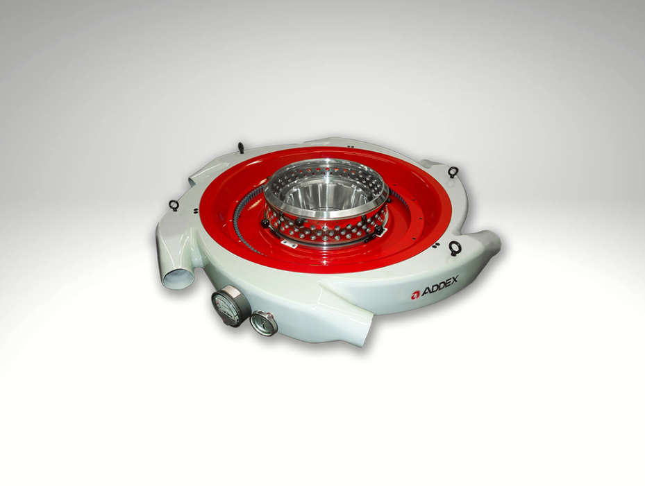
Blown Film Gauge Control to Reduce Thickness Variation
Repeatable thickness variation can increase resin giveaway, scrap, and winding problems. Gauge Advisor helps you evaluate Addex manual or automatic gauge control for your existing blown film line, starting with the profile pattern and the improvement you need.
Start with your die diameter, current gauge problem, and production goal. If available, a bubble photo and recent profile can support the follow-up review.
 Addex is the equipment manufacturer. Gauge Advisor provides authorized sales and applications support and welcomes Addex equipment project inquiries worldwide. I review the application and coordinate the appropriate manufacturer team for your location.
Correct recurring thickness variation at its source
Addex EGC uses a compatible online film-thickness profile to adjust the corresponding cooling zones around the bubble, accounting for die or haul-off movement.
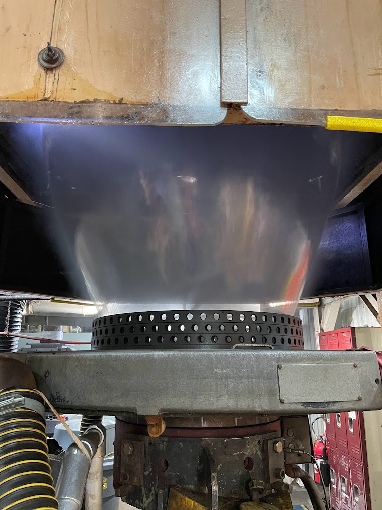
A difficult line returned to production with lower reported scrap
Addex reports that a Crayex line had lost operator confidence and certain products were difficult to schedule. After the EGC installation and learning period, the customer reported substantially lower scrap and wanted the technology considered for additional lines.
Is automatic gauge control right for your line?
MGC and EGC work best on repeatable circumferential total film variation. Random instability, average thickness drift and one-layer defects need a different first response.
Fixed bands
Thick or thin areas remain tied to the same die position through consecutive profiles.
MGC or EGC candidateMoving bands
The pattern moves with a rotating die, oscillating haul off or another known coordinate.
Mapped EGC reviewRandom variation
The profile changes without a repeatable angular source or stable consecutive pattern.
Stabilize the process firstAverage thickness drift
The complete profile moves above or below target as output or haul off conditions change.
Review average gauge controlLayer-specific variation
Total film may look acceptable while one coextruded layer varies independently.
EGC cannot isolate one layerStart with the thickness variation you need to reduce
Choose the profile pattern, line movement, measurement, cooling and bubble requirements. The selector helps separate an MGC or EGC project from an air ring, IBC, BIDS or complete retrofit plan.
Compare manual adjustment with automatic thickness correction
The air ring provides external cooling. MGC adds manual adjustment of thickness around the bubble, while EGC adjusts it automatically on a compatible Addex system.
MGC / icMGC
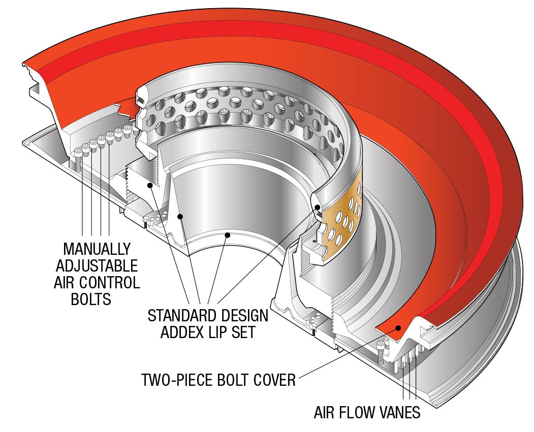
Use MGC when the total film profile has repeatable fixed bands and periodic operator optimization is acceptable. Local mechanical adjustments change airflow around the circumference without an automatic profile loop.
Request an MGC review →Two stepper motors
EGC / icEGC
Use EGC when a compatible online total film profile can be mapped to a stable bubble and automatic localized cooling correction is justified by resin, quality or operator workload.
Review current EGC sizing →| Decision | MGC | EGC |
|---|---|---|
| Best starting fit | Repeatable fixed profile with acceptable manual adjustment | Repeatable profile requiring automatic mapped correction |
| Profile measurement | Useful for setup and verification | Compatible online total film profile required |
| Correction action | Operator changes localized airflow settings | Two stepper motor assemblies position the correction mechanism |
| Moving line | Manual relationship must remain understandable | Reviewed position feedback and coordinate mapping required |
| Operator role | Interpret the profile and make periodic adjustments | Stabilize, verify, enable automatic control and recover from upsets |
Measure film thickness and adjust the corresponding cooling zones
The correction loop depends on a valid profile, stable process, correct transport delay and accurate movement information. EGC cannot correct a location it cannot reliably identify.
Build the profile
A compatible scanner measures total film thickness around the flattened web.
Relate time to distance
Line speed and transport distance connect the measured film with when it left the bubble.
Find the source angle
Gen3 applies the die and haul off position needed to locate the responsible radial coordinate.
Change local cooling
The two motorized assemblies position the EGC correction mechanism across the radial vanes.
Review the next profiles
The loop checks whether stable consecutive profiles improve without destabilizing the process.
How the radial vanes and two-motor correction mechanism work
Many radial vanes, two stepper motors
Current EGC distributes localized cooling through 100 to 364 physical radial vanes, depending on die size. Two stepper motor assemblies coordinate the complete correction mechanism. This concentrates actuation in serviceable assemblies while preserving dense circumferential airflow control.
Single-inlet plenums and the current 100 to 364 vane guide
The redesigned EGC is optimized for manufacturability from higher-quality plate material. Current new-build plenums use a job-specific single inlet and are built in 2-inch diameter increments, like lip sets.
View current EGC vane counts and single-inlet plenum details
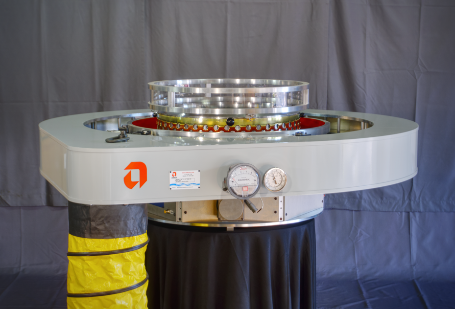
One external inlet, built for the job
The current single-inlet direction reduces external hose clutter and keeps the plenum, lip set, airflow and service access inside one reviewed factory configuration.
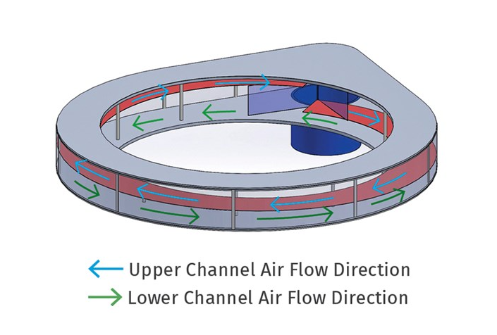
Opposing internal flow paths
The plenum distributes air around the ring through opposing paths before it reaches the selected radial vanes and lip arrangement.
Current EGC factory planning guide
This is the current new-build sizing guide supplied by Addex. Final air ring, radial vanes, plenum, lip set, blower, profiler, movement feedback, controls and performance follow the written quotation.
| Die Ø, in. | Die Ø, mm | Radial vanes |
|---|---|---|
| 6 | 150 | 100 |
| 8 | 200 | 114 |
| 10 | 250 | 126 |
| 12 | 300 | 144 |
| 14 | 360 | 152 |
| 16 | 410 | 170 |
| 18 | 460 | 180 |
| 20 | 510 | 192 |
| 22 | 560 | 216 |
| 24 | 610 | 224 |
| 26 | 660 | 238 |
| Die Ø, in. | Die Ø, mm | Radial vanes |
|---|---|---|
| 28 | 710 | 256 |
| 30 | 760 | 272 |
| 32 | 810 | 288 |
| 34 | 860 | 288 |
| 36 | 910 | 300 |
| 38 | 970 | 300 |
| 40 | 1020 | 308 |
| 42 | 1070 | 330 |
| 44 | 1120 | 336 |
| 46 | 1170 | 338 |
| 48 | 1220 | 364 |

Map rotating dies and oscillating haul offs separately
A scanner sees the flattened web after transport delay and downstream movement. Gen3 must reconstruct where that film originated at the air ring before EGC can apply correction to the correct radial location.
Review movement signals and one-degree mapping
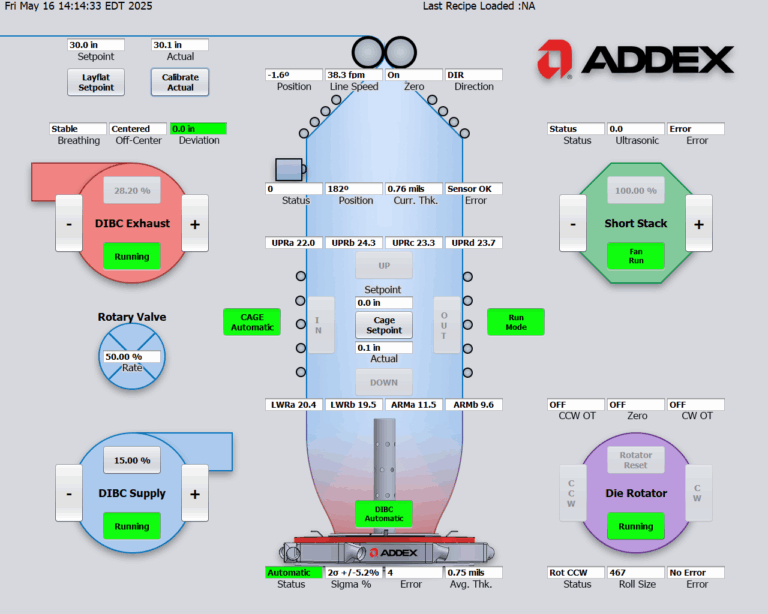
Let operators verify the process before EGC acts on it
The value of automatic correction depends on clear operating procedures. Operators first stabilize the line and validate the profile, then enable correction when the measurement and movement signals are trustworthy.
Define the complete gauge control loop before ordering hardware
Plan the air ring, airflow, thickness measurement, movement signals and controls together. Agree on commissioning and performance checks, and confirm which existing equipment is suitable for reuse.
Modernize the verified constraint
Document the installed air ring, plenum, profiler, movement hardware, controls and profile loss before deciding what can remain.
- Model, serial number, controls generation and drawings
- Air ring, lip set, plenum, blower and duct condition
- Scanner, profile format, line speed and transport distance
- Die and haul off motion signals, zero and direction
Protect interfaces before layout freezes
Coordinate mechanical, airflow, electrical and measurement responsibilities early enough to avoid a controls package built around missing signals.
- Confirm die size, product range and current vane guide
- Assign blower, ducting and single-inlet plenum scope
- Define profiler, encoder, I/O and interlocks
- Agree on commissioning products and acceptance evidence
Die and movement
Die diameter, lip set, BUR, frost line, cage, tower, scanner location and every rotating or oscillating component.
Normal and difficult film
Resin, structure, thickness, output, width, properties, current profiles and the products that justify correction.
Ring, blower and ducts
Installed hardware, nameplates, curves, filters, duct sizes, inlet arrangement, photographs and maintenance condition.
Profiles and losses
Consecutive stable profiles, scrap, overbuild, intervention frequency, movement trends and the target business result.
Request an Addex MGC or EGC application review
Send the die, air ring and airflow equipment, consecutive profiles, online measurement, line movement, product range, current losses and the result the plant needs to improve. Gauge Advisor will organize the application for Addex review and quotation.