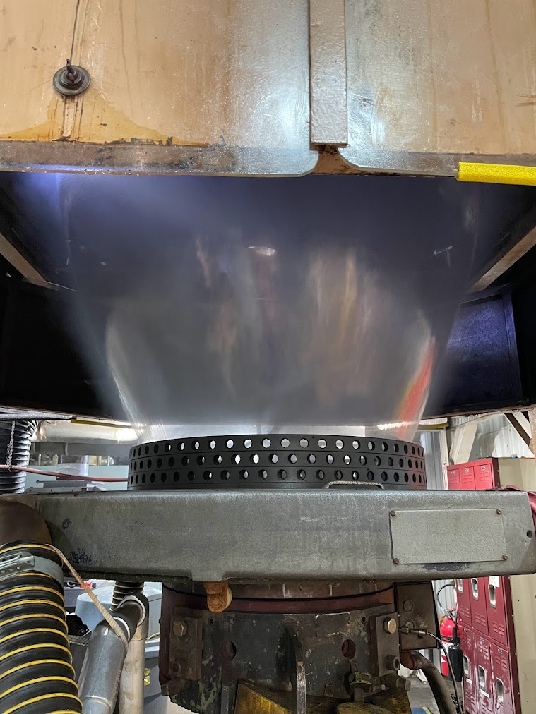
Digital Internal Bubble Cooling and Layflat Control
Addex Digital Internal Bubble Cooling (DIBC) controls compatible supply and exhaust airflow to maintain bubble size and layflat width, the width of the flattened film tube. Multiple sensors and temperature compensation help the controller coordinate the selected blowers or valves on new lines and retrofits.
 Addex is the equipment manufacturer. Gauge Advisor provides authorized sales and applications support and welcomes Addex equipment project inquiries worldwide. I review the application and coordinate the appropriate manufacturer team for your location.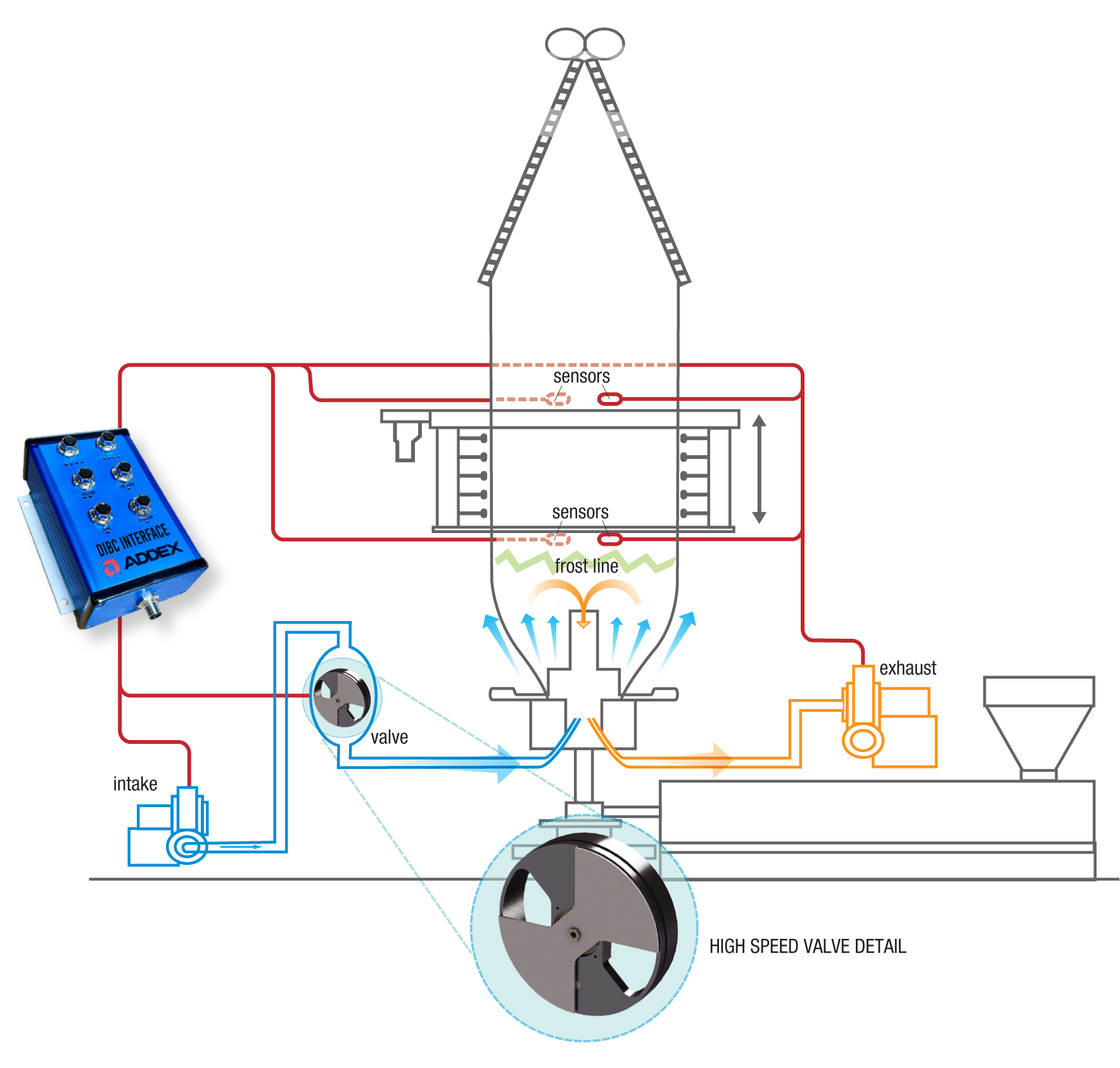
Control the internal air path, not just one blower
The right configuration depends on the internal bubble cooling (IBC) passage, supply and exhaust equipment, sensors, film format, required response and existing line controls.
Why is the plant reviewing IBC control?
DIBC is most useful when the line has a suitable IBC airflow system but operators still need to make frequent adjustments to bubble size or layflat width, especially during product changes.
Layflat drift
Bubble diameter changes during production and finished width moves outside the desired window.
Closed loop layflat objectiveManual airflow chasing
Operators repeatedly balance internal supply, exhaust or valve position to hold size.
Coordinated internal responseSlow width changes
Product changes consume excessive time and transition scrap while the bubble is resized.
Recipe and response reviewRetain useful IBC hardware
The physical internal air path may remain useful but the controls lack modern feedback.
Compatibility and condition reviewCoordinate the tower
IBC, cage position, air ring and saved setups need clearer operator displays and controls.
Gen3 and Cage Control systemCompare DIBC, BIDS and other control options
Describe the existing bubble-air system, target layflat width, width changes and any related thickness-control or bubble-cage needs. The selector suggests equipment options for Addex to review.

Separate IBC hardware from Digital IBC control
Internal Bubble Cooling begins with a usable passage through the die, supply and exhaust airflow, ducting and devices that can change the internal air balance. DIBC measures bubble response and commands compatible devices. Software alone cannot create IBC capacity.
- Confirm the die and internal cooling passage.
- Document supply and exhaust blowers, ducts, filters and valves.
- Verify sensor clearances and stable bubble visibility.
- Review drive authority, I/O, interlocks and retained controls.
- Check condition, serviceability and available airflow range.
Moves cooling air through the bubble
Die internals, supply and exhaust paths, blowers, ducts and applicable valves provide the mechanical airflow capacity.
Measures and coordinates the response
Multi-sensor bubble feedback, temperature compensation, target layflat, controller logic and the configured actuators close the loop.
Measure bubble size, compare it with the target and rebalance internal airflow
The exact device response depends on the selected DIBC configuration. The control objective remains the same: keep the measured bubble diameter and resulting layflat near the operator's target.
Enter layflat
The operator selects the required product width or recalls an approved recipe.
Measure bubble
Multi-sensor feedback observes the bubble at upper and lower cage elevations.
Calculate error
Gen3 compares the measured diameter with the target using temperature-aware calibration.
Adjust internal air
The configured supply, exhaust and applicable valve devices rebalance the bubble.
Hold and monitor
The loop continues while the operator monitors frost line, stability and the complete process.
Coordinate supply and exhaust drives
Variable-speed control adjusts airflow through the selected blower configuration. Suitability depends on response, turndown, pressure, flow and the product range.
- Confirm motor and drive compatibility
- Review usable blower turndown
- Document supply and exhaust authority
Add faster airflow response when the application requires it
Some DIBC configurations combine a high-speed valve with the blowers to support faster transitions. Addex confirms whether this option fits the line and the required response.
- Define the width-change objective
- Confirm film format and valve path
- Use the written Addex configuration

How the sensors track changes in bubble size
Addex DIBC uses multi-sensor feedback at upper and lower cage elevations with temperature compensation. Final sensor quantity, mounting, field of view and geometry follow the line and the written project design.
- Keep the sensor’s measurement path to the bubble clear.
- Review frost line range, cage motion and tower clearance.
- Protect sensors from heat, contamination and mechanical interference.
- Confirm the bubble surface can be measured across the product window.
- Plan calibration and verification after mechanical changes.
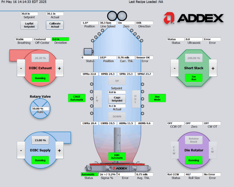
Give operators clear steps from setup to automatic control
The operator still owns extrusion conditions and safe production. DIBC reduces repetitive internal-air adjustments after the process is stable and the required control mode is enabled.
Keep layflat control separate from gauge profile, external cooling and cage position
Gen3 can coordinate quoted modules, but the equipment components still solve distinct physical problems.
DIBC
Controls compatible active internal supply and exhaust airflow to maintain bubble diameter and layflat.
See the control loop ↑BIDS
Inflates or deflates contained bubble air on a compatible non IBC line.
Review BIDS →External air ring
Cools the outside of the bubble and supports near-die stability.
Review air rings →MGC or EGC
Changes localized external cooling to correct repeatable circumferential total film profile.
Review gauge control →Cage Control
Positions the physical cage around the changing bubble. It does not replace DIBC bubble-air control.
Review coordinated retrofits →Retain compatible equipment only after condition and interface review
Addex can evaluate existing IBC equipment for reuse. The internal passages, blowers, valves, drives, sensors and controls must be in suitable condition and provide the airflow and adjustment range the project requires.
Modernize the feedback and response
Document the installed air path and determine which mechanical and electrical components can remain.
- Model, serial, drawings and equipment photographs
- Supply and exhaust blower curves and drives
- Valve path, sensor layout and control authority
- Current layflat behavior and difficult changes
Protect the internal air path before layout freezes
Coordinate die internals, supply and exhaust sizing, ducts, valves, sensors, cage, tower, controls and service access early.
- Define product and width-change range
- Assign airflow and controls responsibilities
- Plan sensor clearance and cage movement
- Agree on commissioning and acceptance products
Document the air path
Capture die internals, blowers, ducts, valves, sensors, cage, tower, controls and the current loss.
Approve interfaces
Identify the equipment to reuse or supply, the required drive adjustments, input/output connections, interlocks and responsibilities.
Prepare the shutdown
Plan mechanical, electrical, sensor, network and safe-start work before equipment arrives.
Calibrate and tune
Verify bubble measurement, temperature compensation, response, recipes, alarms and manual recovery.
Run agreed products
Confirm stable layflat behavior, operator training, recovery checks and support readiness.
Share the existing IBC equipment, product range and layflat problem
You do not need to choose a control configuration first. Share line details and operating examples so Addex can evaluate the available airflow adjustment, sensor locations and required response.
Die, supply and exhaust
Die and IBC design, blower curves, drives, ducts, filters, valves, nameplates, drawings and photographs.
Bubble, cage and tower
Layflat and BUR range, frost line, cage, tower, sensor locations, collapsing frame and clearance.
Normal and difficult recipes
Resin, structure, thickness, output, film format, width range, properties and typical process settings.
Drift and width-change evidence
Actual layflat trends, changeover time and scrap, manual adjustments, alarms and the target operating result.
Continue with the page that matches the next control decision
Explore related options for bubble-size control, external cooling, thickness control, retrofit planning and return on investment.
Request an Addex Digital IBC review
Send the installed IBC hardware, supply and exhaust equipment, bubble and tower geometry, product and width range, current layflat behavior, changeover evidence, controls and the result the plant needs to improve. Gauge Advisor will organize the application for Addex review and quotation.