Addex blown film retrofit systems

Upgrade the Blown Film Line You Already Own

Keep the equipment that still performs. Upgrade the constraint that limits saleable output, gauge profile, layflat, changeovers or operator consistency. Then coordinate the required cooling, bubble and control layers through one practical retrofit plan.

RetainUseful mechanical investment
ModernizeThe active process constraint
CoordinateCooling, gauge and bubble control
Addex blown film cooling and control equipment logoAddex is the equipment manufacturer. Gauge Advisor provides authorized Addex sales, application review and quotation support for retrofit projects across the Western U.S. and Canada.
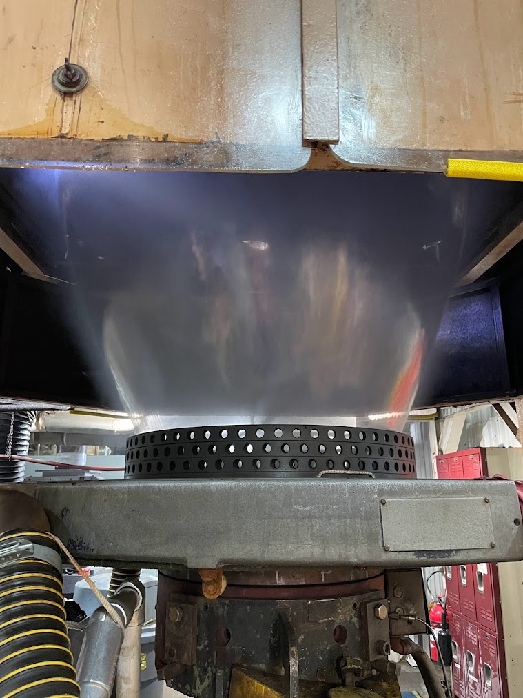
Operating blown film bubble evaluated for cooling and controls retrofits
Upgrade the bottleneck, not the entire line

Start with the production loss

An air ring, EGC, IBC control, cage system or controls upgrade should solve a verified problem on the installed line. The line survey determines what stays, what changes and what must work together.

What the animation shows: the separate cooling, gauge profile, bubble, cage and movement layers that can be coordinated on an existing blown film line. A real retrofit may use one layer or several. Final equipment and control scope requires Addex application review.

Where retrofit value usually hides

What is the installed line losing today?

The strongest retrofit begins with a measurable production loss, not an equipment acronym. Identify the first signal that changes when the line becomes difficult to run.

01

Cooling margin

Frost line rises, film stays hot or the bubble becomes unstable as output increases.

Air ring and cooling review
02

Gauge profile

Repeatable thick and thin bands force resin overbuild, roll segregation or quality holds.

MGC or EGC review
03

Bubble and layflat

Diameter drifts or operators continually chase internal supply and exhaust airflow.

DIBC or BIDS review
04

Changeover time

Width changes consume excessive minutes and transition scrap across multiple manual adjustments.

Recipes and coordinated control
05

Shift consistency

Results depend too heavily on one experienced operator or undocumented setup knowledge.

Gen3 and cage automation
Important diagnostic boundary: unstable melt pressure, damaged die hardware, random variation, dirty air paths, building drafts or downstream limitations may require a different first action. Use the blown film bottleneck guide before assuming the air ring is the root cause.
Survey before scope

Treat the line as an installed system, not a blank sheet

Die size alone cannot define a retrofit. Product range, output, tower geometry, air delivery, IBC hardware, movement, measurement, controls and downstream capacity determine which equipment can be retained and which interfaces need to change.

Complete blown film extrusion line reviewed for retrofit opportunities
Build the evidence around normal and difficult products

Map the current line before selecting the upgrade

A useful survey follows the process from the die to the nip and records what moves, what measures, what controls airflow and where the current loss first becomes visible.

  • Document die diameter, lip geometry, blow up ratio and frost line range.
  • Record blowers, ducts, filters, valves, IBC supply and exhaust paths.
  • Confirm whether the die, haul off or both rotate or oscillate.
  • Locate the online profile measurement and calculate transport delay.
  • Review cage, collapsing frame, nip, haul off, winder and tower clearances.
  • Capture current PLC, HMI, drives, I/O, safety functions and network policy.
Retain

Keep what still works

Compatible mechanical equipment can remain when its condition, capacity and interfaces support the target result.

  • Useful IBC hardware
  • Suitable blower capacity
  • Valid profile measurement
Replace

Change the active constraint

Replace equipment that lacks airflow, correction authority, condition, clearance or control compatibility.

  • Air ring or plenum
  • Legacy controls
  • Inadequate sensors or drives
Coordinate

Connect interacting layers

Cooling, EGC, IBC, cage position and movement mapping may need one operating narrative even when some hardware remains.

  • Shared recipes and modes
  • Mapped position signals
  • Defined responsibility boundaries
A phased modernization path

Solve the verified constraint now and protect the next step

A retrofit does not have to replace every system at once. The first phase should produce measurable value while preserving a clean route to later controls or mechanical upgrades.

Now

Stabilize the loss

Correct the first verified problem with the smallest complete scope that can be commissioned and measured.

  • Restore cooling or airflow authority
  • Correct one profile or layflat problem
  • Establish baseline production data
Next

Coordinate the process

Add the measurement, movement or bubble control layer that reduces repeated manual intervention.

  • Integrate EGC profile feedback
  • Coordinate DIBC or BIDS
  • Add cage or movement tracking
Future

Standardize operation

Use shared recipes, histories, diagnostics and consistent operating modes to reduce dependence on tribal knowledge.

  • Modernize legacy controls
  • Expand the Gen3 architecture
  • Plan repeatable acceptance checks
Six common retrofit paths

Upgrade the part of the process operators keep chasing

These layers solve different problems. The line may need only one, or several may need to share feedback and recipes through Gen3.

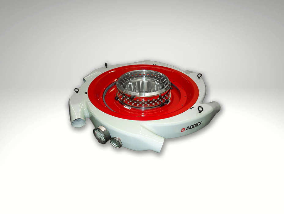
Addex blown film air ring for retrofit cooling
External cooling

Air ring and cooling retrofit

Review the base air ring, lip set, plenum, blower, ducting and tower around output, frost line and bubble stability. Intensive Cooling or a separately engineered Short Stack path may be considered when cooling is the verified limit.

Explore Addex blown film air rings →
EGCGauge profile
Manual or automatic correction

Gauge profile retrofit

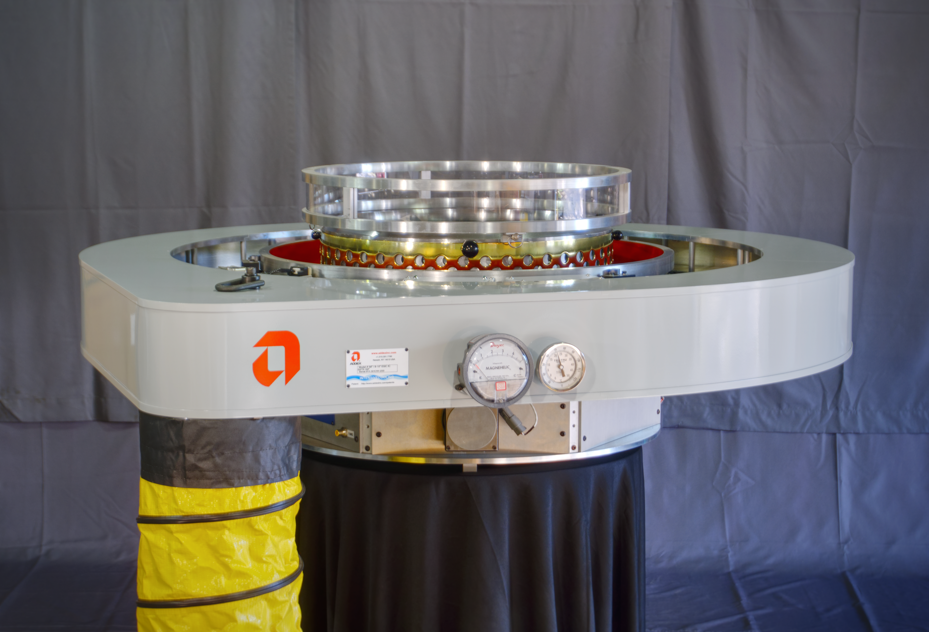
MGC adds local manual airflow adjustment for repeatable fixed bands. EGC adds mapped automatic correction using a valid online total film profile. Moving dies and haul offs require accurate coordinate tracking.

Compare MGC and EGC →
IBCActive internal air
Compatible IBC line

Digital IBC and layflat retrofit

DIBC coordinates compatible internal supply and exhaust airflow using multi sensor bubble feedback. Existing IBC hardware may be retained when condition, geometry and control authority support the required response.

Explore Digital IBC and layflat control →
BIDSNon IBC layflat
Retained air bubble

Automatic layflat control without IBC

On a compatible non IBC line, BIDS can automate inflation and deflation of the contained bubble air to maintain the operator's layflat target. It does not add internal cooling or replace EGC gauge profile control.

Explore automatic non IBC layflat control →
CAGEPhysical position
Bubble support

Automatic cage positioning

Cage Control positions the physical cage around the changing bubble. It can complement DIBC or BIDS, but it remains a separate mechanical control layer with its own clearances and motion requirements.

Discuss cage automation →
GEN3Common workflow
Controls modernization

Gen2 to Gen3 and coordinated controls

Gen3 hosts the quoted Addex modules through one interface for modes, recipes, histories, alarms and diagnostics. Installed controls generation, retained devices and communication boundaries require serial number and drawing review.

Request an installed base review →
Current EGC and moving line modernization

Map the correction to the real line, even when equipment moves

The new EGC direction uses job built single inlet plenums in two inch diameter increments and current radial vane sizing. Installed multi inlet equipment and earlier Gen3 systems remain valid retrofit context, but they must be verified by model, serial number, drawings and controls generation.

Current Addex single inlet plenum for a blown film EGC retrofit
Current new project direction

Job built Single Inlet Plenum

One external air connection simplifies the hose arrangement while internal distribution is engineered around the selected die size, lip set and EGC architecture.

  • Current EGC planning range: 6 to 48 inch dies
  • Current planning range: 100 to 364 radial vanes
  • Round up when the die falls between listed sizes
  • Final configuration follows the written Addex scope
Addex controller for rotating die or oscillating haul off mapping
Rotating die or oscillating haul off

Movement aware gauge correction

The controller must relate the incoming total film profile to the correct radial correction zone while the die, upper haul off or both move.

  • Capture each moving component separately
  • Confirm position, speed, direction and zero
  • Define scanner location and transport delay
  • Document modes, interlocks and recovery behavior
Measurement dependency: EGC requires a reliable online total film profile. Scanner physics, frame selection, HMI and profile records belong on the web gauging systems page. The measurement source and the Addex correction device are separate decisions.
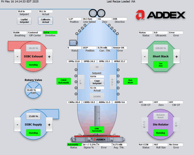
Addex Gen3 operator interface for coordinated blown film retrofit controls
Make the upgraded line easier to run

Give operators a controlled path from startup to automatic operation

The commercial value of controls modernization is not automation for its own sake. It is a repeatable workflow that lets the operator stabilize the process, verify the signal, enable correction and recover from an upset without treating the system like a black box.

OffsheetKeep automatic profile correction inactive while the process is down, changing or unstable.
Profile onlyMeasure the process and confirm that consecutive profiles are stable enough to act on.
AutomaticEnable mapped correction after the line, measurement and position signals are valid.
RecoverUse alarms, trends, manual controls and a uniform correction profile to return to a known state.
Time to saleable filmStartup and product change duration
Resin above targetAverage gauge and overbuild opportunity
Interventions per shiftManual airflow and cage adjustments
Recovery consistencyRecipes, alarms and repeatable restart checks
Reduce retrofit anxiety before the shutdown

Define the installation and acceptance path with the equipment scope

A successful retrofit needs mechanical, airflow, electrical and controls ownership to be clear before equipment arrives. Commissioning should verify mapping and operator recovery, not only that the hardware powers on.

01 / SURVEY

Document the line

Capture products, losses, geometry, airflow, movement, measurement, controls, utilities and existing equipment condition.

02 / ENGINEER

Approve the interfaces

Define retained hardware, supplied equipment, clearances, drawings, signals, interlocks and responsibility boundaries.

03 / INSTALL

Prepare the shutdown

Plan mechanical work, blower and duct changes, panels, drives, I/O, encoders, sensors, network access and safe startup.

04 / COMMISSION

Map and tune

Verify position, direction, transport distance, line speed, airflow authority, recipes, alarms and manual recovery.

05 / ACCEPT

Prove the result

Run agreed products and confirm stable operation, profile or layflat response, operator training and support readiness.

Project boundary: installation labor, commissioning duration, performance terms, acceptance criteria, training, service and responsibilities follow the written Addex quotation and approved project documents.
Addex External Gauge Control air ring used for automatic blown film gauge profile correction
Addex published application example

A difficult installed line returned to regular production

Addex reports that a Crayex line with persistent gauge variation had lost operator confidence and made wider products difficult to schedule. After the EGC retrofit and the initial learning period, the customer reported a substantial reduction in scrap.

18 to 22%Customer reported scrap before installation
6%Customer reported scrap after the learning period
Application specific result: this is an Addex published customer example, not a typical or guaranteed outcome. Current EGC vane sizing follows the latest factory planning guide, not legacy counts in the older case story.
Interactive Addex selector

Build a preliminary retrofit path around the current loss

Choose output, gauge profile, IBC, non IBC layflat, cage or coordinated controls. The selector organizes the equipment layers and carries the preliminary result into the contact form.

Preliminary only: the selector qualifies the application. Addex review confirms equipment, compatibility, performance terms, responsibilities and quotation.
What to send for a useful retrofit review

Start with one normal product, one difficult product and the installed line

You do not need to select the Addex model first. Send enough evidence to separate cooling, gauge profile, bubble, movement, measurement and downstream constraints.

01 / EQUIPMENT

Model, serial and drawings

Air ring, IBC, cage, blower, scanner, controls generation, nameplates, existing drawings and clear photographs.

02 / GEOMETRY

Die, tower and movement

Die diameter, air ring elevation, frost line range, tower clearance, cage, scanner location, rotating die and oscillating haul off.

03 / PRODUCTS

Normal and difficult recipes

Resin and structure, thickness, layflat, blow up ratio, output, film format, properties and current operating window.

04 / EVIDENCE

Profiles, trends and losses

Gauge profiles, roll reports, pressure and output trends, changeover records, scrap, operator observations and the target result.

Keep what works. Upgrade the constraint.

Request an Addex blown film line retrofit review

Send the installed equipment, die and movement arrangement, products, output, layflat, gauge profile, blower and IBC details, tower photos, control interfaces and the result the plant needs to improve. Gauge Advisor will organize the evidence for Addex application review.

Final scope boundary: selected equipment, drawings, compatibility, performance, installation, controls, commissioning, service, acceptance and responsibilities follow the written Addex quotation and approved project documents.
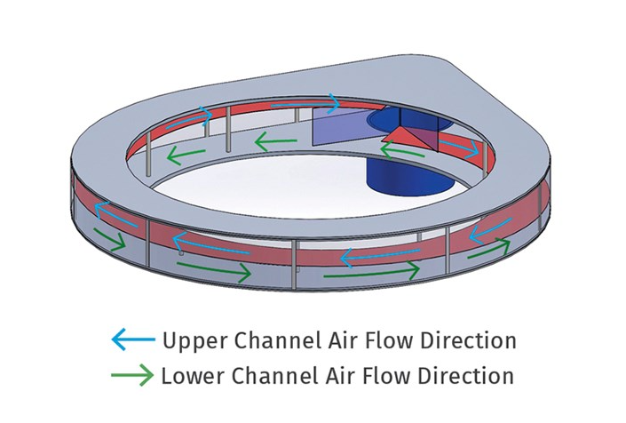
Addex single inlet plenum counterflow diagram for a blown film retrofit
Blown film retrofit FAQ

Questions before modernizing an existing line

What can be upgraded on an existing blown film line?
Potential retrofit layers include the external air ring and cooling package, manual or automatic gauge profile control, compatible IBC control, automatic non IBC layflat control, cage positioning, movement tracking and Gen3 controls. The useful scope depends on the installed equipment, products, active production loss and interface review.
Does a retrofit require replacing the complete air ring and IBC system?
Not always. Compatible mechanical equipment may be retained when its condition, capacity, geometry and controls interfaces support the required result. The survey should document what remains, what Addex supplies and who owns each mechanical and controls boundary.
Can a retrofit be completed in phases?
Yes. A plant may first solve a verified cooling, gauge profile or layflat constraint, then add coordinated measurement, movement, cage or controls functions later. Each phase should be complete enough to commission and measure, while preserving a clear path to the next upgrade.
What is the difference between DIBC and BIDS?
DIBC controls compatible active internal cooling supply and exhaust airflow on an IBC line. BIDS automatically inflates or deflates the retained bubble air on a compatible non IBC line to maintain layflat. Neither system replaces EGC when the problem is circumferential gauge profile.
Can Addex EGC work with a rotating die or oscillating haul off?
Potentially. A moving line requires position, speed, direction and zero information for each moving component, plus scanner location, line speed and transport delay. Addex review confirms the mapping architecture and whether existing movement hardware can be integrated or must change.
What information is needed for an installed Addex controls upgrade?
Provide the Addex model and serial number, controls generation, electrical drawings, HMI and panel photographs, connected modules, retained sensors and drives, network policy and the operating problem the upgrade should solve. Product family names alone are not enough to confirm installed hardware or software.
How should a plant evaluate retrofit payback?
Use the loss that actually appears in production: saleable output, resin overbuild, profile related scrap, width change minutes, transition pounds, manual interventions or downtime. The Gauge Advisor blown film ROI calculator lets the plant use its own assumptions rather than relying on a universal improvement claim.
What does Gauge Advisor do on an Addex retrofit project?
Gauge Advisor provides authorized Addex sales and applications support by defining the problem, collecting line and product data, organizing the preliminary architecture, coordinating factory review and supporting the commercial quotation. Final manufacturer configuration, performance terms, service and factory technical determinations belong to Addex and the written project scope.


Unlock more throughput. Coordinate the line.

Intensive Cooling can add 10–15% output on qualifying upgrades versus a conventional dual-flow baseline. Gen3 uses measured haul-off position and nip speed as inputs to circumferential film-profile mapping while coordinating cage control, EGC, die movement, and DIBC.

Addex blown-film measurement and control overview A Gauge Advisor overview reveals a running blown-film line with increased cooling-limited throughput as the primary outcome. The bubble visibly converges through the collapsing frame into counter-rotating haul-off nip rolls, then becomes a moving layflat web. Addex measures haul-off position and nip speed as inputs to its circumferential film-profile mapping algorithm; it does not control haul-off motion. The view continues through ultrasonic-guided bubble-cage positioning, a rotator or oscillator interface below the air ring, External Gauge Control using one-degree film-profile mapping with annular external cooling airflow, and Digital Internal Bubble Cooling using split ultrasonic sensing with two-sided intake, circular distribution, and center exhaust airflow. The flat web keeps moving through and visibly wraps a slowly rotating dual-station winder roll before the sequence ends with these measurement and control functions connected through the modular Addex Generation 3 control system. FLAT WEB TO WINDING GEN3 HAUL-OFF TRACKING POSITION + NIP SPEEDMAPPING INPUT GEN3 CAGE ULTRASONIC-GUIDEDPOSITIONING DIE ROTATOR / OSCILLATOR ADDEX / EGC INTAKE EXHAUST
Static overview

Interactive blown-film selector

Find the right air-ring or control path

Describe the goals, line architecture, process behavior, and control approach, then receive one layered Addex system path.

5 guided stepsUsually 2–3 minutes
Gauge Advisor interactive tool

Blown Film Air Ring & Control Selector