Updated August 21, 2026
Medical tubing measurement validation is not the same thing as calibrating a gauge. Calibration matters, but the real question is whether the complete measurement system can produce trustworthy results for the exact product, dimension, tolerance, operator workflow, software configuration, and decision it is expected to support.
That complete system may include an inline laser micrometer, ultrasonic wall gauge, benchtop inspection platform, full-length scanner, fixtures, reference standards, recipes, software filters, reports, operators, and the procedure used to compare results. If those pieces are evaluated separately, a perfectly capable instrument can still end up inside a weak validation.
This cornerstone guide covers medical tubing test method validation, laser micrometer validation, ultrasonic measurement qualification, Gage R&R, inline-to-bench correlation, calibration, IQ/OQ/PQ, software assurance, and the controls needed to maintain the validated state.
Connected process path: Define the measurement and decision rule first, then validate the complete sensor, fixture, software, operator, calibration, and data workflow used for release.
Related next steps: medical-device measurement and inspection, medical-tubing measurement selector, calibration pin calculator, Cpk/Ppk capability calculator, and medical-device ROI calculator.
How do you validate a medical tubing measurement system?
Start by defining the intended use and feature being measured. Then confirm the measurement technology can resolve the feature, qualify the installed hardware and software, challenge the operating range, study repeatability and reproducibility, correlate methods under controlled conditions, and establish ongoing verification and change-control rules.
- Define what the number means
OD, minimum wall, calculated ID, ovality, profile, and surface defects require different methods. - Study the complete workflow
The instrument, fixture, product condition, software, operator, and reporting logic all matter. - Separate qualification activities
IQ, OQ, PQ, Gage R&R, correlation, and process capability answer different questions. - Maintain the validated state
Verification, calibration, maintenance, trend review, and change assessment continue after approval.
Medical tubing measurement validation, summarized
A valid measurement system is one that is demonstrably fit for its intended purpose. That does not mean it must produce the same number as every other method. It means the feature being measured is clearly defined, the method is technically suitable, the variation and bias are understood, the operating limits are challenged, the records are controlled, and the resulting uncertainty is acceptable for the product decision being made.
What medical tubing measurement system validation actually means
In conversations with medical extrusion teams, I often hear calibration, validation, Gage R&R, correlation, capability, IQ, OQ, and PQ used as if they were interchangeable. They are not. Each activity answers a different question.
Calibration
Establishes the relationship between instrument indications and suitable reference values under defined conditions. It helps identify and correct bias, but it does not prove the complete production method is fit for purpose.
Verification
Confirms that specified requirements have been fulfilled. Routine verification may show that the system remains within an approved condition between formal calibrations or after a setup change.
Test method validation
Demonstrates that the method, as actually performed, is suitable for its intended use. The method includes the equipment, sample preparation, fixture, software, calculations, operator steps, and acceptance logic.
Gage R&R / Gauge R&R
Characterizes repeatability and reproducibility within the measurement process. A useful study may also investigate stability, resolution, bias, linearity, drift, geometry, and configuration effects.[5]
Method correlation
Evaluates the relationship and agreement between two measurement methods. It should examine paired differences, bias, range effects, and practical acceptance rather than relying on correlation coefficient alone.
Process capability
Assesses how process variation compares with product specifications. Cpk or Ppk may be useful, but capability results are only meaningful when the measurement system is adequate.
IQ / OQ / PQ
A qualification structure used to document installation, challenge operating limits, and demonstrate consistent performance under anticipated production conditions. Exact terminology and scope are determined by the manufacturer’s quality system.[1]
| Activity | Main question | Typical evidence | What it does not prove alone |
|---|---|---|---|
| Calibration | Is the indicated value related appropriately to a reference? | Reference standards, certificates, results, uncertainty, as-found/as-left condition | Operator workflow, product handling, long-term stability, or production suitability |
| Gage R&R | How much variation comes from repeated measurement and changed conditions? | Repeated measurements across parts, operators, setups, days, gauges, or fixtures | Accuracy across the range, full uncertainty, or process capability |
| Correlation | How do two methods agree and differ? | Paired data, difference plots, bias, slope, intercept, residuals, limits of agreement | That either method is independently correct or fit for every use |
| IQ/OQ/PQ | Is the system installed, challenged, and consistently performing as intended? | Approved protocols, traceable results, deviations, reports, training, change control | Automatic compliance or suitability beyond the approved intended use |
| Capability | Can the process repeatedly meet the specification? | Stable process data, specification limits, capability analysis, reaction plan | That the measurement system is trustworthy unless measurement error was addressed first |
A medical tubing measurement validation lifecycle
The strongest projects start before the purchase order and continue after PQ. The Global Harmonization Task Force medical-device guidance organizes process qualification around IQ, OQ, and PQ, while also emphasizing protocols, statistical methods, documented acceptance criteria, continuous monitoring, and revalidation after meaningful changes.[1]
Define the product, feature being measured, tolerance, workflow, users, records, communications, and decisions the system must support.
Evaluate measurement risk, product handling, technology fit, representative samples, and difficult geometries before final configuration.
Confirm the configured system performs at the supplier and collect useful baseline data. Supplier testing supports, but normally does not replace, user qualification.
Document installation, utilities, environment, model and serial numbers, software, calibration, manuals, safety, maintenance, and approved configuration.
Challenge operating ranges, recipes, standards, alarms, calculations, communications, failure modes, and worst-case or boundary conditions.
Demonstrate consistent performance with actual products, trained users, normal procedures, shifts, recipes, reports, and production conditions.
Use verification, calibration, maintenance, trend review, software control, training, and risk-based revalidation to preserve the approved state.
Medical tubing measurement validation readiness checker
This short screening tool identifies the workstream I would review first. It does not generate a validation protocol or replace your quality team’s risk assessment, statistical plan, or approval process.
Define the feature being measured before validating the medical tubing gauge
The feature being measured is the quantity intended to be measured. In plain language, it is the precise meaning of the number the system reports. I would not approve a protocol that simply says “measure the tube” or even “measure OD” without defining the geometry, location, product condition, calculation, and reporting rule.
| Measurement term | A stronger feature being measured definition | Common source of disagreement | Possible technology path |
|---|---|---|---|
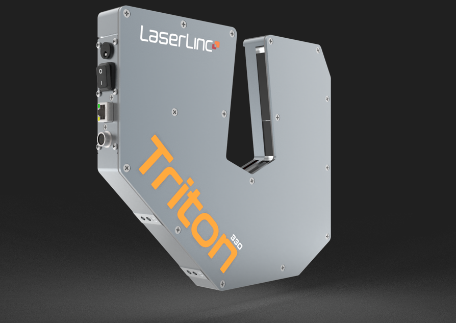
| Average OD | Average of specified simultaneous outside-diameter axes at a defined axial location, product temperature, and acquisition setting | One-axis reading, changing orientation, different filters, hot versus conditioned product | Axion or Triton laser micrometer |
| Ovality | A documented calculation using specified maximum and minimum outside dimensions or a defined multi-axis estimate | Different equations, insufficient angular coverage, rotating oval product | Triple-axis Triton or application-specific full contour method |
| Minimum wall | Minimum reported wall among defined acoustic paths, section locations, or circumferential observations under a specified method | Average wall compared with minimum wall, different clock positions, sample deformation | UltraGauge, BenchLinc UT, or an approved offline method |
| Calculated ID | ID calculated from synchronized OD and wall information using an approved geometry model at the same physical product location | OD and wall data paired from different lengths, nonconcentric geometry, treating calculated ID as direct ID | Synchronized laser and ultrasonic measurement |
| Taper or profile | Diameter or contour as a function of axial position, including defined zones, transition criteria, length origin, and sampling interval | Different zero points, spot checks versus continuous scan, product tension or sag | Inline bump/taper workflow or Metron full-length scan |
| Surface defect | A defined 3D contour event or dimensional excursion exceeding approved length, depth, height, width, area, or classification rules | Visual cosmetic judgment versus geometric threshold, blind areas between diameter axes | FlawSense or another validated surface-inspection method |
Put the intended use in one sentence
A useful intended-use statement is specific enough that another engineer can tell what is included and what is not. For example:
“The system will measure and record the three-axis average OD and estimated ovality of dry, stabilized Pebax tubing downstream of the cooling tank, provide high and low alarms, store the approved recipe with the run record, and supply process-monitoring data. Finished-product release remains based on the approved offline method.”
That sentence immediately creates useful questions about gauge location, air wiping, product stabilization, axis count, recipe control, alarm challenges, data records, correlation, and whether the inline result is informational or used for disposition.
Inline, benchtop, and full-length medical tubing measurement require different validation plans
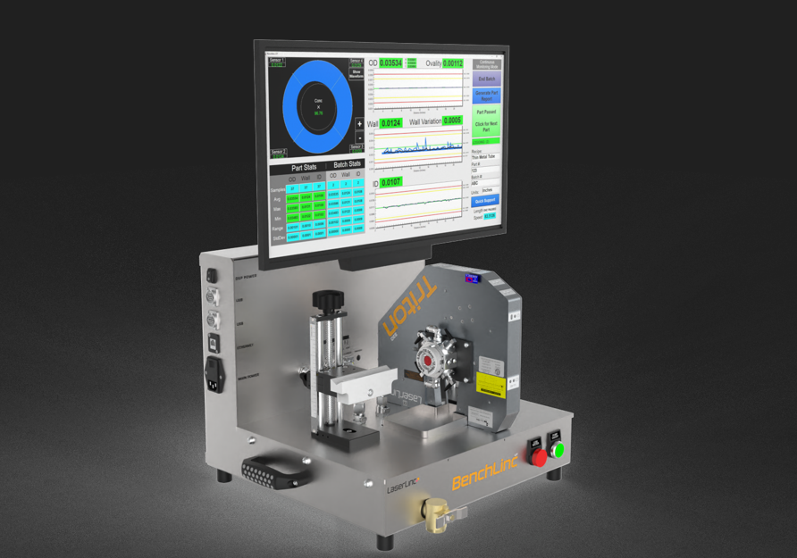
The measurement system and workflow changes the sources of variation. LaserLinc’s integrated approach spans inline laser and ultrasonic measurement, short-sample BenchLinc systems, full-length Metron scanning, surface inspection, and Total Vu visualization. The most useful architecture may combine more than one workflow rather than asking one station to answer every quality question.[14][15][17]
Challenge line speed, product wander, water removal, temperature, vibration, station delay, alarms, communications, control response, and the relationship between the measured hot or in-process dimension and the finished product.
Challenge sample preparation, conditioning, cut quality, mandrel selection, insertion depth, rotation, fixture force, cleanliness, operator loading, recipe selection, and repeated measurement of flexible or rigid parts.
Challenge part origin, straightness, tension, sag, supports, scan speed, axial position, zone definitions, transitions, feature detection, reporting, and the difference between product geometry and fixture-induced motion.

How to plan a useful medical tubing Gage R&R study
“Gage R&R” is the common manufacturing spelling, while “Gauge R&R” is also widely used. The important point is not the spelling. It is whether the experiment represents the actual measurement process. NIST’s guidance emphasizes deliberate selection of artifacts or parts, operators, gauges, configurations, and other measurement conditions rather than treating the instrument as the only source of variation.[5][6]
Represent the expected product range and include meaningful part-to-part variation. A study built only from nearly identical nominal parts can be hard to interpret.
Define whether the part remains in place or is completely removed, reloaded, realigned, and remeasured. Those are different repeatability questions.
Include the factors that realistically change: operators, fixtures, stations, gauges, shifts, days, recipes, setup personnel, or software configurations.
Prevent the measurement sequence and prior result from influencing how the next part is loaded, adjusted, or accepted.
Study performance across the validated size range rather than assuming the result at one nominal diameter applies to every product.
Compare results with suitable reference values and inspect whether the difference changes by size, geometry, material, or product condition.[7]
A short study may miss drift, maintenance effects, temperature changes, software changes, or differences between shifts and production days.
Interpret the result against the tolerance, guard band, product risk, and intended use. Do not let one generic percentage replace engineering judgment.
For an automated system, “operator” may not be the main reproducibility factor
A highly automated measurement station may show very little difference between people pressing the start button. That does not mean reproducibility is irrelevant. The meaningful factor may be who loaded the sample, which fixture was used, which recipe was selected, which gauge or station ran the part, whether the optics were cleaned, whether the system was restarted, or whether the study was repeated on another day.
A practical Gage R&R sequence
- Freeze the intended method. Approve the product condition, fixture, recipe, filters, calculations, cleaning, loading, and reporting instructions before the formal study.
- Select representative parts. Cover the intended range and known geometry risks. Preserve part identity without revealing prior results to the person measuring.
- Verify the equipment state. Confirm calibration status, routine verification, maintenance, environment, and approved software configuration.
- Randomize the sequence. Avoid measuring every part in the same order and avoid allowing the user to “measure toward” a known value.
- Include complete re-presentation where appropriate. Remove and reload the part if loading is part of the routine method.
- Analyze more than one output. Review repeatability, reproducibility, part interaction, bias, range effects, residual patterns, outliers, and practical tolerance impact.
- Investigate the mechanism. A failed result should lead to fixture, handling, product, software, environmental, or instrument diagnosis rather than an immediate attempt to average away the variation.
- Correct, document, and rerun. Treat the revised method as a controlled change and repeat the relevant study rather than combining incompatible datasets.
How to correlate inline and lab measurements on medical tubing
Inline-to-lab correlation is one of the most valuable and most misunderstood parts of medical tubing measurement validation. A strong correlation study does not ask only whether two columns of numbers move together. It asks whether the two methods observe the same product location, under sufficiently comparable conditions, with a difference that is understood and acceptable for the intended decision.
Inline tubing may be warm, moving, pressurized, or under tension. A cut lab sample may cool, shrink, ovalize, relax, or change after being removed from the process.
Compare measurements from the same axial region. Time-delay estimates are useful, but encoder or length-based tracking is stronger when speed changes or exact location matters.
A three-axis average OD, a single micrometer reading, a maximum contour diameter, and a rotated bench average may all be valid results without being the same feature being measured.
Do not compare thousands of inline readings across several feet of product with one selected bench reading and assume the averages represent the same thing.
Document averaging, smoothing, outlier handling, axis calculations, wall paths, zone definitions, and report rounding on both methods.
A familiar manual method is not automatically a gold standard. Resolution, fixture force, operator technique, sectioning, mandrel fit, and uncertainty may limit the comparison.
Why R² is not enough
Two methods can have a very high correlation coefficient and still differ by an amount that is unacceptable for the tolerance. They may also share a proportional bias that grows across the range. Difference-based analysis, including mean bias, the pattern of differences over the measurement range, and limits of agreement, provides information that a correlation coefficient alone does not. NIST’s Bland-Altman guidance specifically uses the mean difference to show bias and the agreement limits to assess whether method differences are practically significant.[10]
| Correlation step | What to control | What to analyze | Typical failure |
|---|---|---|---|
| 1. Pair the samples | Mark or length-track the same physical product region | Completeness of pairing and timing or position error | Comparing adjacent but different pieces of tubing |
| 2. Standardize product condition | Temperature, conditioning time, tension, internal pressure, and sample handling | Hot-to-cold shift, relaxation, shrinkage, and deformation | Calling a real physical change “gauge bias” |
| 3. Match definitions | Axes, wall path, zone, statistic, averaging, and rounding | Whether both methods report the same quantity | Average OD compared with one-axis OD or minimum wall |
| 4. Cover the range | Products and conditions across the intended operating envelope | Constant bias, proportional bias, nonlinear effects, and material interactions | Nominal-only study that misses size-dependent disagreement |
| 5. Review paired differences | Approved statistical plan and acceptance limits | Bias, spread, limits of agreement, residuals, and outliers | Declaring success from R² alone |
| 6. Define use | Which method controls setup, monitoring, release, or investigation | Decision risk and whether a correction or separate acceptance rule is justified | Forcing two different methods to be numerically interchangeable |
Calibration and verification for medical tubing measurement equipment
Calibration is foundational, but it should be designed around the actual measurement range and intended use. NIST defines metrological traceability through a documented, unbroken chain of calibrations in which each link contributes to measurement uncertainty. NIST also makes an important distinction: traceability is a property of a measurement result, not simply a label attached to an instrument.[9]
Use suitable reference values near the relevant low, middle, and high portions of the approved range. One convenient nominal pin may not reveal range-dependent bias or linearity.
A round pin is useful for a laser micrometer, but it does not represent every flexible, oval, rectangular, tapered, braided, or multi-lumen product presentation.
Clean the optics and standards, stabilize the environment where required, document the setup, and avoid touching or fixturing the standard in a way that changes the result.
When practical, record the condition before adjustment as well as the final condition. An as-found failure may require product-impact assessment rather than only a calibration correction.
Use an approved check at startup, changeover, scheduled intervals, or after maintenance when the risk justifies it. Define the reaction when the check is outside limits.
A reference pin can confirm optical dimensional performance, but it does not challenge sample loading, mandrel fit, wall-path alignment, software zones, or full-length part handling.
The standard, calibration process, environment, resolution, repeatability, geometry, and corrections all contribute to the confidence of the reported result.
Moving the gauge, replacing electronics, changing firmware, modifying a fixture, or altering calculations may require more than the routine calibration check.
Laser and ultrasonic systems do not use identical calibration logic
In a laser micrometer validation, a dimensional reference check is important but only one part of the evidence. A laser micrometer measures the outside silhouette and can be checked with suitable dimensional references. An ultrasonic wall system depends on acoustic transit time, interface detection, material behavior, transducer selection, positioning, and the approved calculation model. Representative product testing and material- or application-specific setup may therefore be important even when the electronics are within calibration.[14]
For a quick planning tool, use the Gauge Advisor Calibration Pin Calculator. The actual reference set, interval, acceptance limits, and reaction plan should still be approved through the manufacturer’s calibration and validation procedures.
What belongs in IQ, OQ, and PQ for a medical tubing measurement system?
The exact documents and names vary by company, but the underlying logic is consistent. IQ establishes the approved installation. OQ challenges the operating envelope and control functions. PQ demonstrates consistent performance in the routine production workflow. Medical-device process-validation guidance defines these phases in essentially that sequence and expects approved protocols, objective evidence, acceptance criteria, deviations, and final conclusions.[1]
Before IQ: user requirements, risk, and protocol prerequisites
IQ should not be the first time the intended use is written down. Before installation, define the product range, measurements, tolerances, workflow, environment, users, records, interfaces, controls, and acceptance decisions the system must support.
Define
- Product families, materials, constructions, and ranges
- features being measured, calculations, units, resolution, and report rounding
- Inline, benchtop, full-length, or combined workflow
- Informational, process-control, release, or investigation use
- Required recipes, reports, retention, communications, and user roles
- Applicable internal procedures, standards, and risk controls
Confirm
- Representative sample feasibility
- Gauge range, axes, transducers, fixtures, and sample handling
- Factory acceptance scope and deliverables
- Calibration and reference-standard strategy
- Protocol ownership and approval responsibilities
- Training, installation, startup, and validation schedule
Installation Qualification: prove the approved system is installed correctly
IQ should create a controlled record of what was installed, where it was installed, and whether it matches the approved design and supplier requirements. The GHTF guidance describes IQ as objective evidence that the installation adheres to approved specifications and supplier recommendations.[1]
Hardware and environment
- Model, serial number, measurement range, and configuration
- Mounting, alignment, guarding, product path, and access
- Power, air, water, network, environmental, and utility requirements
- Gauge location, stabilization distance, air wipe, and product support
- Reference standards and current calibration status
- Preventive maintenance and spare-parts information
Software and documentation
- Computer, operating system, application, firmware, and version records
- Approved licenses, configuration files, recipes, and permissions
- Manuals, drawings, certificates, backups, and recovery instructions
- PLC, OPC-UA, discrete I/O, encoder, printer, and network connections
- Safety checks, interlocks, and emergency recovery
- Training prerequisites and controlled procedures
Operational Qualification: challenge the measurement and software operating envelope
OQ should demonstrate that the system functions through its approved operating range and that limits, alarms, calculations, records, and interfaces behave as intended. GHTF guidance connects OQ with establishing control limits and action levels that result in product meeting predetermined requirements, including anticipated or boundary conditions.[1]
Measurement challenges
- Low, nominal, and high portions of the approved range
- Relevant product materials, geometries, surfaces, and wall ranges
- Repeatability after complete removal and re-presentation
- Bias or comparison to suitable references across the range
- Product wander, rotation, vibration, water, temperature, and line-speed effects
- Fixture, mandrel, support, tension, and alignment boundaries
Functional challenges
- High and low alarms, warning limits, rejects, and reaction logic
- Recipe selection, range enforcement, calculations, filters, and rounding
- Report content, export, record identity, and data transfer
- Encoder, PLC, OPC-UA, discrete I/O, and communication failure
- Power loss, restart, backup, restore, user access, and recovery
- Closed-loop limits, manual/automatic states, delay, and safe fallback
Performance Qualification: demonstrate the routine process with actual users and products
PQ moves from controlled challenges to the normal production environment. The GHTF guidance describes PQ as objective evidence that the process, under anticipated conditions, consistently produces product meeting predetermined requirements.[1]
Use routine conditions
- Approved production materials, products, recipes, and ranges
- Trained production and quality personnel
- Normal startup, changeover, cleaning, loading, and shutdown procedures
- Relevant shifts, days, lots, fixtures, stations, or product families
- Actual reports, records, alarms, review, and disposition workflow
- Approved calibration and verification state
Demonstrate consistency
- Repeatable measurement performance in routine use
- Agreement with the approved reference or release method where required
- Acceptable deviations, investigations, and corrective actions
- Operator understanding of reaction plans
- Stable process and measurement trends
- Documented conclusion for the intended use and validated range
Final report, deviations, and maintaining the qualified state
The final report should connect the approved protocol, executed evidence, deviations, investigation results, statistical analysis, limitations, and conclusion. It should state what product range, configuration, software version, fixtures, methods, and uses are covered rather than simply saying “the gauge passed.”
- Resolve deviations before final approval or document an approved rationale and impact assessment.
- Identify open items, limitations, excluded products, and conditions requiring separate review.
- Define routine verification, calibration, preventive maintenance, training, and record review.
- Define which hardware, software, recipe, fixture, material, range, location, or procedural changes trigger assessment or revalidation.
- Preserve the raw data, calculations, executed records, approvals, and final report according to the quality system.
Validate measurement software, recipes, reports, and automated control
Modern medical tubing gauges do more than display a dimension. They calculate ovality or ID, apply filters, associate measurements with recipes and zones, generate reports, communicate with other systems, and may control the process. FDA’s software-validation guidance applies general validation principles to software used to manufacture medical devices, while FDA’s February 2026 Computer Software Assurance guidance recommends a risk-based approach for production and quality-management-system software.[11][12]

Define calculations, units, ranges, screens, recipes, reports, alarms, interfaces, user roles, retention, control functions, and acceptance decisions.
Document application and firmware versions, recipe values, filters, zone maps, tolerances, calculations, permissions, report templates, and communication settings.
Challenge high-risk functions directly, especially calculations, disposition, alarms, data identity, transfer, access, and closed-loop commands.
Confirm that stored and exported records contain the correct part, recipe, lot, units, timestamps, results, limits, and approval-relevant context.
Verify encoders, PLC tags, OPC-UA data, printers, databases, network interruptions, retries, bad quality flags, and what happens when communication is lost.
Test power loss, restart, backup, restore, corrupted or missing recipe conditions, time synchronization, and recovery without silent loss or misassociation of data.
Verify delay, limits, actuator direction, manual/automatic transitions, output clamps, permissives, alarms, and safe behavior if the measurement becomes invalid.
Review patches, operating-system changes, firmware, recipes, report edits, PLC changes, cybersecurity controls, and hardware replacements for validation impact.
Why medical tubing measurement validation studies fail
When a study fails, I would resist the urge to change averaging, remove points, or blame the instrument before understanding the mechanism. The pattern of the failure usually points toward the right correction.
| Failure pattern | Likely cause | What to check next | Do not do this |
|---|---|---|---|
| Good reference-pin results, poor product repeatability | Product presentation, flexibility, vibration, water, fixture, mandrel, alignment, or method variability | Observe and document complete loading and measurement of the actual product | Repeatedly recalibrating a gauge that is already measuring the standard correctly |
| One operator or setup is different | Loading force, insertion depth, orientation, cleaning, recipe selection, interpretation, or training | Compare the exact work sequence and fixture condition | Removing the operator from the dataset without investigating the method |
| Bias changes with diameter | Linearity, range, geometry, fixture, reference, software correction, or method difference | Review paired differences across the full range and confirm reference suitability | Applying one constant offset to every product without evidence |
| Inline and bench match at nominal but not at limits | Temperature, proportional bias, relaxation, axis definition, wall model, or range-dependent fixture effect | Repeat paired testing at low, middle, and high conditions | Calling the methods equivalent from nominal-only data |
| Very poor percent R&R with stable repeated values | The selected parts contain too little part-to-part variation for that reporting basis | Review study purpose, part selection, percent tolerance, absolute variation, and decision risk | Concluding the gauge is bad from one percentage without inspecting the components |
| Large spread only after reloading | Fixture, mandrel, support, loading, orientation, sag, or location repeatability | Separate instrument repeatability from complete-method repeatability | Keeping the part fixed during the study when routine use requires reloading |
| Different result after software or recipe change | Filter, averaging, calculation, zone, units, report, firmware, or configuration difference | Compare controlled configuration records and raw-versus-reported data | Combining pre-change and post-change data as one study |
| Correlation looks excellent, but differences exceed tolerance | High R² with unacceptable constant or proportional bias | Use paired-difference and agreement analysis against predefined acceptance limits | Using correlation coefficient as proof of interchangeability |
| Study varies by day or shift | Environment, warm-up, maintenance, cleanliness, material, setup, product conditioning, or different equipment state | Trend the suspected condition and include time as a study factor | Reporting only the best short-term session |
| PQ fails while OQ passed | Routine users, materials, shifts, procedures, process variation, reports, or production conditions were not represented in OQ | Determine whether the method, process, training, or approved range needs correction | Loosening acceptance criteria after seeing the PQ result |
| Supplier test passed, site study fails | Different environment, product handling, mounting, software configuration, utilities, operators, references, or intended use | Compare the factory and site conditions requirement by requirement | Treating the FAT as a substitute for site qualification |
| Process data are unstable during the study | Actual manufacturing variation is being mixed into a measurement-system experiment | Use stable retained parts for MSA or separate process and measurement objectives | Blaming the gauge for product that changed between measurements |
Maintain the validated state of the measurement system
Validation is not a one-time event stored in a binder. The approved system has to remain controlled as the product mix, personnel, software, fixtures, equipment, environment, and process change. GHTF guidance explicitly treats continued monitoring and revalidation as part of the lifecycle.[1]
- Routine verificationDefine startup, changeover, periodic, and post-maintenance checks with documented acceptance and reaction limits.
- Calibration controlMaintain reference traceability, intervals, as-found review, uncertainty information, and product-impact procedures.
- Preventive maintenanceControl optical cleaning, alignment, transducers, fixtures, mandrels, product guides, moving stages, computers, and communications.
- Trend measurement healthReview verification results, bias, repeatability, alarms, rejects, drift, failed reports, communication errors, and service events.
- Training and proceduresKeep loading, cleaning, recipe, response, backup, recovery, and investigation instructions current and usable.
- Configuration controlProtect software, firmware, tolerances, filters, calculations, zones, reports, permissions, PLC logic, and network settings.
- Change assessmentEvaluate new products, range extensions, materials, fixtures, gauge relocation, repairs, replacements, updates, and process changes.
- Risk-based revalidationRepeat the affected IQ, OQ, PQ, MSA, correlation, or software evidence rather than automatically rerunning everything or nothing.
Medical tubing measurement validation project checklist
This is the information I would want before reviewing a new system, a failed study, or an inline-to-lab correlation problem. You do not need every item to start, but the drawing, measurement definition, current method, and actual problem are especially useful.
- Product drawing and controlled characteristicsNominals, tolerances, zones, transitions, surface requirements, and the dimensions that govern acceptance.
- Material and constructionPolymer, durometer, layers, lumens, braid, coil, filler, metallic reinforcement, color, surface, and flexibility.
- Complete dimensional rangeMinimum, nominal, maximum, startup excursions, product families, and future range extensions.
- Intended use of the resultSetup, process monitoring, alarm, closed-loop control, finished-part verification, release, or investigation.
- Current measurement methodInstrument, fixture, sample preparation, locations, calculations, frequency, resolution, and known limitations.
- Proposed measurement system and workflowInline laser, ultrasonic, surface inspection, BenchLinc, Metron, or a combined inline/offline workflow.
- Process and line conditionsLine speed, gauge location, water, product temperature, internal pressure, tension, vibration, motion, and available space.
- Fixtures and sample handlingMandrels, supports, loading force, rotation, alignment, straightening, tension, cut method, and conditioning.
- Reference standards and comparison methodTraceability, uncertainty, range, calibration status, fixture, and whether the method measures the same quantity.
- Existing study dataRaw Gage R&R, correlation, bias, capability, failed protocol, deviations, screenshots, trends, and not only the summary percentage.
- Software and data requirementsRecipes, filters, calculations, reports, users, records, export, SPC, OPC-UA, PLC, encoder, and control functions.
- Validation phase and timelineURS, feasibility, FAT, IQ, OQ, PQ, transfer, launch, remediation, change control, and required completion date.
- Representative samplesGood, bad, low, nominal, high, difficult, and known-defect samples where feasible.
- Customer quality-system expectationsProtocol format, approvals, statistical requirements, record retention, cybersecurity, access, audit trail, and training needs.
Related medical tubing measurement tools and guides
This validation guide is intentionally system-level. Use these Gauge Advisor resources to go deeper into the measurement system and workflow, sensor selection, calibration planning, process capability, troubleshooting, and finished-part workflow.
Medical tubing measurement validation FAQ
What is medical tubing measurement system validation?
It is documented evidence that the complete measurement system is fit for its intended use. The system includes the sensor, electronics, software, fixtures, standards, product condition, operators, procedures, calculations, records, and decision rules, not only the gauge head.
Is calibration enough to validate a laser micrometer or ultrasonic gauge?
No. Calibration establishes an important relationship to suitable references under defined conditions. Validation also addresses the actual product, range, presentation, fixture, software, method variation, bias, records, users, operating limits, and intended decision.
Is it spelled Gage R&R or Gauge R&R?
Both spellings are used. “Gage R&R” is common in manufacturing quality systems, while “Gauge R&R” is standard English spelling. They generally refer to the same repeatability-and-reproducibility study concept.
How many parts, operators, and repeats are required for a medical tubing Gage R&R?
There is no universal count that fits every automated, inline, benchtop, destructive, or full-length method. The protocol should justify enough parts and repeated conditions to represent the intended range and estimate the variation relevant to the decision. For automated systems, fixtures, setups, days, gauges, recipes, or stations may be more meaningful reproducibility factors than the person pressing Start.
Does Gage R&R replace IQ, OQ, or PQ?
No. Gage R&R characterizes selected components of measurement variation. IQ documents installation, OQ challenges approved operating conditions and functions, and PQ demonstrates routine performance with actual products, users, procedures, and production conditions. One study can support another, but they answer different questions.
Can supplier FAT, IQ, or OQ documents be used?
Supplier documents and factory testing can provide valuable evidence, configuration records, and protocol content. The medical-device manufacturer still has to determine whether the installation, intended use, products, environment, software configuration, procedures, and acceptance criteria are suitable at its site.
Should inline and bench measurements match exactly?
Not automatically. Inline and bench methods may observe different temperatures, tension, support, relaxation, angular coverage, axial locations, sampling density, and calculations. The goal is an understood and acceptable relationship for the intended use, not a forced expectation that physically different methods always produce identical values.
Does a high R² prove that two measurement methods agree?
No. A high correlation coefficient can coexist with a large constant or proportional difference. Review paired differences, bias, range effects, residuals, and limits of agreement against predefined practical acceptance criteria.
Can a laser micrometer measure medical tubing wall thickness or ID?
A laser micrometer directly measures the outside silhouette. It does not directly measure wall thickness or ID. ID can be calculated when valid wall measurements are synchronized with OD at the same physical tube location and the approved geometry model is appropriate.
What should be challenged during Operational Qualification?
Challenge the approved measurement range, relevant product and geometry conditions, fixtures, loading, line speed, temperature, water, vibration, repeatability, bias, recipes, calculations, filters, alarms, reports, communications, access, backup and recovery, and any automated control or disposition functions according to risk.
When should a medical tubing measurement system be revalidated?
Perform a documented impact assessment when hardware, location, fixtures, standards, product range, material, method, software, firmware, recipes, calculations, reports, interfaces, procedures, or intended use changes. Repeat the affected evidence based on risk rather than assuming every change requires either a full revalidation or no testing.
Is a LaserLinc measurement system FDA compliant?
No piece of measurement equipment is “FDA compliant” in isolation. LaserLinc hardware and software can support measurement, records, verification, and process-control workflows, but the medical-device manufacturer is responsible for its quality system, intended use, validation, procedures, training, records, acceptance decisions, and ongoing control.
What should I send for a medical measurement validation review?
Send the product drawing, material and construction, dimensional range and tolerances, intended use, current and proposed methods, line or fixture conditions, existing raw study data, software and reporting needs, validation phase, timeline, and representative samples when available.
References and source notes
The sources are collapsible to keep the main guide readable and open automatically when printing.
Open technical and regulatory references17 sources
Gauge Advisor is the authorized LaserLinc sales and applications support partner. LaserLinc sources document current product and software architecture. FDA, IMDRF/GHTF, ISO, and NIST sources provide independent regulatory, validation, metrology, and statistical context. This article is practical applications guidance and is not legal, regulatory, or quality-system advice.
- Global Harmonization Task Force Study Group 3, “Quality Management Systems: Process Validation Guidance,” Edition 2, January 2004. Medical-device guidance covering validation planning, protocols, statistical methods, IQ, OQ, PQ, continued monitoring, change control, and revalidation.
- U.S. Food and Drug Administration, “Quality Management System Regulation (QMSR).” FDA overview of the QMSR that became effective February 2, 2026 and incorporates ISO 13485:2016 by reference.
- Electronic Code of Federal Regulations, Title 21, Part 820, Quality Management System Regulation. Current federal regulatory text for medical-device quality systems.
- International Organization for Standardization, ISO 13485:2016, “Medical devices: Quality management systems: Requirements for regulatory purposes.”
- NIST/SEMATECH e-Handbook of Statistical Methods, “Gauge R & R Studies.” Overview of measurement-system repeatability, reproducibility, stability, bias, resolution, linearity, and related variability components.
- NIST/SEMATECH e-Handbook of Statistical Methods, “Gauge R & R Design Considerations.” Guidance on selecting artifacts, operators, gauges, configurations, and the structure of the experiment.
- NIST/SEMATECH e-Handbook of Statistical Methods, “Analysis of Bias.” Statistical context for assessing differences between measurement results and reference values.
- NIST/SEMATECH e-Handbook of Statistical Methods, “Quantifying Uncertainties from a Gauge Study.” Context for combining gauge-study variability with additional uncertainty components.
- National Institute of Standards and Technology, “Metrological Traceability: Frequently Asked Questions and NIST Policy.” Definitions and practical limits of traceability, calibration chains, and measurement uncertainty.
- NIST Dataplot, “Bland-Altman Plot.” Difference-based method-comparison guidance covering bias, trends across the range, and limits of agreement.
- U.S. Food and Drug Administration, “General Principles of Software Validation.” General validation principles for medical-device software and software used to design, develop, or manufacture medical devices.
- U.S. Food and Drug Administration, “Computer Software Assurance for Production and Quality Management System Software,” Final Guidance, February 2026. Risk-based recommendations for establishing confidence in production and QMS software.
- LaserLinc, “Triton: Three-Axis Laser Micrometers.” Official product information for three-axis measurement of round and elliptical products, average diameter, and estimated ovality.
- LaserLinc, “Ultrasonic Wall Thickness Measurement.” Official UltraGauge and AutoPilot information for wall thickness, concentricity, and combined tube-profile workflows.
- LaserLinc, “Sample Inspection.” Official BenchLinc and Metron information for short-sample and automated full-length inspection.
- LaserLinc, “Process Visualization.” Official Total Vu information for visualization, integrated measurement technologies, reporting, analysis, communications, and control.
- LaserLinc, “Are Your Measurement Systems Working Together?” Official overview of integrated inline measurement, finished-product verification, full-length inspection, reporting, and process control.
Need help planning the measurement and validation workflow?
Gauge Advisor is the authorized LaserLinc sales and applications support partner. I help medical tubing manufacturers review the measurement requirement, select and quote the appropriate LaserLinc architecture, coordinate sample testing and factory applications support, and organize the equipment information needed for implementation and validation planning.
The customer’s quality organization remains responsible for the protocol, statistical plan, acceptance criteria, approvals, regulatory interpretation, and final validated use. Gauge Advisor supports LaserLinc equipment selection and application planning; the manufacturer’s quality team owns the validation protocol and regulatory decisions.
- Drawing, feature being measured, tolerance, and workflow review
- Inline, benchtop, and full-length measurement system and workflow
- Laser, ultrasonic, surface, profile, and data requirements
- Representative sample testing and feasibility coordination
- Gage R&R and correlation problem framing
- IQ/OQ/PQ equipment and configuration inputs
- Quotations and LaserLinc factory coordination
- Ongoing local sales and applications support
Send the drawing, current method, study results, and the problem you are trying to solve. I will respond within one business day, often within a few hours.