Bump-and-taper tubing changes diameter along its length, so inspection must check each feature and transition. Compare a triple-axis micrometer for live outside-diameter (OD), ovality and feature tracking, Metron for a full-length scan of the cooled part, and FlawSense II for full-contour OD, true ovality and surface-shape inspection.
Gauge Advisor is an authorized LaserLinc sales and applications support representative. We help define the feature recipe, line architecture, equipment scope and manufacturer review.
Three valid starting paths
Choose by when the tubing is measured and which defects must be found.
Inspect the hot moving extrusion inline, scan the cooled finished length with Metron, or map complete outside-contour and surface geometry with FlawSense II.
Record dimensions and surface features along the tubing.
A single spot diameter cannot describe tubing that intentionally changes size. Choose live production feedback, full-length inspection after cooling or full-contour surface data according to the checks your process requires.
01
Slow startup approval
Operators wait for cut samples, ring gauges, microscopes or lab review before they know whether each bump, taper and plateau is acceptable.
02
Transition-length uncertainty
Small and large diameters may pass, yet a ramp begins late, ends early or contains overshoot that an isolated spot check misses.
03
Mixed good and bad parts
The line detects a problem but cannot reliably associate that event with the correct downstream cut part or sorter position.
04
Process drift after setup
A process that met specification at startup can drift during a long run. Alarms, reports or a properly configured control response help the team respond before more scrap is produced.
Strong project fit: the drawing contains more than one OD or transition zone, the finished length needs a repeatable scan, or the acceptance risk includes outside-contour or surface-relief events. If the product has one constant OD with no changing profile, start with a conventional laser micrometer application instead.
Inline triple-axis path
A virtual ring gauge turns a moving diameter trace into feature boundaries.
Think of the virtual ring gauge as a programmed software diameter—not a physical ring. As the tubing moves through the triple-axis micrometer, Total Vu uses live OD/ovality data, the cutter cycle and any required position reference to identify where the measured profile enters or leaves each recipe zone.
The drawing becomes a sequence of named zones with nominal dimensions, tolerances and length rules.
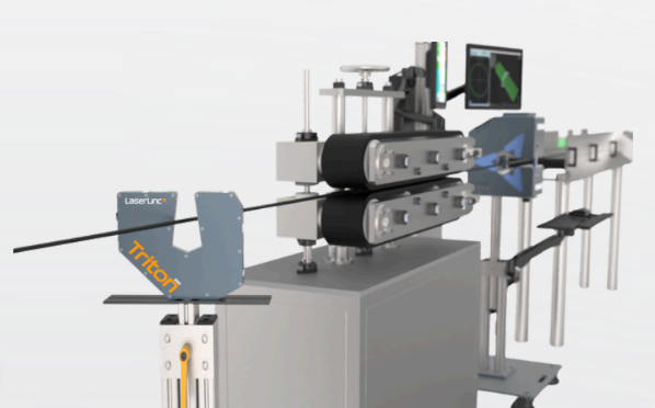
The inline triple-axis micrometer measures the outside profile without contacting the hot or moving tubing.
The cutter signal identifies the part boundary; encoder or speed data can locate readings within that part.
The software evaluates transitions and feature lengths, then records pass/fail and the required downstream action.
Measurement boundary: these bump-and-taper paths address the outside profile or outside surface. ID, wall thickness and concentricity are separate measurement projects, not additional bump-and-taper system choices.
Interactive profile anatomy
Example: small OD → transition → large OD → transition → small OD
Small-OD zone
Ramp up
Large-OD plateau
Ramp down
Small-OD zone
The recipe must define the diameter and length acceptance rule for every zone. Transition start, end, slope treatment, averaging and exclusions are not universal.
Why the length reference matters: the same OD value can belong to a valid plateau, a transition or the wrong feature. Product position gives that number context.
Inline extrusion architecture
Connect the triple-axis gauge to the part cycle—not only to line speed.
The cutter trigger establishes the part boundary. LaserLinc can read a cut or cycle signal from Conair, RDN, or another compatible puller/cutter control, then use encoder or speed data when more position detail is required within the part.
Representative inline architecture. The reviewed Conair, RDN or compatible cutter-cycle signal tells Total Vu where one part ends and the next begins. Gauge-to-cutter distance, signal type, timing, I/O and any additional encoder or speed reference remain line-specific.
1. Process recipe
Part zones, timing or length rules, product IDs and the production sequence that creates each feature.
2. Triple-axis gauge
Three simultaneous views measure the moving outside profile, OD and estimated ovality.
3. Cutter + position
Read the Conair, RDN or compatible cut-cycle signal; add encoder or speed feedback when needed.
4. Total Vu + I/O
Associate each reading with the correct part and zone, then manage recipes, records and handshakes.
5. Required action
Operator guidance, accept/reject, downstream disposition or a separately engineered control response.
Total Vu is the feature engine
Start with visibility, then add the amount of automation the process can safely support.
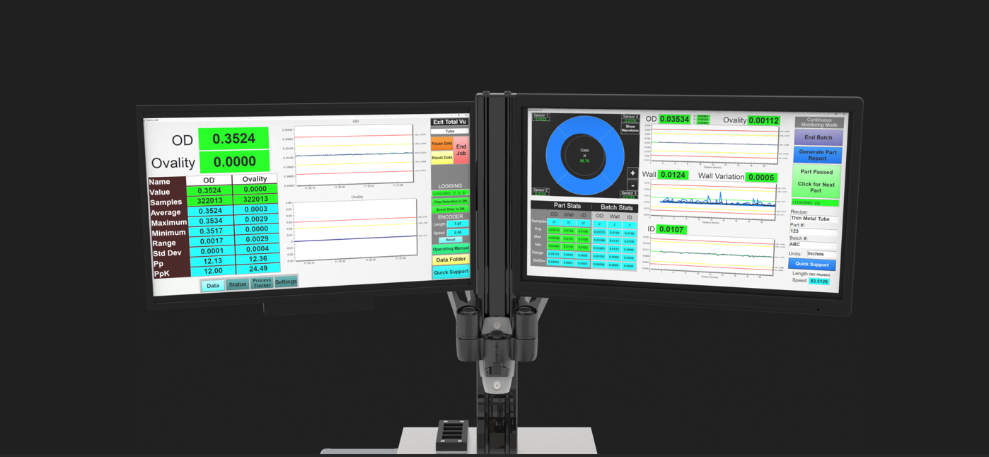
Total Vu brings measurements, feature recipes, part tracking and results into one customizable workflow. Choose the reporting, data sharing, sorting and optional closed-loop control functions that fit your line.
For cut-part tracking, Total Vu reads the cut or cycle signal available from a compatible Conair, RDN or other puller/cutter control. That input establishes which measured zones belong to which physical part; encoder or speed data may provide additional position between cut events.
Level 1Measure and guide setup
Live profile, zone results, alarms and operator adjustment during startup.
Level 2Track each cut part
Cutter-cycle synchronization, correct-part assignment, accept/reject records and downstream disposition.
Level 3Optional closed-loop control
Engineered adjustment after startup with defined authority, limits and fallback.
Integration boundary: confirm the available dry contact, pulse, PLC tag or network signal; trigger edge; gauge-to-cutter distance; cycle timing; parts in flight; signal-loss response and reject timing. Reading the cutter signal is separate from commanding puller speed, internal air or another optional process-control variable.
Compare measurement during extrusion and after cooling.
Live production feedback, cooled full-length dimensional inspection and full-contour surface inspection are different jobs. These three LaserLinc paths keep that choice understandable without turning every sensor family into a bump-and-taper recommendation.
Inline extrusion
Triple-axis bump-and-taper measurement
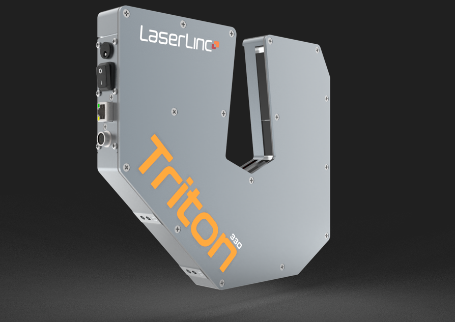
Three simultaneous diameter views track OD, ovality, transition position and feature length while the tubing is being produced. Total Vu combines those readings with the cutter or line-position signal so each recipe zone and cut part can be identified. The final Triton or triple-axis Axion model follows the OD range, tolerance, speed and installation.
Metron moves a cut, conditioned catheter, guidewire or tube through the selected measurement head and compares the complete length-positioned profile with its recipe. Use it for cooled-part verification, reports and release correlation—not real-time extrusion control.
FlawSense uses laser-line triangulation when a local bump, pit, scratch, raised feature or contour change may not be represented well by three diameter axes. Representative samples still determine whether the visible surface and required event size are suitable.
Use each inspection method for the checks it can perform.
Start with the decision the data must support. A triple-axis micrometer sees the hot moving extrusion, Metron scans the cooled part over its full length, and FlawSense II maps outside contour and localized surface relief. These systems perform different inspection tasks and can be used together when the application requires it.
1. Inline triple-axis
Use for live OD, estimated ovality, transition timing, feature length, cut-part tracking and an optional reviewed control response.
2. Metron full-length
Use for a controlled scan of the cooled cut part, length-positioned dimensions, reports and release-method correlation.
3. FlawSense full-contour
Use when complete outside contour, true ovality or localized raised and recessed surface events drive acceptance.
Do not force one method to answer every question: cooling, relaxation, tension, cut position, handling and visible surface behavior can change what each system sees. Correlate combined methods by product recipe and assign the release decision explicitly.
Start with when and what must be inspected: live inline OD and ovality points to triple-axis micrometry; a cooled full-length profile points to Metron; and complete outside contour or surface relief points to FlawSense II. ID, wall thickness and concentricity are separate measurement projects.
Selector boundary: use the result to organize the broader medical measurement need. Final triple-axis micrometer, Metron or FlawSense configuration—and all cutter signals, software, handling, sorting and validation details—require LaserLinc application review.
Send the profile and line sequence before choosing the gauge.
A complete specification is not required to start. The details below help identify suitable equipment and prepare an accurate quotation.
01
Part drawing and zone table
Small and large OD, ovality, feature lengths, transitions, exclusions, tolerances and product variants.
02
How the feature is produced
Extruder, die, line speed, puller, air/vacuum and the variable that creates each feature. Include the cutter manufacturer, model and available part-cycle signal.
03
Line speed and cycle
Normal and maximum speed, part pitch, continuous or intermittent sequence, acceleration and changeover behavior.
04
Product state and presentation
Inline space, cooling state and passline; Metron cut-part handling; or the way representative parts and surface events can be presented to FlawSense.
05
Cutter and position signals
Conair, RDN or other cutter model; dry contact, pulse, PLC tag or network path; gauge-to-cutter distance; encoder, speed feedback and PLC ownership.
06
Pass/fail action
Alarm, operator response, cutter, sorter, reject location, parts in flight, correct cut-part assignment and required records.
07
Data and integration
Reports, logs, lot and recipe fields, OPC UA or plant interface, PLC/HMI, MES and data-retention needs.
08
References and samples
Metron or current QA reports, accepted correlation parts, FlawSense surface or contour samples, MSA expectations and the authority that releases product.
Fastest start: send one drawing, a short line video or layout, normal/max line speed, the current inspection method, and the production problem you want the system to solve.
Engineering and buying questions
Bump & taper tubing measurement FAQ
What does LaserLinc's virtual ring gauge do?
It is software logic that uses live diameter/ovality data and synchronized product length to identify feature transitions and feature lengths. It does not physically contact the tubing. The recipe and correlation method still need to match the drawing and accepted offline inspection.
Which bump-and-taper system fits the application?
Use a triple-axis micrometer for live inline OD, ovality and feature tracking; Metron for a controlled full-length scan of the cooled cut part; and FlawSense II when complete outside contour, true ovality or localized raised and recessed surface events drive acceptance. Some validation plans use more than one path.
Can these systems measure wall thickness or inside diameter?
Not as part of these three bump-and-taper paths. Triple-axis micrometry and Metron measure the outside profile, while FlawSense maps the qualified visible outside contour and surface relief. ID, wall thickness and concentricity require a separate measurement project and should not be assumed from outside dimensions alone.
How does the inline system know where each cut part begins and ends?
Total Vu can read a reviewed cut or cycle signal from a compatible Conair, RDN or other puller/cutter control. The project must confirm the signal type, trigger edge, cycle timing, gauge-to-cutter distance, parts in flight, any encoder or speed reference and the failure response.
Can the inline system reject bad parts automatically?
It can support in-process accept/reject decisions and automated sorting when the cutter signal, sorter, part tracking, I/O, distances, delays and failure behavior are included in the engineered scope. A measurement alarm by itself does not guarantee the correct physical part is rejected.
Can it automatically control the extrusion process?
LaserLinc offers optional closed-loop control, but the useful manipulated variable is application-specific. The project must confirm the actuator, authority, limits, process delay, startup and recipe logic, manual mode, signal-loss response and safety responsibilities.
Does inline measurement replace Metron or FlawSense?
No. Inline triple-axis measurement provides production-state feedback. Metron automates the cooled finished-part dimensional profile. FlawSense addresses full-contour and localized outside-surface events. A validated workflow can combine them with documented correlation and clearly assigned release criteria.
What data can Total Vu retain or share?
Total Vu can save measurement logs and part results, create customizable reports, and share selected data with your plant systems. We'll confirm the measurements, report format, connection and retention requirements your team needs, along with any software or communications options.
Send the drawing, feature sequence, line speed, current inspection method and desired line action. Gauge Advisor will organize the application for LaserLinc review, equipment selection and quotation.
Equipment guidance is part of the represented-equipment sales process. Final capability, integration, validation and performance terms require manufacturer application review and written scope.
Interactive medical selector
Build your preliminary profile
Answer five guided questions to narrow the inline or offline measurement paths worth reviewing.
We use essential cookies for site operation and optional analytics cookies to understand how visitors use our pages and tools. Choose Accept All, Reject, or Preferences.
Cookie Preferences
Choose whether to allow optional analytics cookies. Essential cookies are always active.
Essential cookies enable basic functions and are necessary for the proper function of the website.
Name
Description
Duration
Cookie Preferences
This cookie is used to store the user's cookie consent preferences.
180 days
Statistics cookies collect information anonymously. This information helps us understand how visitors use our website.
Measures website traffic and interactions to help Gauge Advisor understand which pages and tools are useful.