
Anode & cathode coating · Calendering
Battery Electrode Measurement for Coating & Calendering
See coating variation while the web is running. Scantech systems bring coat weight, dry thickness and calculated density into the decisions you make on anode and cathode lines.
Start with the result you need: coating loading, lane uniformity, final thickness or compaction. Then choose the sensors and measurement positions that support it.
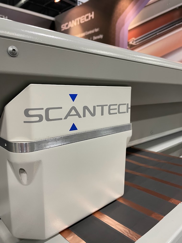
Define the result
Coat weight, thickness and density answer different questions.
A useful measurement starts with a clear definition of the material being evaluated: the foil, one coating face, both faces or the complete electrode.
| What you need | Measurement approach | What it helps you evaluate |
|---|---|---|
| Coating basis weight | X-ray transmission, calibrated for the material. Net coat weight also needs a suitable foil baseline. | Mass per unit area, loading consistency and variation across coating lanes. |
| Physical dry thickness | Optical or confocal measurement, with the foil contribution handled when net coating thickness is required. | Dry coating build, final electrode thickness and the effect of calendering. |
| Apparent coating density | A calculation using matching net coating mass and net coating thickness. | Compaction and recipe consistency for the defined dry coating layer. |
Swipe to see all columns.
Build the measurement around your process. Single-sided, tandem and simultaneous two-sided coating can need different sensor combinations and station layouts.
From foil to finished coating
Put the measurement where it can guide the next decision.
Inline profiles complement laboratory checks by showing changes between samples. Wet, dry and finished-electrode results each describe a different point in the process.
Incoming foil
Establish the substrate contribution before coating. Foil variation matters when the goal is net coating loading.
Wet coating
See changes in applied slurry earlier in the process. Wet coat weight includes liquid and is not automatically dry solids loading.
After drying
Evaluate the dried coating and lane profile. Choose basis weight, physical thickness or both to suit the acceptance criteria.
At the calender
Review thickness before or after compaction, with matching mass measurements when calculated density is needed.

Net coat weight needs a corresponding foil measurement.
Same Spot coordinates the scan paths of substrate and coated-web stations so the calculation compares corresponding material positions. Line travel, speed changes and web alignment all matter when setting up that relationship.
For two-sided coating, decide whether you need combined loading or separate results for each face. The coating sequence and measurement locations determine what can be separated.
Calendering & compaction
Follow the change in thickness—and the density behind it.
Calendering changes electrode thickness and compaction. Scantech configurations can evaluate thickness after the calender, compare before and after, or combine thickness with basis weight for calculated density.
For coating density, the mass and thickness values must describe the same dry coating layer. The foil contribution and one-sided or two-sided definition need to be handled consistently.
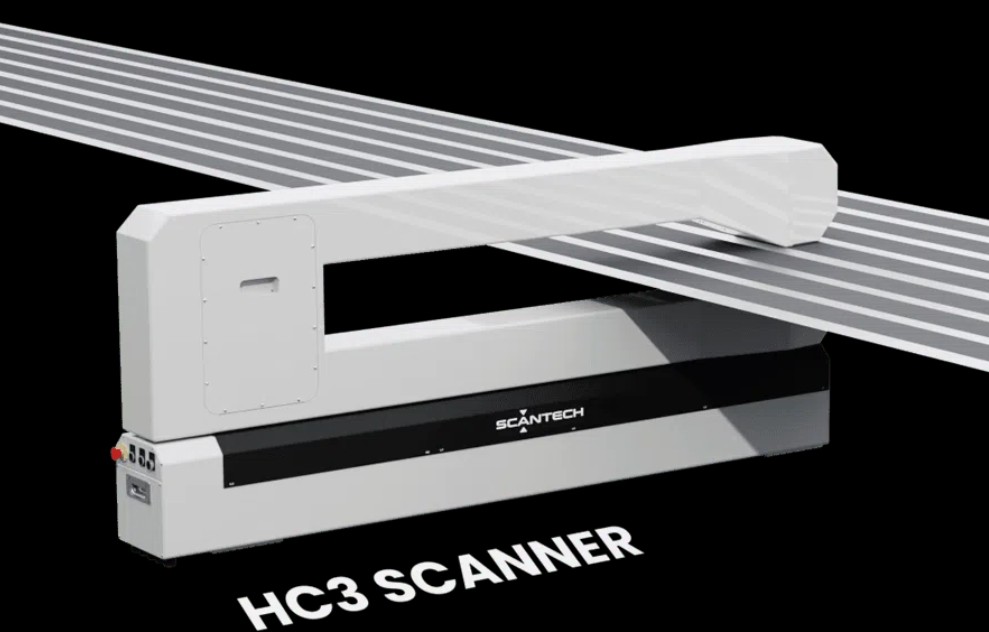
FLEXSCAN operator software
Make lane variation easier to see and act on.
View cross-web profiles and trends in the context of the product you are running. Set up lane definitions, targets, recipes and alarms around the measurements your system provides.
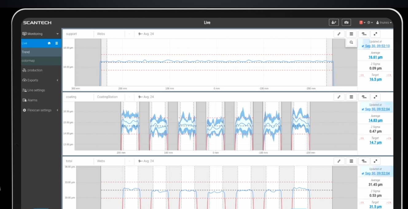
Compare coating lanes
Keep lane results and substrate or total-web views distinct, so the operator can see where a change is happening.
Connect production data
Define the required PLC or plant-data connection, including OPC UA where specified, and the identifiers needed to relate results to production.
Keep useful records
Specify operational roll views and reporting. TREX adds deeper report retrieval and organization when included in the software package.
Need to see coating defects too? Web visual inspection can complement dimensional and mass measurements. Review the target defects and imaging requirements alongside the coating measurement.
Complete system selection
Choose the architecture around the electrode line.
Sensor selection, scanner access, station timing and the operator interface work together. A compact C-frame may suit one location; an O-frame or a coordinated set of scanners may fit another.
I help define the line requirements and coordinate evaluation with Scantech, including representative foil and coated samples, chemistry, required ranges and the agreed laboratory reference.
Explore complete web gauging systems →Plan the response as well as the reading.
Decide whether the measurement should inform an operator, feed a quality system or support automatic process correction. Closed-loop control needs compatible actuators, machine interfaces and a commissioned control strategy.
Start with X-ray transmission web gauging for the mass-measurement approach, or compare the wider coating measurement and tension-control workflow.
Watch the overview
Scantech lithium-ion battery measurement overview
See Scantech’s approach to electrode and separator-film measurement in this manufacturer overview.

Plan the project
Useful next steps for electrode lines.
Explore how material usage and production assumptions affect potential savings.
Compare units and relationships using the appropriate material assumptions.
Evaluate visually detectable defects separately from coating loading and thickness.
Review measurement, line integration and web-handling considerations together.
Replacing a beta or gamma gauge?
Review X-ray suitability for your electrode materials alongside scanner fit, software and existing machine interfaces.
Manufacturer resources: single-sided coating · calendering · battery measurement overview (electrodes and separator film).
Common questions
Battery electrode measurement FAQ.
Does an X-ray gauge measure coating thickness directly?
Transmission responds to the material in the beam and can provide a calibrated basis-weight result. Converting that result to thickness needs an appropriate density and material model. Optical or confocal measurement provides a separate physical-thickness measurement.
How is the coating weight separated from the foil?
Use a suitable foil baseline and a defined comparison with the coated web. Registered upstream and downstream measurements help account for substrate variation when net coating weight is the required output.
Can the two electrode faces be measured separately?
That depends on the coating sequence and measurement positions. A final total-web measurement alone does not establish how the coating is divided between the two faces.
Should measurement be wet, dry or after calendering?
Wet measurement supports earlier coating feedback. Dry measurement evaluates the dried material. Calender measurements address thickness and compaction. Choose the locations around the decisions and acceptance criteria for your line.
What is needed to calculate coating density?
Matching coating mass per area and coating thickness, with the foil contribution removed consistently. Both values must refer to the same layer, material condition and one-sided or two-sided definition.
Application review
Let’s review your electrode line.
Send the process layout and the result you need to improve. I’ll help turn that into a measurement scope for Scantech to evaluate.
Helpful details to send
- Anode or cathode chemistry, foil and coating construction
- Single-sided, tandem or simultaneous coating; lane and gap layout
- Wet, dry and calender measurement positions
- Web width, line speed, ranges and tolerances
- Reference samples, laboratory method, data and control requirements
A drawing, sample description or current gauge specification is a useful starting point.