Updated August 21, 2026
Medical tube extrusion measurement is not one gauge placed after the cooling tank. It is a coordinated measurement stack: outside diameter and shape, wall and lumen geometry, surface quality, finished-part verification, and the data layer that connects those results to the process.
The right architecture depends on what the drawing actually controls, where the product becomes stable, how the tube moves, which defects create risk, and whether the result is needed for immediate process feedback, release inspection, or both. LaserLinc organizes these needs across laser micrometers, UltraGauge ultrasonics, FlawSense surface inspection, BenchLinc and Metron sample systems, and Total Vu visualization and control.[1]
Connected process path: Connect inline OD, ultrasonic wall, surface-defect inspection, and finished-part QA so each stage measures the feature it can control or release.
Related next steps: medical-device measurement and inspection, medical-tubing measurement selector, medical-tubing wall-thickness measurement, medical-tubing surface-defect detection, and laser micrometers.
Five layers of medical tubing measurement
A useful system does not begin with a brand or sensor model. It begins with the dimensions, defects, workflow, and decisions that must be supported.
Outside diameter & shape
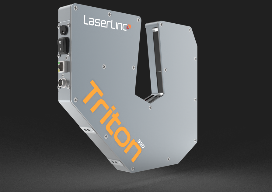
Laser micrometers monitor OD, width, height, and estimated ovality without touching the tube. Triple-axis Triton systems are a common starting point for critical round tubing; Axion systems cover one- and two-axis applications.
Choose the axis count →Wall & internal geometry
UltraGauge ultrasonics measures wall interfaces and concentricity in real time. When synchronized with laser OD, the system can calculate ID and present a more complete tube cross-section.
Select an ultrasonic path →Surface quality
FlawSense maps the full outside contour to find pits, scratches, cracks, blisters, wrinkles, and other surface events that ordinary OD trending may miss.
Review defect detection →Finished-part verification
BenchLinc and Metron turn the same measurement technologies into repeatable benchtop or automated scanning workflows for cut samples, rigid tubes, long catheters, guidewires, and profiles.
Compare QA workflows →Visualization & control
Total Vu brings dimensions, trends, SPC, reporting, recipes, communications, and optional feedback control into one operator and quality workflow.
Estimate the ROI →Where each measurement belongs on the line
Select a stage to see what can be learned there, what technology commonly fits, and what can make the data misleading.
Build a starting medical tubing measurement stack
Select the characteristics, workflow, product handling, and data objective. The result is a planning recommendation, not a final equipment quotation.
Match the requirement to the measurement workflow
Search by dimension, product, technology, or concern. Use the filters to narrow the table, then open the detailed sections below for the technical reasoning.
| Requirement | Best starting technology | Workflow | What it proves — and what it does not | Related resource |
|---|---|---|---|---|
1Average outside diameter during extrusion ODInline | Triton or Axion laser micrometer | Continuous inline | Outside silhouette at one, two, or three axes. It does not directly prove ID or wall thickness. | Axis selection guide → |
2Ovality on a moving round tube OvalityInline | Triple-axis Triton laser micrometer | Continuous inline | Best fixed-axis estimate from three directions. It is not a complete roundness trace around every angular point. | Axis selection guide → |
3Wall thickness during extrusion WallInline | UltraGauge ultrasonic system | Continuous inline in a coupled station | Wall at the configured acoustic paths. Capability depends on material, wall range, interfaces, positioning, and signal quality. | Ultrasonic selector → |
4Inside diameter during extrusion IDCombined | UltraGauge plus synchronized laser OD | Calculated inline tube profile | ID is calculated from OD and wall information under the validated geometry model; a laser micrometer alone does not measure ID. | Tubing measurement guide → |
5Concentricity or eccentric wall distribution ConcentricityInline | Multi-path UltraGauge ultrasonic system | Continuous inline | Compares wall around configured measurement paths. It may not characterize every feature of a complex multi-lumen cross-section. | Alignment guide → |
6Pits, scratches, cracks, blisters, wrinkles or surface flaws DefectsInline | FlawSense surface inspection | Continuous full-surface inspection | Maps the outside contour and surface events. It does not inspect hidden internal defects or prove mechanical performance. | Surface inspection solutions → |
7Basic lumps and neckdowns LumpsSurface | Triton for less-demanding events; FlawSense for full-surface risk | Continuous inline | A diameter gauge sees excursions in its measurement directions. Full-surface mapping is stronger when blind areas are unacceptable. | Defect detection guide → |
8Bump, taper, transition length or changing profile ProfileInline | LaserLinc bump-and-taper measurement with appropriate micrometer | Continuous feature measurement | Tracks programmed profile dimensions and transitions. The fixture, trigger, encoder, and feature definition must match the part. | Medical selector → |
9Short cut sample OD, ID, wall and ovality BenchQA | BenchLinc OD/ID or another application-specific BenchLinc configuration | Offline QA / lab | Automates repeatable cut-sample measurement. Mandrel, sample condition, fixture force, and method must be validated. | BenchLinc guide → |
10Rigid, metallic, Nitinol or mandrel-loaded tubing NiTiQA | BenchLinc UT with ultrasonic and optional laser measurement | Offline QA / full-length section | Measures wall and concentricity on suitable tubes; optional laser adds OD and ovality. Acoustic suitability must be confirmed. | Nitinol measurement guide → |
11Long catheter, guidewire, taper or complete length profile Full lengthQA | Metron automated scanning platform | Offline full-length scan | Maps selected dimensions and features along the part. Part holding, straightness, tension, length, and required technology define the system. | Metron guide → |
12Complex multi-lumen or multilayer internal geometry Multi-lumenFeasibility | Application testing; ultrasonic, sectioning or specialized QA method | Inline or offline after feasibility study | No single generic sensor should be assumed to resolve every internal interface. Validate the exact structure and acceptance requirement. | Medical selector → |
13Closed-loop OD or wall control ControlInline | Laser / ultrasonic measurement plus Total Vu and qualified actuator interface | Inline feedback control | Supports feedback when the measurement, delay, actuator and tuning are appropriate. The gauge cannot fix an unstable or mechanically incapable process. | Medical measurement ROI → |
14SPC, reports, alarms, recipes and traceable run data SPCData | Total Vu HMI | Inline and offline data layer | Organizes measurement and process information. The manufacturer remains responsible for validation, access control, procedures and record requirements. | Cpk / Ppk calculator → |
15Verification of inline readings with finished samples CorrelationQA | BenchLinc or Metron tied to the inline measurement strategy | Inline + offline validation loop | Creates a structured comparison between dynamic and finished-part results. Correlation must account for location, temperature and method. | Medical solutions → |
16Calibration and routine verification of laser OD measurement CalibrationQA | Certified reference pins and documented verification procedure | Setup / periodic QA | Checks the gauge across the intended range. It does not replace a full measurement-system analysis or prove the production process is capable. | Calibration pin calculator → |
How the measurement technologies fit together
Open any section for practical selection guidance, limitations, and the Gauge Advisor resources that go deeper.
01Laser micrometers for OD, width, height and estimated ovalityThe outside silhouette, measured without touching the tube
A laser micrometer projects one or more laser beams across the product and calculates the dimensions of the resulting shadow. That makes it well suited for flexible, transparent, translucent, opaque, tacky, or delicate tubing because the sensor does not need to contact the surface. LaserLinc identifies diameter, ovality, width, height, and related outside dimensions as the core features being measured for its micrometer family.[1]
For round and elliptical medical tubing, a three-axis Triton system is often the strongest starting point when average OD and orientation-resistant ovality matter. Three simultaneous views reduce the chance that a rotating oval tube presents a misleadingly similar dimension to two perpendicular axes. LaserLinc describes Triton as its choice for the best average diameter and estimated ovality, while Axion one- and two-axis systems cover fit-for-purpose applications such as rectangular profiles, constrained installations, and other geometries.[2][3]
What to specify
- Minimum and maximum OD, including startup excursions
- Tolerance and required measurement capability
- Round, oval, rectangular, multi-strand, or changing geometry
- Line speed and required longitudinal event length
- Hot, wet, vibrating, or space-constrained installation
- Display, PLC, reporting, or feedback-control requirements
What to watch
- Water droplets or spray after the cooling tank
- Tube wander and poor guiding
- Orientation-dependent ovality with too few axes
- Using total scan rate without checking per-axis rate
- Confusing repeatability with full system accuracy
- Assuming a stable OD means the wall is centered
02UltraGauge ultrasonics for wall thickness, concentricity and calculated IDSeeing the cross-section that an OD gauge cannot
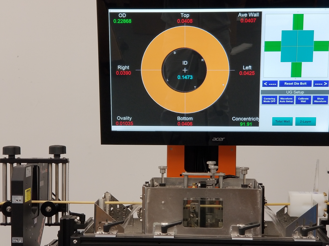
Outside diameter alone cannot reveal whether the lumen is centered or whether one side of the tube is thin. UltraGauge uses ultrasonic pulse-echo principles to detect acoustic interfaces and calculate wall thickness at configured paths. LaserLinc positions the technology for real-time wall thickness, concentricity, and ID workflows and notes that adding a Triton laser micrometer provides a fuller cross-section including OD and ovality.[4]
The exact transducer arrangement should not be generalized as “always four” or “always eight.” Transducer frequency, aperture, count, angle, working distance, and position depend on OD, wall range, material, acoustic velocity, interface quality, line motion, and the dimensions that must be reported. AutoPilot can automatically position the transducer assembly to improve alignment during startup and changeovers, but feasibility still begins with the actual tubing samples and range.[4]
Strong applications
- Inline wall thickness and wall balance
- Die-centering feedback during startup
- Calculated ID when paired with synchronized OD
- Polymer and suitable metallic tubing
- Continuous trend and alarm data
- Closed-loop wall control where the process permits it
Feasibility questions
- Will sound propagate cleanly through the material?
- Can each required interface be resolved?
- Is the tube centered and stable in the measurement zone?
- Are multiple layers or lumens acoustically separable?
- Does the calibration account for material and temperature?
- How will OD and wall records be matched by length?

03FlawSense for continuous surface-defect and contour inspectionWhen the risk exists between the diameter axes
A clean OD trend can coexist with a scratch, pit, blister, wrinkle, crack, or localized surface event. Diameter gauges observe a limited number of projected directions. FlawSense instead uses laser-line triangulation to build a continuous contour map around the outside of the product. LaserLinc states that the system measures 100 percent of the product surface and supports defect visualization by location, shape, and severity.[5]
This is particularly useful when manual inspection is inconsistent, the product moves too quickly for reliable visual review, or defects are discovered only after braiding, printing, assembly, sterilization, or packaging. FlawSense can also provide contour-based dimensional information that is not dependent on tube orientation in the same way as fixed-axis shadow measurement.
Good candidates
- Pits, scratches, cracks and slits
- Blisters, bubbles, gels and inclusions that disturb the surface
- Wrinkles or braid-related contour changes
- Localized lumps and neckdowns
- Full-surface diameter or shape analysis
- Automated sorting, marking, alarms or data review
What it does not prove
- Internal lumen geometry
- Subsurface voids that do not affect the surface
- Bond, weld, pull or burst strength
- Material chemistry or biocompatibility
- Every cosmetic condition unless the acceptance rule is defined
- Process capability without an appropriate study

04Bump, taper, transition and in-process profile measurementMeasure changing geometry as a feature, not as random OD noise
Many catheter shafts and medical extrusions are intentionally nonuniform. They may include tapers, bumps, necked sections, transition zones, balloons, radiopaque marker regions, or changing stiffness constructions. A conventional OD alarm can treat the intended feature as a defect unless the software knows the profile that should be present.
LaserLinc introduced an in-process bump-and-taper solution using a virtual ring-gauge concept to identify feature transitions, dimensions, and lengths during production. The value is not simply another diameter number. It is the ability to associate a changing profile with location, recipe, and acceptance logic while the part is being made.[8]
Define the feature
- Baseline and feature diameters
- Transition start and end criteria
- Feature length and slope
- Permitted overshoot or undershoot
- Triggering, encoder, or recipe logic
- Whether the feature repeats continuously or by part
Choose the workflow
- Inline feedback during extrusion
- Post-process scan of finished shafts
- Both inline control and offline verification
- Surface mapping where shape is not axisymmetric
- Sample retention and report requirements
- Sorting or cut-position output
For a simple axial taper, a laser micrometer and encoder may be enough. For more complex shape or surface risk, FlawSense or a Metron platform may be the better measurement layer. The application should be defined by the feature that must be accepted, not by the product name alone.
Back to technology guide ↑05BenchLinc for repeatable cut-sample and rigid-tube inspectionMove beyond hand tools without forcing every part into one fixture
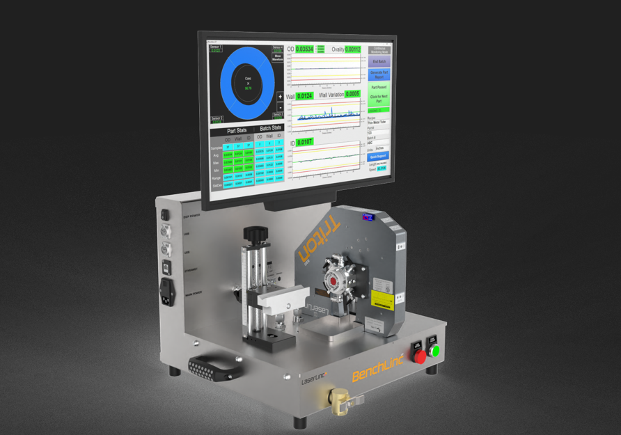
Offline inspection is not one category. A short flexible polymer sample, a rigid hypotube, a mandrel-loaded catheter shaft, and a coil of longer tubing all require different handling. LaserLinc offers multiple BenchLinc configurations rather than one universal bench gauge. The sample-inspection family includes manual OD/ovality checks, automated rotational OD inspection, OD/ID systems using dedicated mandrels, and ultrasonic configurations for wall thickness and concentricity.[6]
BenchLinc OD/ID is useful when short cut samples need automated OD, ID, wall, and ovality results under a controlled method. BenchLinc UT applies ultrasonic measurement to suitable rigid, metallic, mandrel-loaded, or cut-to-length tubing, with an optional Triton micrometer to add OD and ovality. The correct choice depends on part stiffness, sample length, whether the lumen can accept a mandrel, wall range, and the amount of automation required.

06Metron for automated full-length scanningProfile the entire catheter, guidewire, shaft or long precision part
A few spot measurements cannot describe a long taper, repeated transition, full catheter shaft, guidewire, mandrel, or other length-dependent product. Metron is LaserLinc’s automated sample-inspection platform for scanning a defined profile with laser, ultrasonic, or FlawSense technology. It can verify dimensions of interest, identify defects, accept or reject, log data, and report through an operator-defined workflow.[6]
Part handling is as important as the sensor. A long flexible part may need controlled tension, straightening, guides, or a vertical presentation. A rigid part may need supports that do not bend it. The scan must also distinguish product geometry from fixture-induced movement, sag, curl, or runout.
Common Metron objectives
- Full-length OD and taper profile
- Transition location and length
- Guidewire, mandrel and catheter shaft inspection
- Automated pass/fail and reporting
- R&D comparison of prototypes
- Post-process verification of inline data
Application inputs
- Overall part length and diameter range
- Flexible, semi-rigid, or rigid construction
- Required scan speed and point spacing
- Feature map and tolerances by axial zone
- Part presentation and operator workflow
- Need for wall, surface, or OD technology

07Total Vu data, reporting and process controlMeasurement becomes useful when the right people can act on it
Total Vu is the common visualization and workflow layer across many LaserLinc systems. It can bring together Triton and Axion micrometers, UltraGauge wall measurement, FlawSense inspection, sample inspection, trends, SPC, reports, recipes, communications, and optional feedback-control functions.[7]
The first design question should not be “How many screens can the software display?” It should be “What decision must the operator, process engineer, quality engineer, and automation system make from the data?” A useful medical extrusion interface separates immediate control variables from release data, highlights the controlling limit, preserves context by recipe and lot, and avoids burying the operator in every possible channel.
Operator layer
- Current dimensions and tolerance status
- Cross-section or contour visualization
- Simple startup and changeover recipes
- Actionable alarms rather than alarm floods
- Trend windows matched to process delay
- Clear manual / automatic control state
Quality and engineering layer
- SPC, Cpk/Ppk and longer-term trends
- Run, lot, recipe and operator context
- Configurable reports and data export
- Correlation to offline verification
- Industrial communications and enterprise connection
- Controlled configuration and documented validation

08Calibration, measurement-system analysis and validationProve that the complete workflow is fit for its intended use
A high-resolution display is not evidence that the entire measurement process is capable. Validation should cover the complete system: sensor, electronics, software, calibration standards, fixtures, sample condition, environment, product presentation, operator method, data transfer, calculations, and decision rules.
NIST defines metrological traceability through a documented, unbroken chain of calibrations, with each link contributing to measurement uncertainty.[11] Traceability is important, but it is not the same as low uncertainty or good Gauge R&R. A traceable calibration pin can still be used in a poor fixture, on a dirty gauge, with an unstable product, or with a method that does not represent production.
Minimum study elements
- Intended feature being measured and acceptance rule
- Bias across the actual product range
- Short-term repeatability
- Operator or setup reproducibility
- Linearity, stability and environmental effects
- Correlation between inline and offline methods
Medical quality context
- Calibration and maintenance procedures
- Recipe and software version control
- Data capture and report verification
- Alarm, reject and control challenge tests
- IQ/OQ/PQ or equivalent validation approach
- Risk-based revalidation after meaningful changes
The FDA Quality Management System Regulation became effective February 2, 2026 and incorporates ISO 13485:2016 by reference. Those frameworks require manufacturers to establish and maintain an appropriate quality management system; they do not “approve” a particular laser, ultrasonic, or surface-inspection gauge.[9][10] ISO 10555-1 is one example of a product-family standard for sterile single-use intravascular catheters, but applicable requirements depend on the actual device and intended use.[13]
Common medical tubing materials and constructions
The same gauge head can behave differently when the material, temperature, wall structure, flexibility, or surface changes. These examples are selection considerations, not universal process settings.
Moisture control and thermal history can change extrusion stability. Laser shadow measurement is not limited by color or transparency, while ultrasonic calibration and interface resolution should be confirmed for the grade, wall, and temperature.
Soft or tacky tubes can be distorted by contact gauges and aggressive guides. Non-contact measurement is valuable, but presentation, vibration, water removal, and elastic recovery still matter.
Clear, tinted, or opaque PVC can be measured optically by the outside silhouette. Surface degradation, plate-out, gels, and thermal sensitivity may show up as dimensional or surface trends that require process diagnosis.
Flexible polyolefin tubing can wander or flatten before fully cooled. Gauge location, gentle support, internal air, and the difference between hot and finished dimensions deserve attention.
A gauge placed close to a hot process needs suitable environmental protection and a validated relationship to the cooled dimension. Do not copy the calibration or placement from a low-temperature polymer.
Transparency is not a barrier to shadow-based OD measurement, but high-temperature extrusion, surface finish, material motion, and acoustic behavior can affect the overall system architecture.
Very compliant tubing benefits from non-contact outside measurement. Curing state, tack, vibration, ovality, and fixture forces are especially important when comparing inline and offline results.
An acceptable outside diameter does not prove each layer, lumen, braid position, or wall segment. Ultrasonic feasibility depends on whether the required interfaces can be separated; complex structures may need multiple complementary methods.
Closed-loop control: useful, but not magic
Closed-loop control works when a reliable measurement is paired with an actuator that has a predictable and timely effect on the controlled characteristic. Total Vu includes feedback-control tools and industrial connectivity, but the control strategy must be engineered around the extrusion process.[7]
Puller speed, output, and sometimes internal air can influence OD. Choose one primary manipulated variable and document how other loops interact.
Wall responds to the relationship between mass output, line speed, OD, drawdown, and internal geometry. Direct wall feedback is stronger than inferring wall from OD.
Concentricity is often corrected through die centering, thermal balance, tooling, and flow distribution. A fast automatic downstream loop may not have the right actuator.
Defect data can trigger alarms, sorting, marking, or containment. It may also identify upstream patterns, but it does not always provide a direct continuous control variable.
Transport-delay and same-point correlation calculator
When two gauges are separated on the line, the software must associate their readings with the same physical location on the tube. Enter the station spacing and line speed to estimate the delay.
At 60 ft/min, tubing takes approximately 12 seconds to travel 12 feet between measurement stations.
Build evidence, not just data
Medical tubing measurement supports a quality system only when the intended use, method, uncertainty, validation, and records are defined. FDA’s QMSR became effective February 2, 2026 and incorporates ISO 13485:2016 by reference.[9][10]
State exactly whether the result is average OD, axis-specific OD, estimated ovality, minimum wall at measured paths, calculated ID, contour defect, or another characteristic.
Use standards and representative products across the validated operating envelope, not only one convenient nominal part.
Evaluate repeatability, reproducibility, bias, linearity, stability, fixture effects, product handling, and operator workflow.
Inline and offline data should be compared by physical location, temperature, conditioning, and measurement definition.
Recipes, calculations, filters, alarms, reports, permissions, communications, and control logic all belong inside the validated configuration.
Use documented calibration standards and an unbroken calibration chain while understanding the uncertainty at each link.[11]
An alarm is useful only when operators know what to verify, contain, adjust, document, and escalate.
Meaningful sensor, software, fixture, product, range, or control changes should trigger a documented impact assessment.
What I would avoid when specifying a medical tubing system
A centered thick wall and an off-center thin wall can produce the same outside diameter. Use direct wall information when wall or lumen geometry matters.
The laser sees the outside silhouette. ID is calculated only when synchronized wall data and a valid geometry model are available.
A wet optical station can generate false spikes and unstable dimensions. Design the air wipe and spacing as part of the gauge system.
Use the model-specific rate and the per-axis rate, then convert it to distance between samples at the actual line speed.
A fixed delay can associate different physical locations when line speed ramps. Encoder-based length correlation is stronger when exact point matching matters.
Concentricity often reflects tooling alignment, die centering, thermal balance, and material flow. First confirm there is a suitable actuator and controllable relationship.
Complex interfaces can overlap or disappear acoustically. Test the exact construction rather than extrapolating from simple single-lumen tubing.
A gauge can support a validated quality workflow, but compliance belongs to the manufacturer’s complete quality system and intended use.
Related Gauge Advisor tools and guides
This article is the system-level overview. Use these resources to go deeper into the exact dimension, workflow, technology, or business case.
Medical tube extrusion measurement FAQ
What should be measured on a medical tubing extrusion line?
The answer depends on the device requirement. Common characteristics include outside diameter, ovality, wall thickness, inside diameter, concentricity, taper or feature length, and surface defects. No single sensor automatically proves all of them.
Can a laser micrometer measure medical tubing ID and wall thickness?
Not directly. A laser micrometer measures the outside silhouette. ID can be calculated when valid wall-thickness data is synchronized with OD at the same tube location. Direct wall measurement normally requires ultrasonics or an appropriate offline method.
When is triple-axis measurement worth it?
Triple axis is usually the strongest fixed-axis choice for critical round or elliptical tubing when average OD, estimated ovality, rotation, product wander, or closed-loop control performance matter. A one- or two-axis configuration may still be the better fit for another geometry, range, or measurement objective.
Can ultrasonics measure transparent and opaque tubing?
Optical transparency is not the deciding factor for ultrasonics. The material must transmit sound and produce resolvable reflections at the required interfaces. Material, temperature, wall range, layer structure, transducer selection, and positioning all affect feasibility.
Can UltraGauge measure every lumen in multi-lumen tubing?
Not automatically. Complex lumen and layer geometries can create overlapping acoustic paths. Representative sample testing is required to determine which interfaces and wall segments can be measured reliably.
What is the difference between a laser micrometer and FlawSense?
A laser micrometer measures projected outside dimensions from one, two, or three directions. FlawSense maps the complete outside contour for full-surface defect and shape inspection. The correct choice depends on whether the requirement is dimensional control, full-surface quality, or both.
Should medical tubing be measured inline or offline?
Often both. Inline systems reveal process drift while the tube is being made. BenchLinc or Metron systems verify cut samples or finished-part profiles under a controlled QA method. The two workflows should be correlated rather than treated as interchangeable.
Can the measurement system automatically control the extrusion line?
It can support closed-loop control when the measured variable has an appropriate actuator, transport delay is handled correctly, the process is stable, and the loop is safely tuned. OD, wall, internal air, output, and puller speed interact, so the control architecture must be application-specific.
Is a LaserLinc system FDA compliant?
No measurement system is “FDA compliant” in isolation. LaserLinc equipment can support measurement, documentation, reporting, and validated workflows, but the medical-device manufacturer is responsible for the complete quality system, validation, procedures, training, records, and intended use.
What information is needed for a medical tubing measurement application review?
Useful inputs include material and layer structure, minimum and maximum OD, ID and wall ranges, tolerances, line speed, product temperature and condition at the proposed station, surface-defect concerns, part length, inline or offline workflow, data requirements, control goals, installation space, and representative samples.
References
The product-specific sources are official LaserLinc materials. The regulatory and metrology sources are independent public authorities and standards organizations rather than competing equipment suppliers.
- LaserLinc, “Solutions.” Overview of laser micrometers, ultrasonics, defect detection, sample inspection, and Total Vu.
- LaserLinc, “Triton: Three-Axis Laser Micrometers.” Official product positioning for round and elliptical products, average diameter, and estimated ovality.
- LaserLinc, “Axion: One- and Two-Axis Laser Micrometers.” Official product positioning for rectangular profiles, fit-for-purpose measurement, and constrained applications.
- LaserLinc, “Ultrasonic Measurement.” Official UltraGauge and AutoPilot overview for wall thickness, concentricity, and combined tube-profile measurement.
- LaserLinc, “Defect Detection.” Official FlawSense overview for full-surface mapping, defect detection, and contour measurement.
- LaserLinc, “Sample Inspection.” Official Metron and BenchLinc overview for automated and benchtop verification.
- LaserLinc, “Process Visualization.” Official Total Vu overview for visualization, analysis, documentation, integration, and control.
- LaserLinc, “Are Your Measurement Systems Working Together?” Integrated inline and post-process measurement strategy.
- U.S. Food and Drug Administration, “Quality Management System Regulation (QMSR).” Effective February 2, 2026; incorporates ISO 13485:2016 by reference.
- International Organization for Standardization, ISO 13485:2016, “Medical devices — Quality management systems — Requirements for regulatory purposes.”
- National Institute of Standards and Technology, “Metrological Traceability: Frequently Asked Questions and NIST Policy.”
- ASTM International, ASTM E797/E797M, “Standard Practice for Measuring Thickness by Manual Ultrasonic Pulse-Echo Contact Method.” General ultrasonic thickness-measurement context.
- International Organization for Standardization, ISO 10555-1:2023, “Intravascular catheters — Sterile and single-use catheters — Part 1: General requirements.”
Build the right measurement stack for your medical tubing line
Gauge Advisor is the authorized LaserLinc sales and applications support partner. I help medical tubing manufacturers select, quote, integrate, and support LaserLinc laser micrometers, UltraGauge wall-measurement systems, FlawSense surface inspection, BenchLinc, Metron, and Total Vu.
Gauge Advisor supports equipment selection and integration for the manufacturers represented here; independent process consulting is not offered. I will respond within one business day, often within a few hours.
- Material and layer or lumen construction
- Minimum and maximum OD, ID and wall ranges
- Tolerances and critical release characteristics
- Line speed, product temperature and gauge location
- Inline, short-sample or full-length workflow
- Surface defects, profile features and reject logic
- SPC, reporting, communications and control goals
- Photos, drawings and representative samples when available