
Automatic Thickness Profile Control for Cast Film & Sheet
Measure thickness across the web and use that profile to adjust the die automatically. For cast film and sheet, Scantech combines a suitable scanner, FlexScan software and automatic mapping with a compatible flat die. Scantech Bolt Controller 3 (BC3) controls compatible thermal die bolts.
Flat-die control focus: This page covers cast film and sheet lines with a compatible automatic or retrofit die. Blown film uses a different arrangement for measurement and thickness correction.

When operators can see thickness variation but struggle to correct it
Automatic profile control is not simply another scanner option. It becomes valuable when cross-web variation, startup behavior and manual die adjustment are creating repeatable production losses that a compatible die can actually correct.
Persistent cross-web variation
Center-heavy, edge-heavy or repeating profile patterns remain after the average thickness reaches target.
Slow startup and changeover
Operators wait through repeated scans and manual bolt corrections before the profile is ready for production.
Shift-to-shift dependence
Profile quality depends on which operator is interpreting the scan, choosing a bolt and judging how much to adjust.
An automatic die is underused
The line already has thermal bolts or supported actuators, but measurement, mapping or closed-loop control is incomplete or obsolete.
Connect each position on the measured profile to the die zone that can adjust it
The loop must preserve the relationship between the measured web, die position, process delay, actuator response and the next profile used to verify the result.
Measure the moving web
An application-matched Scantech channel traverses the usable width.
Build the cross-direction (CD) profile
FlexScan builds the cross-direction profile while separately trending machine-direction average movement.
Map web to die
Automatic assignment aligns measured positions with physical die bolts or zones.
Calculate correction
APC applies the qualified control model, limits and interaction rules.
Adjust the die
For compatible thermal dies, BC3 regulates qualified bolt power and temperature. Supported motorized or robotic dies use the project-approved Scantech actuator interface.
Verify and regulate
Later scans show the response and continue controlled correction toward target.

BC3 addresses cross-direction profile shape through the die. A separate machine-direction loop may act on approved extruder, melt-pump, line-speed or chill-roll signals to regulate the average. The two loops must not be treated as interchangeable.
Why Scantech low-energy X-ray is often the strongest BC3 input for cast film
The X-ray head does not correct the die. It supplies the cross-web error signal that FlexScan maps and BC3 acts upon. A responsive, repeatable and well-resolved profile can support finer corrections and tighter regulation when the recipe, process delay and die response are commissioned correctly.
Stable total-web profile across thin, colored and optically changing films
For many cast film lines, Scantech low-energy X-ray provides a basis-weight or calibrated-thickness profile across the full measured width, including the edge regions needed for accurate die mapping. Its electrically generated source avoids the half-life deterioration and end-of-life source burden associated with beta or gamma gauges.
Why this can tighten BC3 control: cleaner profile information and dependable edge mapping give APC a more useful error signal. That supports smaller, more confident corrections and reduces the risk that profile noise or position error becomes an unnecessary die-bolt move.
Scantech low-energy X-ray
Strong for total basis weight and calibrated thickness across many transparent, opaque, colored and very thin films. The repeatable, well-resolved profile and edge coverage create a strong input for automatic mapping and BC3 correction.
Confirm: attenuation still depends on material composition, density, fillers, layers, energy and the approved calibration recipe.Beta transmission
Beta gauges can provide accurate mass-per-area profiles and have a long industrial history. For modern cast film projects, the sealed source introduces half-life, licensing, handling and eventual disposal considerations that electrically generated X-ray avoids.
Modern beta systems can be responsive and precise. Performance and lifecycle fit depend on the source, detector, integration, mechanics, calibration program and site requirements.Gamma transmission
Gamma transmission is generally better suited to thicker or more attenuating products that require greater penetration. On lightweight cast film, properly selected low-energy X-ray typically provides more useful sensitivity without a sealed isotope source.
Confirm: gamma remains viable where the product range and required penetration justify it; source, detector, geometry, regulatory program and control response still require review.Infrared
Infrared can be excellent for selected polymers, barrier layers, coatings, moisture or composition. Because spectral absorption changes with formulation and layer structure, it often requires application-specific calibration and may be better suited to a constituent-specific measurement than a universal total-web signal.
Use when: the selected absorption band directly represents the layer, constituent or property the process must control.Why this system can outperform common alternatives: For many cast film BC3 projects, low-energy X-ray is a strong general-purpose total-web input because it combines thin-film sensitivity, full-width edge-aware mapping, relative insensitivity to optical appearance and non-isotope operation. Beta remains viable, gamma fits higher-attenuation duties, and IR may be better for a selected constituent or layer. Final selection still requires product, calibration, scan-time and die-response qualification. For a deeper explanation of the measurement physics, review X-Ray Transmission Web Gauging.

BC3 turns the mapped profile into controlled die-bolt action
Scantech publishes Bolt Controller 3 as the automatic die-bolt control hardware for a fully engineered profile loop. FlexScan/APC supplies the mapped control logic; BC3 manages qualified bolt power and temperature and supports detection of heater failures.
- APC is a separate engineered option, not an automatic feature of every scanner
- BC3 thermal-bolt control, and any separate stepper-motor or robotic-actuator interface, require application confirmation
- Cabinet, voltage, connectors, channels, limits and safe states belong in the approved drawings
Measurement technology stays application-specific. Cast film often starts with low-energy X-ray, while very thick sheet or a direct-geometry requirement may use another qualified channel. APC is not an X-ray-only system.
FlexScan displays the process. TREX retrieves production reports.
The control loop needs live profile and bolt visibility. Production and quality teams also need to retrieve what happened across a roll, recipe, customer order or alarm period after the line has moved on.
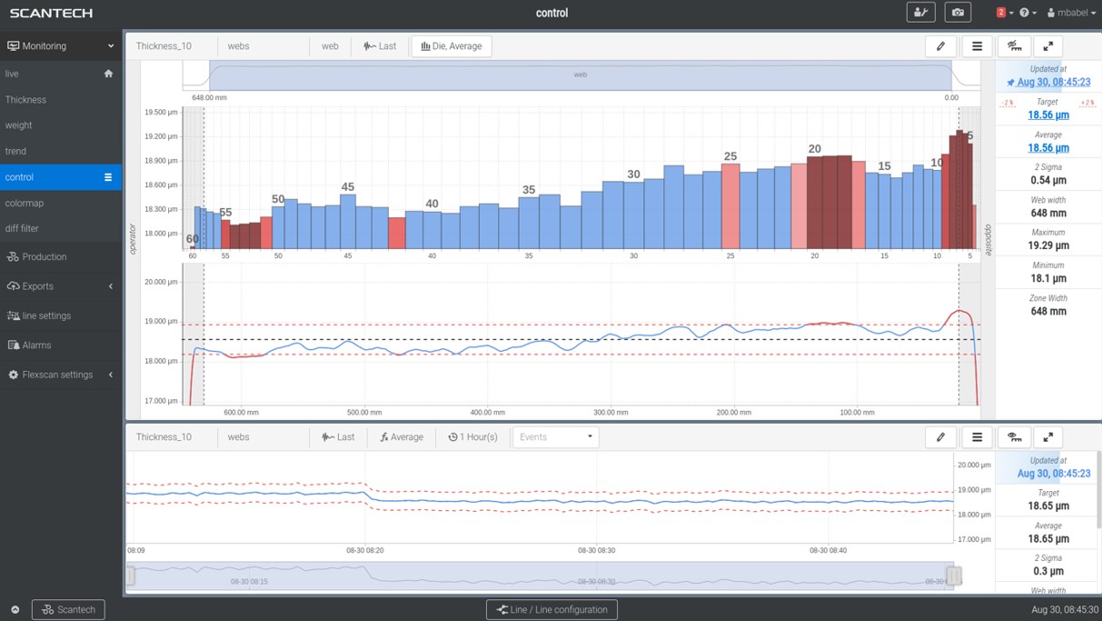
See the profile, mapped bolts and process response together
The live control view connects the cross-web profile to numbered die locations while trends, targets, limits and status help operators understand whether the loop is correcting the right problem.

Retrieve profiles and production records after the roll is complete
TREX organizes archived production information for retrieval through configured tags such as recipe, customer or production identifier. Roll reports, average profiles, trends, statistics, events and alarms can support quality review and responses to customer questions.
Define the record before commissioning. Agree on valid-data rules, edge exclusions, product tags, retention period, report fields, users, export and plant-network responsibilities instead of treating historian setup as a final software preference.
Scantech experience spans cast film, sheet and demanding biax film measurement
Automatic die control is strongest when it sits inside a measurement platform already built around flat-web scanning, wide-film mechanics, profile interpretation, production data and process integration.

One flat passline can connect the measured profile directly to the upstream die
A stable single web allows the scanner to build a full cross-direction profile. With compatible actuators and a qualified map, the system can regulate local die zones while a separate loop manages the average.
- Measurement, alarms and roll reporting
- Automatic mapping and BC3 profile correction
- Independent MD average-control review

Wide films and multiple process stages need a stable wide-web measurement system
For biax film and other orientation processes, HF3 is a strong wide-web frame starting point when the line width and mechanical demands exceed compact-frame territory. Measurement before and after stretching can help separate the incoming cast-sheet profile, stretch response and final-roll quality. Final scanner family and control opportunity depend on measured width, passline, process stage, line speed and the upstream actuator.
- HF3 wide-web mechanics and profile timing
- Pre- and post-orientation measurement options
- TREX history and final-roll evidence
Do not force one system onto every film line. Cast film, flat sheet, MDO and biax processes can place the scanner at different stages and may need one or multiple stations. Final control scope follows the point where the measured variation can still be corrected.
Choose monitoring, operator-guided adjustment or automatic control
A Scantech scanner does not automatically include BC3 or closed-loop die correction. Select the measurement, guidance and control level the line can support and the production team will use.
Measurement and reporting
The scanner builds profiles, trends, alarms and roll records. Operators or engineers decide what process action follows.
Best fit: visibility, QA evidence and process diagnosis.
Operator-guided adjustment
The system presents the mapped profile and die locations so the operator can make a controlled manual or assisted correction.
Best fit: lines that are not ready for automatic actuation.
Automatic profile control
APC regulates a compatible automatic die from the mapped cross-direction profile. BC3 is the control system for qualified thermal bolts; supported motorized or robotic actuators require their approved interface.
Best fit: repeatable variation that the die hardware has enough adjustment range to correct.
Average-thickness control
A separate loop uses the qualified average to act on an approved extruder, pump, line-speed or chill-roll command.
Boundary: MD control does not flatten a local CD profile.
Build the control scope around the actual die, not a generic bolt count
Gauge Advisor has worked on projects involving die and line equipment from Cloeren, MAAG, Nordson EDI, maku, JCTIMES and others. For each new or retrofit control project, Gauge Advisor coordinates the Scantech measurement-and-control scope around the actual equipment. These names indicate project experience; they do not imply a formal partnership or universal plug-and-play compatibility.
Compatibility is confirmed project by project. The review covers the die model, actuator type, bolt count and spacing, heater load, connectors, cabinet, drawings, existing controls and the responsible party for each interface.
Six interfaces determine whether the loop can work
Share the line details needed to match measurement and die control
Send the same information whether the project replaces an obsolete controller, adds control to an existing scanner, pairs Scantech with a new automatic die, or scopes a complete scanner and BC3 package.
Material and quality target
Define what the scanner must measure and what release actually requires.
- Structure, resin, filler, PCR and density
- Nominal, minimum and maximum thickness
- Current CD spread, edge rules and lab method
Die and actuator details
Document the hardware that will make the correction.
- Manufacturer, model, lip width and drawings
- Bolt count, spacing and actuator type
- Heater voltage, wattage and connector details
Measurement location
Confirm the web presented to the scanner is stable and representative.
- Web width, deckle, passline and opening
- Line speed and die-to-scanner distance
- Temperature, flutter, access and service space
Existing control system
Identify what stays, what changes and what system owns each signal.
- Present scanner, controller, PLC and HMI
- I/O, network, OPC UA and line interlocks
- Manual, assisted, APC and MD-control modes
Losses worth correcting
Quantify the problem without inventing a universal savings percentage.
- Startup and changeover scrap
- Material giveaway and out-of-spec rolls
- Operator adjustment time and customer claims
Performance checks and responsibilities
Agree on the test method and how control performance will be evaluated.
- Recipes, samples and reference correlations
- FAT, SAT, tuning and production trial
- Limits, safe states, reports and training
Turn a profile display into repeatable production action
Results depend on the starting process, die condition, available adjustment range, measurement quality and commissioning. Agree on the performance checks for your line and verify the results during commissioning.
Less startup and changeover scrap
Move from repeated manual adjustments toward a controlled correction sequence and reusable recipes.
Tighter cross-web profile
Use mapped local corrections for local variation rather than changing only the average output.
More consistent operator response
Reduce reliance on individual judgment about which bolt to change and how long to wait.
Clearer records for each roll
Connect live control behavior with TREX profiles, production history, tags, events and reports.
Mechanical and thermal instabilityAPC cannot repair a damaged or fouled die, unstable melt delivery, severe temperature drift, vibration or web presentation problems.
Insufficient die adjustment rangeThe loop cannot correct a profile shape that exceeds the available bolt range, response speed or physical influence on the melt.
Wrong measurement modelA control loop cannot overcome an unsuitable sensor, incomplete calibration, changing composition or invalid edge and profile data.
Explore web gauging systems and film and sheet measurement
Use Web Gauging Systems to compare scanners, measurement options and software. Use Film & Sheet Measurement when the problem may also involve extrusion, blown film equipment or web handling.
Web Gauging Systems
Review scanner frames, measurement technologies, FlexScan HMI choices, TREX reporting, plant integration and optional control as one production system.
Explore complete web gauging → Extrusion process overviewFilm & Sheet Measurement
Connect Scantech profile measurement with cast film, sheet, biax and blown film process decisions across the wider Gauge Advisor offering.
Explore film and sheet solutions →Share the measurement and die details for your control project
A preliminary review can begin with drawings, photos, screenshots and current production records. Final selection and performance terms remain with Scantech’s written application review and quotation.
Product structure
Resins, layers, fillers, density, PCR, color, thickness range and accepted reference.
Web and passline
Maximum measured width, line speed, deckle, scanner location, temperature and access.
Die details
Supplier, model, drawing, lip width, bolt count, spacing and present actuator condition.
Electrical data
Heater or actuator voltage, wattage, connector, cabinet and available documentation.
Existing controls
Scanner, HMI, PLC, controller, I/O, network, interlocks and system ownership.
Current profile
Representative scans, edge exclusions, target, tolerance, recipes and operator actions.
Production loss
Startup scrap, changeover time, giveaway, downgraded rolls and customer evidence.
Data and acceptance
TREX tags, reports, retention, FAT, SAT, tuning, training and desired project timing.
Automatic profile control questions
What is automatic thickness profile control?
What does Scantech Bolt Controller 3 (BC3) do?
Does BC3 control both the profile and average thickness?
Can automatic profile control be retrofitted to an existing die?
Has Gauge Advisor worked with Cloeren, MAAG, Nordson EDI, maku or JCTIMES equipment?
Why is low-energy X-ray often a strong input for BC3?
Does automatic profile control require an X-ray scanner?
Where do FlexScan and TREX fit?
Does this page also cover blown film gauge control?
What problems can automatic profile control not fix?
Start with one current profile, the die drawing and the correction you want production to make
Share your line and product details, current profile and die information. Gauge Advisor will help clarify the measurement and control requirements, coordinate Scantech’s technical review, and prepare the project for quotation.
Equipment project inquiries welcome worldwide. Gauge Advisor reviews your application and coordinates the next step with Scantech.
- Current profile or HMI screenshot
- Die and actuator drawings
- Web width, speed and scanner location
- Existing PLC, I/O and control scope
- TREX, reporting and acceptance needs