Updated August 21, 2026
An e-coat line can look stable until the cured film is measured and a cavity entrance, sharp edge, welded flange, rack-adjacent area, or mixed-metal feature falls below the plant’s approved window. This guide explains how to measure e-coat thickness before and after bake, how to correlate the two process states, and how to choose repeatable inspection points without pretending that a few readings represent an entire vehicle or assembly. AIM Systems lists E-Coat / EPD on aluminum and steel—before and after baking or cross-linking—as a validated application for its CoatPro photothermal system.[2] AIM develops and manufactures the technology in Germany; Gauge Advisor is AIM Systems’ North American sales and applications representative.
Connected process path: Use before-bake measurement to catch deposition problems early, then compare the baked result with the coating requirement and process capability.
Related next steps: e-coat thickness measurement systems, photothermal coating thickness measurement, point and area coating measurement, coating weight and thickness calculator, and coating measurement ROI calculator.
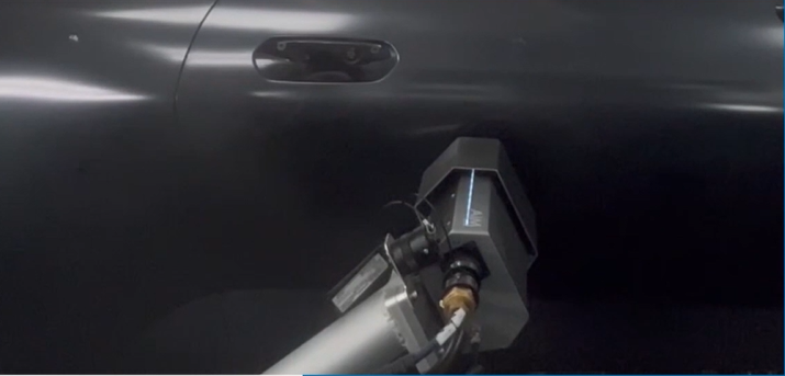
Measure the same risk-based locations in two clearly defined process states
For an e-coat process, “before bake” and “after bake” are not interchangeable labels for the same measurement.
Electrocoating is a system, not just a dip tank. A representative sequence includes pretreatment, electrodeposition, post-rinses, and a cure oven.[4][5] A plant may place CoatPro before the oven, after the oven, or at both stations. The right layout depends on whether the measurement must prevent value from entering the bake cycle, confirm final dry-film thickness, or create a paired data model for process control.
Earlier feedback on deposited build at defined locations. The film is uncured and should not be contacted.
Final physical build after the approved cure and cooling condition. Feedback arrives later.
Matched pre- and post-bake locations reveal the actual relationship for that recipe, substrate, geometry, and oven.
Cure, adhesion, corrosion, appearance, and edge durability need their own approved tests.
E-coat, electrocoat, EPD, CED, and KTL usually point to the same process family—but not the same specification
Search language varies by company and region. North American plants most often use “e-coat” or “electrocoat.” Engineers may also use electrophoretic deposition (EPD), cathodic electrodeposition (CED), electro-deposition, or KTL.
What this article measures
Organic e-coat on metalA protective electrophoretic coating on conductive steel or aluminum parts, measured after final rinse before bake or after cure. AIM’s validated list names both substrates and both process states.[2]
- Typical roles
- Automotive primer, single protective coat, corrosion-control layer beneath powder or liquid topcoat.
- Output
- Coating thickness at selected, calibrated locations.
- Architecture
- Fixed CoatPro point, multiple fixed sensors, or robot-guided sequence.
What it does not measure by itself
Keep the measurands separateA thickness result is not bath chemistry, cure state, edge continuity, surface-defect detection, corrosion life, or adhesion. It also is not the total thickness of later primer, basecoat, clearcoat, or powder layers unless the complete stack has been separately validated.
- Different layer
- Conversion coating or pretreatment weight beneath the e-coat.
- Different test
- Oven profile, solvent resistance, tape adhesion, hardness, salt spray, cyclic corrosion, or appearance.
- Different geometry
- A complete vehicle body is not one camera frame or one point.
Electrocoat is already a real North American production process—not a speculative European-only application. PPG documents high-volume e-coat service in Fort Wayne, Indiana for automotive, commercial, agricultural, and heavy-truck markets, including mixed-metal parts; its Cambridge, Ontario facility runs two monorail e-coat systems and serves automotive, agriculture, industrial, furniture, recreational, truck, and bus customers.[6][7] Those facilities are cited to establish the U.S. and Canadian manufacturing footprint; they are not measurement-equipment competitors.
Before-bake thickness is an early control variable; after-bake thickness is the cured-film result
They can be strongly related without being numerically interchangeable.
| Decision | After final rinse, before bake | After bake and controlled cooling | Engineering consequence |
|---|---|---|---|
| What is being measured? | An uncured, physically soft coating in a defined rinse/drain/temperature condition. | The cured film after the specified part-temperature history and cooling condition. | Use separate, named calibrations and never mix the populations in one control chart. |
| Why measure here? | Find deposition drift before oven energy and more downstream value are added. | Confirm the final dry-film build required by the drawing, process specification, or customer plan. | Choose the station from the decision the number must support—not from sensor convenience. |
| What can change? | Drain time, residual rinse water, surface temperature, handling, deposition distribution, and film condition. | Flow, leveling, cross-linking, volatile removal, edge recession, oven variation, and cooling.[17] | Match location, recipe, substrate, pretreatment, hanger, and time-to-measure during correlation. |
| Can a contact probe be used? | A probe can deform or mark the uncured film; ASTM D7091 is fundamentally a dry-film contact-gauge practice and excludes readily deformed coatings from its normal procedure.[9] | Magnetic induction on ferrous substrates or eddy current on nonferrous conductive substrates may be suitable at accessible points. | Non-contact CoatPro opens a practical pre-bake measurement window while cured DFT still supports conventional reference checks. |
| Is the result final release? | Only if the customer-approved control plan accepts the qualified correlation and its uncertainty. | Usually the more direct thickness release state. | Keep periodic post-bake verification even after a pre-bake predictor is deployed. |
One reason matched measurements matter is geometry. Peer-reviewed automotive electrocoat research reports that a film can be adequate on a sharp edge during deposition, then recede during thermal baking as the coating flows, leaving lower thickness at the edge.[12] That does not mean every formulation behaves the same way; it means a center-panel reading before the oven cannot prove the cured edge condition.
See how four convenient points can pass while a risk-based CoatPro sequence finds the thin locations
Choose a representative steel assembly or aluminum housing, switch between pre-bake and cured measurements, and compare a four-point convenience plan with an eight-point risk-based sequence. The values and limits are synthetic; the visual teaches measurement strategy, not a universal e-coat specification.
22.1 µmMeasured / pass
20.6 µmMeasured / pass
—Not sampled
19.5 µmMeasured / pass
19.8 µmMeasured / pass
—Not sampled
—Not sampled
—Not sampled
20.2 µmMeasured / pass
18.7 µmMeasured / pass
—Not sampled
19.3 µmMeasured / pass
18.3 µmMeasured / pass
—Not sampled
—Not sampled
—Not sampled
All four selected cured-film points meet the synthetic 18.0 µm limit. The convenience plan does not inspect the cavity entrance or rocker end.
The lesson is not “always use eight points.” It is to use the smallest sequence that still covers the failure modes in the PFMEA, drawing, customer requirement, and historical defect data. A 2026 industrial CED study used predefined control stations to evaluate positional effects and process capability; its data also linked thickness variability to factors such as contamination, bath chemistry, and hanging configuration.[16] Your plan may need four points, forty points, parallel sensors, a robot path, or a separate engineering audit. Cycle time and risk—not a web illustration—set that number.
How AIM CoatPro measures e-coat without touching it
CoatPro is not measuring laser distance and it is not simply reading the surface temperature. It applies periodic optical excitation, detects the infrared response, and uses the phase relationship with an application-specific calibration to return coating thickness.
The coating must absorb enough excitation light and the coating-to-substrate interface must produce sufficient thermal contrast. AIM’s white paper explains why thermal properties, optical absorption, excitation frequency, measurement time, and the reference samples matter. It also notes that a coating may be more measurable in the wet or unbaked state when the baked state has weak thermal contrast.[3]
A periodically modulated LED creates a small thermal response without ionizing radiation.
The timing of the infrared response changes with the coating and interface.
Representative samples with independently assigned thickness values establish the valid relationship.
Coating chemistry, pigment, substrate, pretreatment, cure state, and range can change the response.
This validated e-coat application is CoatPro only—and a whole vehicle is a programmed point sequence, not one area scan
AIM’s current validated-application table names CoatPro for E-Coat / EPD. It does not list CoatPro XD for this application.[2]
AIM CoatPro

CoatPro fits the application when the important locations can be defined. A fixed sensor can check one repeatable location, multiple units can measure in parallel, or a robot can present the sensor to a programmed sequence across a part or vehicle body.
- Non-contact and suitable for wet or uncured coatings.
- Typical published range on the current product page: 1–1000 µm.
- Typical working distance: 100 mm with a stated 50 mm tolerance.
- Typical angular tolerance: ±75° for curved or tilted surfaces.
- Single-point, continuous, and robot-sequence modes.
- Power over Ethernet, Modbus TCP example integration, synchronized multi-sensor control, PNG and CSV export.
Best fit: Defined inspection points, repeatable robot paths, early pre-bake feedback, cured-film checks, mixed part families with controlled recipes, and production traceability.
All published values are typical and application-dependent. Sample testing establishes measurability, precision, measurement time, optical configuration, working geometry, and the final architecture.[1]
Best when one feature is a strong process indicator and every part presents it consistently after rinse and drain.
Best when several faces, edges, pockets, or part families must be checked with one sensor.
Best when cycle time makes sequential motion too slow and several points can be measured in parallel.
Best for final DFT verification, correlation maintenance, calibration checks, and periodic MSA.
What different before-and-after patterns suggest
The pattern is diagnostic evidence, not an automatic root-cause verdict. Confirm it against bath, rinse, part-temperature, pretreatment, racking, and defect data.
| Observed pattern | Most useful interpretation | What to investigate next | What not to conclude |
|---|---|---|---|
| Low before bake and low after bake at the same locations | A deposition or local-coverage problem becomes more likely. | Voltage/current history, electrical contact, bath chemistry, temperature, pretreatment, throwing power, geometry, rinse re-solving, hanger and part mix. | Do not increase voltage blindly; higher voltage can create other defects. |
| In range before bake, shifted or variable after bake | Oven profile, part temperature, flow, stoving loss, pre-bake condition, or state-specific calibration deserves attention. | Actual part-temperature/time, loading density, airflow, cooldown, drain interval, pooled water, calibration recipe, and matched-location residuals. | Do not call it under-deposition until the two measurement states are verified. |
| Same spatial pattern before and after bake | Geometry, current distribution, shielding, racking, or substrate/pretreatment differences are plausible common drivers. | Edges, cavities, weldments, mixed-metal areas, electrical contact, immersion orientation, and rinse drainage. | A repeatable pattern is not automatically an acceptable one. |
| Thickness in range but adhesion, cure, or corrosion fails | The film build is not the primary missing evidence. | Surface preparation, conversion treatment, contamination, oven cure, coating chemistry, discontinuities, and the complete coating-system test. | More thickness is not a universal corrective action. |
| Average passes but an edge or recess fails | The sampling plan or disposition rule is masking local risk. | PFMEA locations, local minimum rules, edge/burr protection, cavity access, point repeatability, and robot recipe. | A part-level mean does not prove every required location. |
A practical validation workflow for pre-bake and cured e-coat thickness
Automotive suppliers should connect the work to the customer drawing, PPAP/control plan, MSA, PFMEA, and the applicable coating-system assessment. AIAG’s CQI-12 emphasizes defect prevention and reduction of variation and waste in automotive coating management systems.[8]
Cathodic or anodic system, epoxy or acrylic family, color, supplier recipe, substrate, pretreatment, any zinc layer, and later topcoats.
Final DFT, local minimum, warning limit, pre-bake process signal, post-bake release, or correlation model. Record the governing document.
Flats, edges, stamping burrs, recesses, cavities, welds, drains, horizontal shelves, mixed-metal transitions, rack contacts, and known defect zones.
For pre-bake, define final-rinse exit, drain time, orientation, temperature, and pooled-water rule. For post-bake, define part-temperature profile and cooldown.
Use representative parts or coupons across the intended range. Assign independent values and document location, method, uncertainty, and traceability.
Evaluate absorption, thermal contrast, excitation, precision, measurement time, working distance, angle, motion, coating state, and range.
Measure the same parts and locations before and after bake across normal and intentionally shifted conditions. Review residuals by feature and recipe.
Challenge repeatability, reproducibility, fixture or robot presentation, temperature, recipes, reference checks, alarms, remeasurement, traceability, and containment.
CoatPro, contact DFT gauges, microscopy, and performance tests are complementary
The comparison is technology-level and contains no named measurement competitors.
| Method | Useful output | Strong fit | Important boundary |
|---|---|---|---|
| AIM CoatPro photothermalValidated e-coat application | Calibrated thickness at a defined point or along a programmed continuous/robot sequence. | Non-contact pre-bake measurement, automated repeatable points, curved or moving parts, parallel stations, production data. | Application-specific calibration and feasibility testing. It does not prove cure, adhesion, corrosion, or full-vehicle coverage. |
| Magnetic induction | Dry-film thickness of a nonmagnetic coating over a magnetic substrate. | Accessible cured e-coat on steel; lab or manual reference checks. ISO 2178 defines the tactile magnetic method.[10] | Contact method; edge, curvature, roughness, underlying metallic layers, probe placement, and soft film can affect use. |
| Amplitude-sensitive eddy current | Thickness of a nonconductive coating over a nonmagnetic conductive substrate. | Accessible cured e-coat on aluminum. ISO 2360 defines the method and its application boundaries.[11] | Contact point method; substrate conductivity, thickness, edge distance, curvature, roughness, and geometry matter. |
| Cross-section or microscopy | Local physical section view of layer build and interfaces. | Reference assignment, multilayer investigation, edge studies, failure analysis, and correlation development. | Destructive, local, sample-preparation dependent, and generally too slow for every production part. |
| Oven profile and cure test | Part-temperature history and an approved indicator of chemical/physical cure. | Confirming that the coating saw the specified time-temperature window and achieved the required cure response. | Not a coating-thickness measurement. ASTM D5402 also warns that solvent resistance alone does not prove full cure.[14] |
| Adhesion test | Application-specific adhesion rating or bond evidence. | Validating the coating/substrate/pretreatment interface. ASTM D3359 covers tape-test ratings on metallic substrates.[13] | Not thickness, and the tape method does not finely distinguish high adhesion levels. |
| Corrosion exposure | Performance of the substrate, pretreatment, coating, defect preparation, and exposure protocol as a system. | Qualification, comparative development, and customer-specific durability evidence. | Not thickness. ASTM B117 provides controlled salt-fog conditions and warns against simple field-life prediction from standalone results.[15] |
What to send before selecting a CoatPro e-coat station
The fastest useful review starts with the coating stack, the two process states, the exact risk locations, and the decision the data must support.
- Coating identitySupplier, product family, color, cathodic/anodic type, target range, and approved process window.
- Substrate stackSteel, galvanized steel, aluminum, castings, mixed metal, pretreatment, roughness, and any metallic layer.
- Representative partsNormal, low-build, high-build, difficult, rejected, and uncoated samples when available.
- Pre-bake conditionFinal-rinse chemistry, drain time, orientation, surface temperature, motion, and pooled-water rules.
- Post-bake conditionCoating-supplier cure window, actual part-temperature profile, cooldown, and measurement temperature.
- Acceptance and warning limitsLocal minimum/maximum, average rule, customer document, stage-specific alarms, and final disposition authority.
- Location mapFlats, edges, recesses, cavities, welds, drains, rack contacts, mixed-metal features, and PFMEA risk points.
- Reference valuesIndependent thickness method, location registration, uncertainty, calibration range, and sample traceability.
- Production requirementsParts per hour, takt time, point count, part families, available station space, motion, robot, PLC, and MES.
- Complementary testsOven profile, cure, appearance, adhesion, hardness, continuity, corrosion, and customer-specific durability plan.
Common e-coat thickness measurement mistakes
These mistakes turn a technically valid point reading into the wrong process conclusion.
Using one CoatPro calibration before and after bake
Cure state changes optical and thermal behavior. Treat the rinsed uncured film and cooled cured film as separate applications, then test whether one model can legitimately cover both. The safe default is two named, traceable recipes.
Calling the pre-bake number final dry-film thickness
A pre-bake reading is a direct thickness result for the defined uncured state. It becomes a predictor of cured DFT only through an approved empirical relationship with known residuals and uncertainty. Keep the final cured-film requirement visible.
Measuring immediately at bath exit instead of after a controlled final rinse and drain
Drag-out, rinse residue, pooled water, orientation, and elapsed time can change the presented surface. Define the pre-bake station condition tightly enough that one shift and the next are measuring the same state.
Releasing a vehicle or assembly from a center-panel average
Throwing power, edges, cavities, flanges, weldments, rack contacts, mixed-metal regions, and horizontal surfaces can behave differently. Use risk-based point IDs and local disposition rules rather than treating the mean as proof of coverage.
Assuming CoatPro XD is the validated e-coat system
AIM’s current validated list names CoatPro only for E-Coat / EPD. Do not substitute an area-camera concept or promise a full-car map without a separate AIM feasibility result and configuration review.
Mixing steel, galvanized steel, and aluminum in one measurement recipe
Substrate, metallic layers, pretreatment, surface finish, coating chemistry, and cure state can change the response and the reference method. Segment the application and document when a shared calibration is actually supported.
Treating thickness as proof of cure, adhesion, or corrosion performance
Thickness controls film build at the measured points. Oven profile, cure response, adhesion, surface continuity, corrosion exposure, and appearance remain separate evidence. A thicker but poorly prepared or under-cured film is not automatically better.
Quoting typical CoatPro specifications as guaranteed line performance
Published range, angular tolerance, working distance, and integration features are useful starting values. Final precision, time, optics, geometry, point count, and robot concept come from representative sample testing and production review.
Related Gauge Advisor coating resources
E-coat thickness before and after bake FAQs
Can e-coat thickness be measured before baking?
Yes, when the specific coating, substrate, thickness range, rinse/drain condition, geometry, and station have been validated. AIM lists E-Coat / EPD before and after baking or cross-linking on aluminum and steel as a validated CoatPro application. Non-contact measurement matters because the pre-bake film can be soft or readily deformed.
Does e-coat thickness change during baking?
It can. Baking changes the coating state through heating, flow, volatile loss, and cross-linking, and local geometry can influence the cured result. There is no universal shrink percentage. Establish the relationship using matched pre- and post-bake locations for the actual coating recipe, substrate, pretreatment, and oven profile.
Can the same calibration be used before and after bake?
Do not assume so. Photothermal response depends on optical and thermal properties, which can change with water or volatile content and cure state. Qualify separate calibrations first. Combine them only if the validation data supports one model across both states and the resulting uncertainty is acceptable.
Where should the pre-bake CoatPro station go?
A practical study location is after the final approved rinse and a controlled drain interval, before the oven. Define orientation, time since rinse, surface temperature, motion, and how pooled water or visible rinse residue is handled. The exact station must be tested on the real line.
Is a pre-bake reading final dry-film thickness?
No. It is a direct thickness result for the defined uncured state. It can predict cured DFT only through an approved empirical correlation. Final acceptance remains the cured-film requirement unless the customer’s control plan explicitly authorizes a qualified pre-bake surrogate.
What is a typical e-coat thickness?
The Electrocoat Association reports that many products are applied around 0.5 to 1.2 mil, but that is industry context—not a universal specification.[4] Use the drawing, coating supplier data, OEM requirement, and validated process window for the actual part. Do not copy a web range into a control plan.
Can CoatPro measure e-coat on steel and aluminum?
AIM lists both steel and aluminum for its validated E-Coat / EPD application. The exact coating, pretreatment, substrate surface, range, color, and process state still need representative sample testing. Treat steel, galvanized steel, and aluminum as separate applications until shared calibration performance is demonstrated.
Can AIM CoatPro measure an entire car body?
CoatPro can be fixed, used continuously, synchronized with multiple units, or guided by a robot through defined points and paths. It does not create one full-car camera image. A vehicle-body project must fit the required point count, robot travel, dwell, line cycle, access, part tracking, and safety architecture.
Why not use CoatPro XD for a whole-car e-coat map?
AIM’s current validated application table lists CoatPro—not CoatPro XD—for E-Coat / EPD. A whole vehicle is also far larger and more geometrically complex than a single configured camera field. Do not present XD as the validated solution without a separate AIM application study.
Can magnetic induction or eddy-current gauges measure cured e-coat?
Often yes at suitable accessible points. Magnetic induction is commonly used for nonmagnetic coatings on magnetic steel; eddy current is commonly used for nonconductive coatings on nonmagnetic conductive aluminum. Calibration, probe contact, curvature, edge distance, roughness, substrate thickness, and underlying metallic layers all matter.
Does correct e-coat thickness prove full cure?
No. Thickness and cure are different measurands. Confirm the actual part-temperature/time profile and the approved cure test. ASTM D5402 notes that solvent resistance increases as some organic coatings cure but warns that solvent resistance alone does not prove full cure.
Does correct thickness prove corrosion resistance?
No. Corrosion performance depends on substrate, pretreatment, coating chemistry, cure, discontinuities, edges, design, damage, and the exposure method. Thickness is one controlled variable. Even ASTM B117 cautions against treating standalone salt-fog results as a simple prediction of natural-environment life.
What should I send Gauge Advisor for an AIM feasibility test?
Send representative coated and uncoated parts, coating and substrate details, pre-bake and cured process conditions, expected range and limits, risk-based point map, cycle time, part family and automation concept, available reference measurements, and examples of normal, thin, heavy, and difficult geometry. Gauge Advisor can coordinate the AIM sample evaluation and help turn the results into a North American production concept.
References and source notes
The references are collapsible to keep the guide readable. They open automatically when printing.
Open technical references and source notes17 sources
Gauge Advisor is AIM Systems’ North American sales and applications representative. AIM sources are used for current CoatPro capability, photothermal implementation, and the validated E-Coat / EPD application. Neutral standards bodies, a trade association, peer-reviewed research, and non-competing North American coating-service sources are used for process context, method boundaries, quality systems, and test distinctions. No named measurement-equipment competitor is cited.
- AIM Systems. The CoatPro measuring system. Current product-page capability and integration information. Accessed August 13, 2026.
- AIM Systems. Validated applications. Lists E-Coat / EPD, CoatPro, protective coating before and after baking/cross-linking, aluminum and steel. AIM defines validated as successfully tested in its in-house laboratory. Accessed August 13, 2026.
- AIM Systems. Fundamentals of Photothermal Coating Thickness Measurement. White paper, 2026.
- The Electrocoat Association. Electrocoat FAQ. Process sequence, applications, typical industry film-build context, design and racking considerations. Accessed August 13, 2026.
- PPG Coatings Services. E-Coat Process Specifics. Pretreatment, electrodeposition, post-rinse, and bake/cross-linking overview. Accessed August 13, 2026.
- PPG Coatings Services. Fort Wayne, Indiana. North American automotive, commercial, agriculture, heavy-truck, and mixed-metal e-coat production context. Accessed August 13, 2026.
- PPG Coatings Services. Cambridge, Ontario. Canadian e-coat production for automotive and industrial markets, including separate aluminum and multi-substrate systems. Accessed August 13, 2026.
- Automotive Industry Action Group. CQI-12 Special Process: Coating System Assessment, 3rd Edition. Automotive coating-management framework emphasizing prevention and reduction of variation and waste.
- ASTM International. ASTM D7091-22, Standard Practice for Nondestructive Measurement of Dry Film Thickness. Scope and limitations of contact magnetic and eddy-current DFT gauges.
- International Organization for Standardization. ISO 2178:2016, Non-magnetic coatings on magnetic substrates—Measurement of coating thickness—Magnetic method.
- International Organization for Standardization. ISO 2360:2017, Non-conductive coatings on non-magnetic electrically conductive base metals—Measurement of coating thickness—Amplitude-sensitive eddy-current method.
- Bakhtiary-Noodeh, M.; Moradian, S.; Ranjbar, Z. Improvement of the edge protection of an automotive electrocoating in presence of a prepared epoxy-amine microgel. Progress in Organic Coatings 103 (2017): 111–125.
- ASTM International. ASTM D3359-23, Standard Test Methods for Rating Adhesion by Tape Test.
- ASTM International. ASTM D5402-19(2024), Standard Practice for Assessing the Solvent Resistance of Organic Coatings Using Solvent Rubs.
- ASTM International. ASTM B117-26, Standard Practice for Operating Salt Spray (Fog) Apparatus. Controlled corrosion-exposure practice and correlation cautions.
- Piroh, M.; Peti, D.; Fejko, P.; Gombár, M.; Hatala, M. Process Capability Assessment and Surface Quality Monitoring in Cathodic Electrodeposition of S235JRC+N Electric-Charging Station. Materials 19(2), 330 (2026).
- International Organization for Standardization. ISO 22553-9:2020, Paints and varnishes—Electro-deposition coatings—Part 9: Stoving loss. Standardized determination of volatile-matter content lost by electro-deposition coatings during stoving.
Evaluate the coating state, risk locations, and feedback delay
Gauge Advisor represents AIM Systems for sales and applications support across the United States and Canada. We can coordinate CoatPro feasibility testing, help separate pre-bake process control from cured-film release, and develop a fixed, multi-sensor, or robot-sequence concept around the actual e-coat line.
For a useful first review, send the coating and substrate details, representative parts, pre-bake rinse/drain condition, cured-film specification, risk-based point map, available reference values, line cycle, robot or handling concept, and complementary cure, adhesion, and corrosion tests.
- AIM photothermal feasibility and sample report
- Pre-bake and post-bake recipe evaluation
- CoatPro fixed-point or robot-sequence architecture
- Parallel CoatPro concept for cycle-time constraints
- Reference-sample and correlation plan
- PLC, data, alarms, and traceability review
- North American quotation and applications support
- ROI and delayed-feedback exposure review