
Technology guide · Non-contact coating inspection
Photothermal Coating Thickness Measurement
Measure a coating through its response to light. Photothermal measurement uses controlled heating and infrared detection to determine thickness without touching the surface.
For soft coatings, sensitive finishes and automated inspection, the key is a measurable response from the actual coating and substrate. This guide explains what makes that possible.
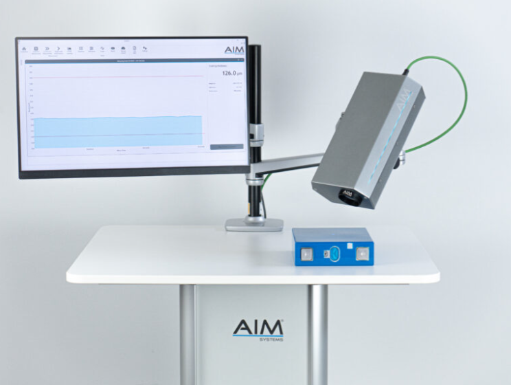
Gauge Advisor sells AIM CoatPro and CoatPro XD systems through the authorized manufacturer sales channel and can quote the equipment around your inspection needs. Request AIM equipment pricing with your coating, substrate, inspection goal and facility location so I can confirm coverage and arrange sample evaluation before final selection.
From light to thickness
Read how heat moves through the coating.
The coating and substrate influence the thermal response together. The result comes from analyzing that response and relating it to known coating thicknesses.
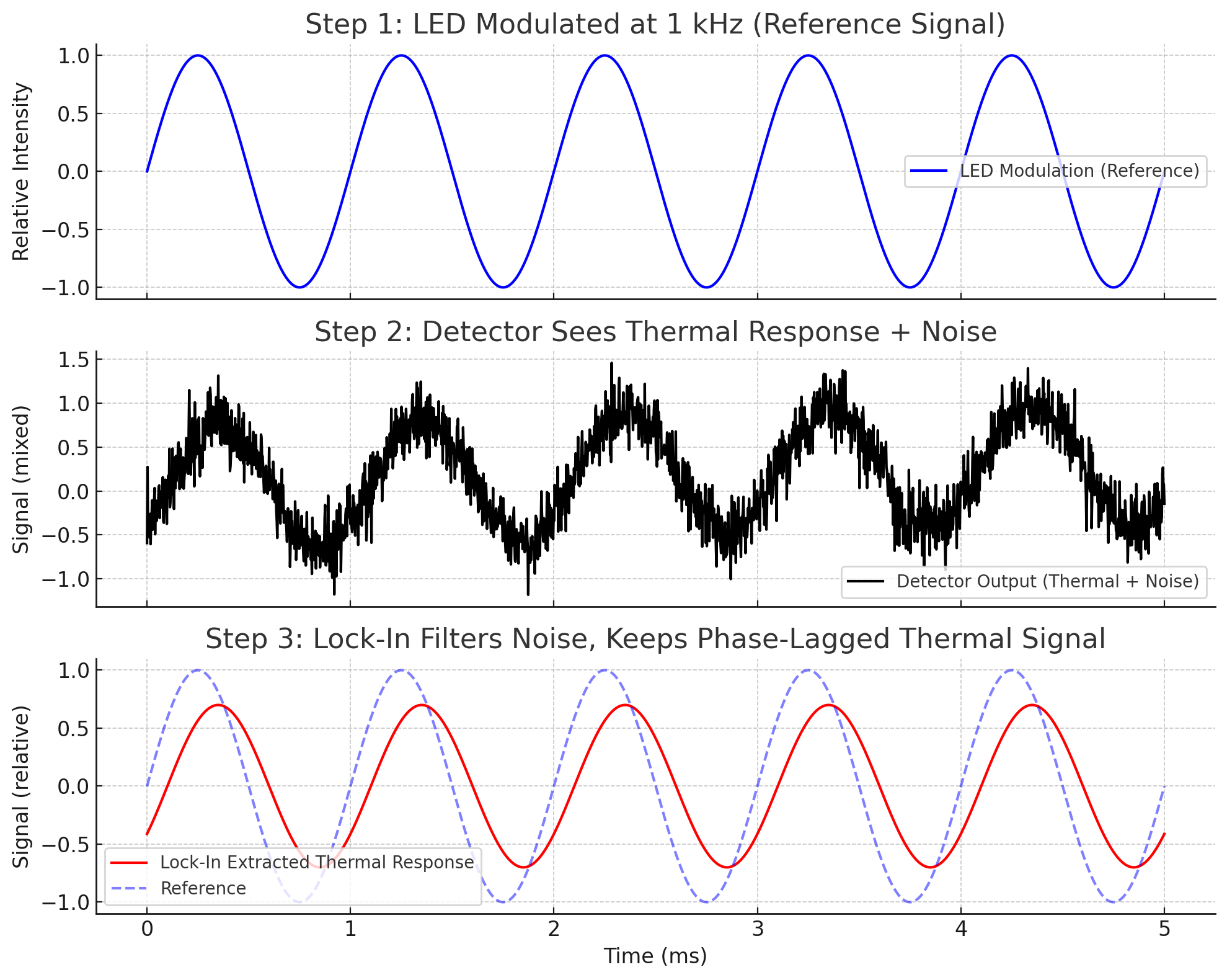
1. Excite the surface
Absorbed light produces a small change in temperature. AIM uses an LED whose output varies periodically.
2. Detect the response
An infrared detector observes the changing thermal signal at the surface. Heat flow depends on the coating, substrate and layer thickness.
3. Apply the calibration
The measured response is compared with reference samples for the material combination and thickness range being inspected.
The detector reads the thermal response. It does not calculate thickness by timing a reflected light pulse. Absorption, heat flow and calibration determine whether the result is useful.
Understanding lock-in detection
Use a known rhythm to find the useful signal.
The LED brightness rises and falls at a known frequency. The coating’s thermal response follows with a delay. Lock-in processing measures that relationship while reducing unrelated signal components.
What does phase mean?
Phase describes where the thermal response sits within each excitation cycle. For a given material system, changes in thickness can change that relationship.
What does the filtering accomplish?
It helps separate the frequency-linked response from background variation. The coating, temperature, motion and optical access still matter to the measurement.
Two excitation approaches
Pulsed and lock-in methods analyze different responses.
Both use photothermal physics. Compare the result on your material, at the required precision and cycle time, when selecting an instrument.
| Method | Excitation and analysis | What to evaluate |
|---|---|---|
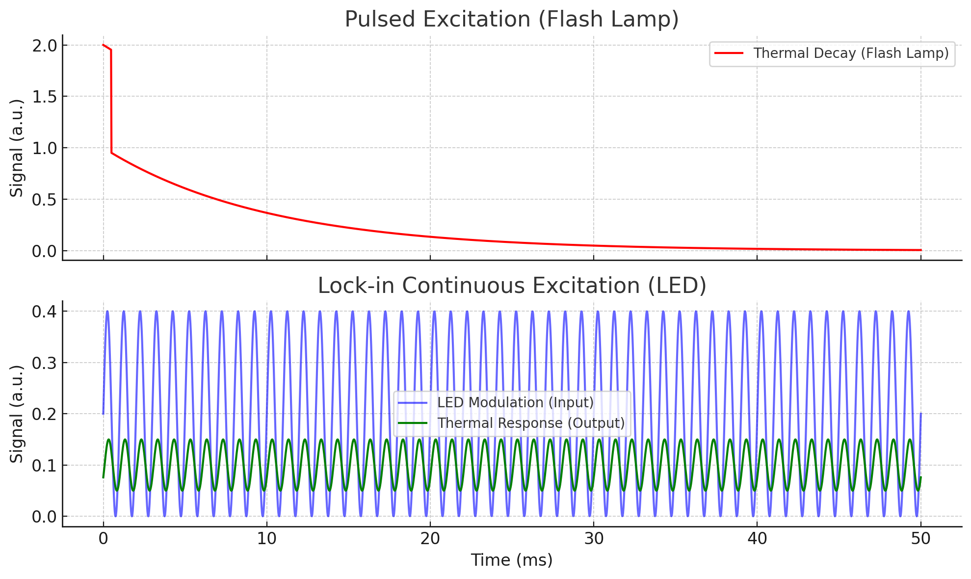
| Pulsed photothermal | A short optical pulse heats the surface. The instrument analyzes the subsequent thermal response over time. | Reference agreement, repeatability and total measurement time on the intended coating. |
| Periodic / lock-in photothermal | Repeatedly modulated light produces a periodic thermal response. Analysis uses its relationship to the excitation. | Reference agreement, frequency and acquisition settings, repeatability and production response time. |
Swipe to see all columns.
View the excitation comparison
What determines the result
A reliable reading starts with the material and the reference.
The same nominal coating thickness can produce a different thermal response on another substrate or in another process state.
| Application factor | Why it matters | What to provide |
|---|---|---|
| Coating and substrate | Light absorption and the thermal contrast between materials affect the response. | Coating chemistry, substrate, color, finish and layer stack. |
| Thickness and tolerance | Sensitivity and useful settings depend on the range. | Low, nominal and high thicknesses, with the tolerance you must resolve. |
| Reference samples | Calibration quality depends on independently established thickness values. | Representative samples across the intended range and the accepted reference method. |
| Time and geometry | Acquisition time affects repeatability; presentation affects optical access and coverage. | Required cycle time, distance, angle, curvature and product motion. |
Swipe to see all columns.
Clear coatings can still be candidates.
Transparency does not automatically exclude a coating. Wavelength, absorption and the complete material stack matter. Clear coats, reflective finishes and thin metallic layers need evaluation using representative samples.
Calibrate the state you intend to measure.
A wet, uncured and fully cured coating can have different thermal properties. If an early reading must predict final dry-film thickness, establish that relationship with matched before-and-after measurements.
Explore coating thickness measurement before cure →Where the method can help
Start with the coating and the inspection question.
Repeat defined measurements on steel or aluminum before or after bake.
Evaluate critical points, a programmed route or local thickness distribution.
Review industrial coatings on metal, plastic and elastomer substrates.
Collect the same sequence of accessible locations on each part or assembly.
Material examples are starting points for testing. The formulation, substrate, thickness and inspection state determine the final fit.
Choose the required coverage
Choose how and where to measure coating thickness.
CoatPro: values at selected locations
Measure at a fixed position, follow a continuous trend at one location, or collect a programmed sequence with controlled motion.
CoatPro XD: a thickness image
Map thickness within a camera’s tested field of view. Additional views or camera modules can extend coverage when the part requires them.
Compare AIM point, sequence and area systems →
Measuring a moving web? A fixed CoatPro can follow one tested lane. For a complete side-to-side profile or coating basis weight, explore web coating measurement systems.
Common questions
Photothermal measurement FAQ.
Is the measurement non-contact?
Yes. Excitation and detection use light, so the sensor does not touch the coating. The energy, measurement settings and presentation are selected for the material.
Is lock-in always better for thin coatings?
There is no universal ranking. Thin-layer performance depends on the material pair, measurement settings, reference samples and available acquisition time. Compare results at your required thickness and tolerance.
Can it measure each layer in a multilayer coating?
Do not assume a single thickness result resolves every layer. Provide the full stack and identify whether you need a combined thickness or separate layer values so the measurement can be evaluated.
How fast is a measurement?
Acquisition time depends on the coating and required repeatability. A production cycle also includes presentation, motion, settling and data handling. Those times belong in the application review.
Can it be used in a hazardous area?
The equipment version and installation must match the environment. AIM offers an ATEX version of CoatPro; confirm the required configuration and local installation requirements during system selection.
Technical resources: AIM photothermal fundamentals · AIM application examples · CoatPro · CoatPro XD.
Application review
Find out whether your coating is a good fit.
Send the material construction and the result you need. I’ll help define a sample study with AIM and the practical route to a lab or production system.
Helpful details to send
- Coating, substrate, finish and any additional layers
- Expected thickness, tolerance and wet or cured state
- Reference samples spanning the range
- Part geometry, accessible area and available measurement time
- The required output: a point, trend, sequence or thickness map
A drawing, part photo or sample description is a useful starting point.