
Biax Film Thickness Measurement & Stretch Profile Control
Measure film before and after stretching to understand how its thickness changes through the line. Scantech combines cross-web low-energy X-ray measurement with stretch-profile analysis, automatic mapping and optional BC3 die control. One- or two-scanner configurations are available for BOPP, BOPET, BOPE, BOPA and other biaxially oriented films.
Choose the configuration for your line: The scanner count, measurement output and control strategy depend on the film structure, stretching sequence, web width and path, edge requirements, and the adjustments the die hardware can make.

The production problem is often locating where variation entered the process
A biaxial line stretches film along its length, called machine-direction orientation (MDO), and across its width, called transverse-direction orientation (TDO). A final profile can show the result without proving whether the variation began at casting, developed through orientation or came from unstable edge behavior.
Cast-sheet variation is hidden later
The final film is wider and thinner, so an upstream die pattern no longer aligns one-to-one with downstream positions.
Stretch response changes the profile
Stretching along and across the line can amplify, redistribute or introduce variation that a final-film scanner sees only after stretching.
Tenter-grip shape affects stability
The edge must remain thick and correctly shaped enough for the clips to grip without turning the trim region into an unmonitored blind spot.
Die corrections need a reliable map
Automatic control must account for measurement positions, material travel time, stretch ratios, the edges included in the calculation, and how each die adjustment affects the film.
Two scanners connect the incoming cast-sheet profile with the final film
Scantech strongly recommends two scanners on many biax lines: one at the cast section and one at the film section. Relating the two profiles improves die mapping, control stability and insight into how the orientation process is performing.
Extrusion die
The cast sheet begins with the current die-lip and actuator profile.
Cast scanner
Scanner one measures the incoming pre-stretch sheet profile.
MDO stage
Machine-direction stretching changes thickness and material coordinates.
TDO and tenter
Transverse stretching expands the web and forms the final edge geometry.
Film scanner
Scanner two measures the post-stretch final-film and edge profiles.
Map, diagnose or optionally regulate
Stretch-aware logic supports diagnosis, operator guidance or qualified upstream control.
Mass conservation and stretch-profile logic make the profiles comparable
The relationship is not simple point-to-point matching. The project must account for scanner registration, machine- and transverse-direction stretch, width change, trim and clip-zone exclusions, line delay and the accepted measurement model before a final-film deviation is assigned to an upstream die zone.
Low-energy X-ray preserves the edge detail the tenter process depends on
Scantech links its X-ray measurement footprint and sensor speed to high-fidelity edge measurement. This is especially relevant where tenter clips require a thicker, correctly shaped region of film or sheet for reliable clamping.
Measure the grip-band shape instead of treating every edge point as trim
On BOPET and other demanding biax processes, the edge profile can influence clip engagement, clip-outs, film breaks and usable width. A well-resolved edge signal gives operators and control logic a clearer view of the transition between the product profile, tenter-grip region and excluded trim.
Confirm edge performance on your line: Edge performance depends on the complete measurement system: the area sensed, sensor response, scanner position, sampling and edge-processing settings. Confirm the required edge detail with the proposed configuration and film.
Total basis weight or calibrated thickness
Define whether production accepts an X-ray mass response, a calibrated thickness result or another qualified output.
Density, fillers, cavitation, layers and formulation changes still belong in the calibration review.Grip band, edge bead, trim and usable web
Agree which edge regions are measured, trended, controlled, alarmed or excluded.
One universal edge cutoff can hide the condition the line is trying to manage.Footprint, sampling and scanner speed
Effective resolution depends on the full measurement and motion system, not sample spacing alone.
Review line speed, scan time, web flutter and the smallest profile feature that must remain visible.Match the displayed result to the accepted result
Use Scantech low-energy X-ray where total-film profile, edge fidelity and non-isotope operation match the production objective.
If a specific layer or constituent is the true target, define that requirement before selecting the measurement model.Need the physics-level comparison? Review X-Ray Transmission Web Gauging for measurement boundaries before treating any sensor label as the complete specification.
ULO3, HF3 and SHF3 cover compact through super-wide biax lines
The published ranges overlap. Width screens the portfolio, but final selection also depends on passline, foundation, opening, service access, environment, sensor count and the mechanical demands at each measurement station.

ULO3
Ultra-light O-frame starting point for cast or film sections where a compact full-pass-through frame fits the line.
- Published product width
- 500 to 3,500 mm
- Selection review
- Opening, passline and access
HF3
Heavy-frame design for wider biax stations requiring greater span, stiffness and structural capacity.
- Published product width
- 500 to 11,500 mm
- Selection review
- Span, stiffness and foundation
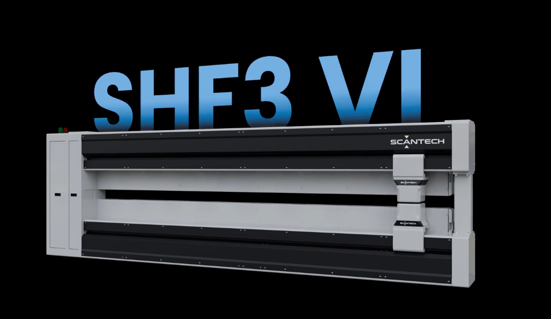
SHF3
Super-heavy frame for very wide measurement stations. The image shows the SHF3 platform with optional integrated visual inspection; dimensional gauging does not require the VI package.
- Standard published range
- 500 to 13,500 mm
- Extended configurations
- Application review up to 15 m
The two stations do not need identical frames. A narrower cast section may fit ULO3 or HF3 while the expanded final film requires HF3 or SHF3. Select each station independently around its measured width, passline, opening, access and structural requirements.

Stretch-aware mapping gives BC3 a more reliable correction target
FlexScan/APC can relate the measured profiles to the upstream automatic die, apply the qualified control model and coordinate corrections through Scantech Bolt Controller 3 or another approved actuator interface. Scantech publishes TDO stretch profile, mass conservation, melt-flow modeling and cascade control as biax capabilities; the model and control-loop design are engineered for each application.
Die coordination: Gauge Advisor has worked with projects involving Cloeren, MAAG, Nordson EDI, maku, JCTIMES and other equipment suppliers. Final compatibility is confirmed from the exact die, actuators, electrical design, controls and drawings.
FlexScan displays the measurements. TREX retrieves production reports.
Operators need the cast profile, final-film profile, stretch behavior, edge rules and control status to remain distinguishable. Production and quality teams then need a configured history that can be retrieved after the roll is complete.
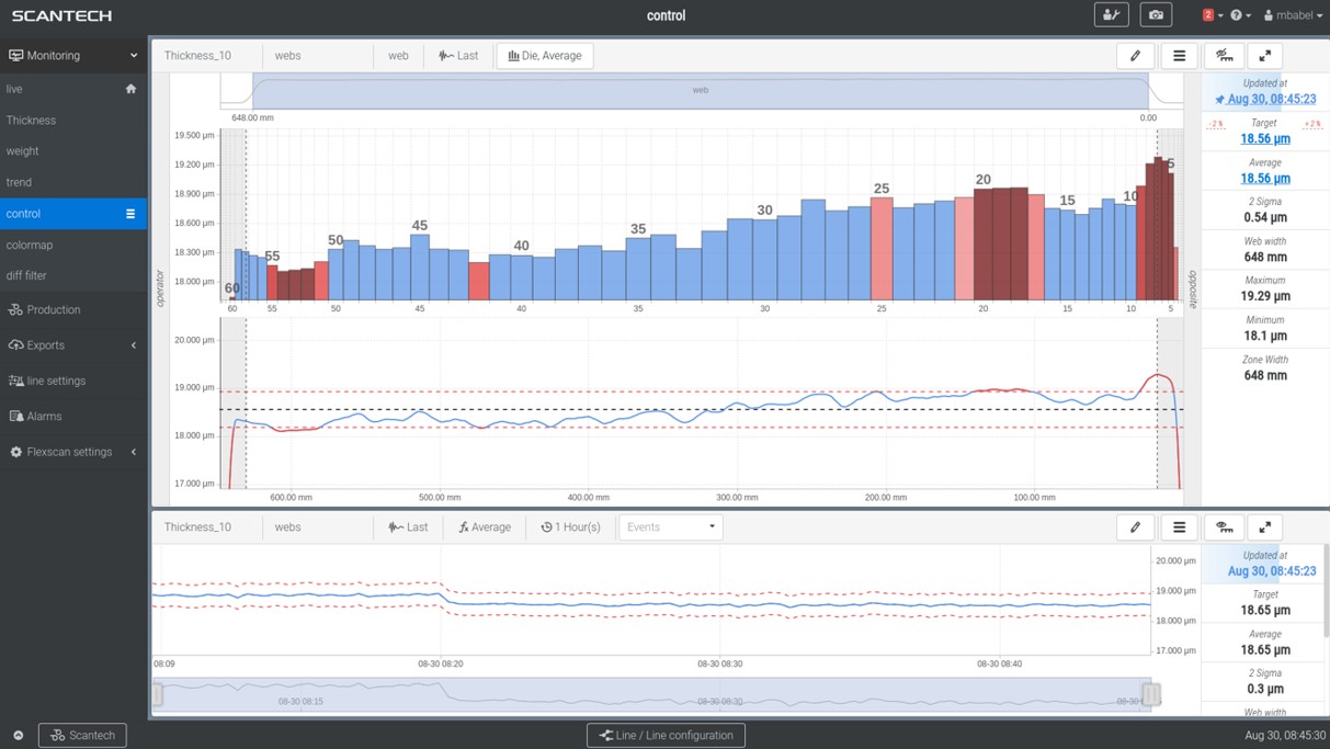
Show measurement, position mapping and correction separately
Configure the operator view around profiles, targets, edge exclusions, mapped zones, trends, alarms, control mode and the response following each qualified correction.

Retrieve completed production reports by meaningful tags
When TREX is included, it can retrieve, sort, categorize and collate archived production reports using configured tags. Report contents, identifiers, retention, user access and plant-interface requirements are defined in the project scope.
Plant connectivity: Scantech publishes OPC UA as standard for the biax system design. Final tag ownership, PLC logic, cybersecurity, retention, remote access and higher-level interfaces remain project-specific.
Review the full line from cast sheet to finished film
Review the line drawing, stretching sequence, required measurement, edge criteria, die adjustment range and reporting needs together when planning two scanner stations.
Film structure and accepted result
Define what the system must measure and what production releases.
- BOPP, BOPET, BOPE, BOPA or other film
- Layers, resin, fillers, cavitation and density
- Nominal range and reference method
MDO and TDO process
Describe how material coordinates change through the line.
- Stretch sequence and nominal ratios
- Widths before and after each stage
- Speed, delay, trim and grade changes
Cast and film scanner locations
Confirm each web can be measured safely and repeatably.
- Passline, opening and measured width
- Flutter, temperature and environment
- Foundation, access and service clearance
Tenter grip and usable-width rules
Separate the regions instead of applying one generic edge cutoff.
- Clip band and edge-bead geometry
- Trim location and usable product width
- Alarm, trend, map and exclusion rules
Die hardware and adjustment range
Document what hardware can make the correction.
- Die supplier, model and drawing
- Bolt count, spacing and actuator type
- Existing PLC, controller and interlocks
Software and acceptance plan
Agree how operators and quality teams will use the result.
- FlexScan views, modes and alarms
- TREX tags, reports and retention
- FAT, SAT, tuning and training
Turn the final-film profile into faster diagnosis and more confident control
Scantech reports that two-scanner biax systems can support more reliable mapping, faster and more stable control and better process insight. Actual results depend on the starting line, film recipe, measurement model, die condition and commissioning.
More reliable die mapping
Relate the expanded final-film profile to the correct upstream material and control zones.
Reach the film specification sooner
Use qualified mapping and cascade feedback instead of repeated manual interpretation.
Better tenter-edge visibility
Monitor the grip-band shape and edge behavior associated with clip stability and usable width.
Clearer production records
Connect live profiles and control behavior with configured TREX history and roll reporting.
Basis weight and physical thickness are not always interchangeableDensity, filler, foam, cavitation and layer changes can change the relationship. Specify the accepted measurement result.
Edge data needs a declared purposeGrip band, edge bead, trim and saleable width may need different trend, alarm, mapping and exclusion rules.
Automatic correction needs compatible die hardwareAutomatic correction still requires a compatible die, sufficient response, safe modes and commissioned control limits.
Connect the biax application to the right supporting resource
Use Web Gauging Systems to compare the complete Scantech system, Automatic Thickness Profile Control for die-control details, and Film & Sheet Measurement to review other process needs.
Web Gauging Systems
Review scanners, measurement technologies, FlexScan, TREX, plant integration and optional control as one production system.
Explore web gauging → Automatic die-control pageThickness Profile Control
Go deeper into mapping, process delay, BC3, die compatibility, retrofit inputs and control acceptance.
Explore automatic control → Extrusion process overviewFilm & Sheet Measurement
Connect biax measurement with cast film, sheet, blown film, web handling and the wider Gauge Advisor offering.
Explore film and sheet solutions →Common biax measurement questions
Why use scanners before and after stretching on a biax film line?
Does every BOPP or BOPET line require two scanners?
Why is low-energy X-ray valuable at the tenter edges?
Does X-ray measure basis weight or true physical thickness?
How do ULO3, HF3 and SHF3 differ?
Can the system automatically correct the final-film profile?
What products can Scantech measure on biax lines?
Where do FlexScan and TREX fit?
Is visual defect inspection included with SHF3?
Can Scantech biax gauging be retrofitted to an existing line?
Start with the line drawing, stretch sequence and the profile you need to explain
Share the line drawing, film construction, stretching sequence and current thickness profiles. Gauge Advisor will help define the measurement, control and reporting requirements and coordinate Scantech’s technical review and quotation.
Equipment project inquiries welcome worldwide. Gauge Advisor reviews your application and coordinates the next step with Scantech.
- Line drawing and stretch sequence
- Cast and final measured widths
- Current profiles and edge examples
- Die, actuators and existing controls
- FlexScan, TREX and acceptance needs