Updated August 3, 2026
A web guide does one job: it keeps a moving web in the correct lateral position. A web guiding system, often called a web guide system or edge guide system, detects lateral web movement and corrects the material before it reaches a critical process. That sounds simple until a label liner changes width, a clear film edge becomes difficult to detect, a coated foil starts wandering after the dryer, or a guide actuator spends the whole run parked near one end of its stroke. The equipment may need to steer the running web, shift an unwind or rewind stand, follow one edge, hold the web center, or track a printed reference. The correct answer depends on where the error begins and what the downstream process must stay aligned to.
Who is FMS? FMS Force Measuring Systems AG is a Swiss manufacturer focused on web tension measurement, tension control, and web guiding for continuous-material processes such as film, foil, paper, labels, coatings, composites, textiles, metal, and wire and cable. Its web-guiding systems combine a steering frame or unwind/rewind actuator with a material sensor and digital controller; Gauge Advisor is the authorized FMS sales and applications support partner for customers evaluating, selecting, and purchasing these systems.
Web wander is a symptom, not a diagnosis
Select the condition that is closest to the problem. The first checks intentionally come before the equipment recommendation.
The web slowly walks sideways
A controlled steering frame can correct normal incoming lateral variation, but first determine whether the drift begins at the unwind, a misaligned roll, a nip, a dryer, a splice, or a downstream section.
Watch the edge before and after each roll. Check roll alignment, bearing condition, web tension, sensor cleanliness, guide direction, and whether the actuator is centered.
Use webMASTER when the running web needs correction, or winderGLIDE when the unwind or rewind stand itself should move laterally.
If the guide stays near one travel limit, repair the continuous alignment or tension bias instead of asking the guide to hold permanent offset.
On extrusion and converting lines, web wandering often traces back to geometry, tension, thickness profile, or an upstream process disturbance. A guide can improve lateral position, but it cannot make unequal web lengths across the width disappear. Gauge bands, baggy lanes, roll misalignment, and unstable bubble motion can continue to steer the material even when the controller is working correctly.[12]
How a web guiding system works
Every automatic web guide follows the same basic loop: detect the reference, compare it with the target, move the guide, and measure again. Use the buttons to see the difference among edge, centerline, and printed-line guiding.
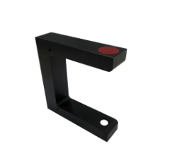
The orange U-shaped sensor remains fixed while the web moves laterally through its sensing window.
One-edge guiding holds a selected edge position
Use one-edge guiding when a die-cut, coating head, slitter, print station, or downstream process references a fixed left or right edge. One compatible sensor is normally used for each guiding loop.
Should you steer the running web, move a roll stand, or use another guide geometry?
The phrase “web guide” covers several different mechanical architectures. The correct one depends on where lateral correction can be introduced without disturbing the process.
Observe the web before and after the unwind, coating section, dryer, laminator, slitter, scanner, and winder.
One edge, the web center, a printed line, or the position of one web relative to another.
Steering frame, steering roller, unwind stand, rewind stand, or a coordinated master-slave loop.
Confirm correction range, speed, thrust, entry and exit spans, and normal incoming wander.
Set control direction, dead band, alarms, PLC communication, safe limits, and operator response.
| Where correction should occur | Best starting architecture | Why it fits | Application boundary |
|---|---|---|---|
Within the running web path Steering frame | FMS-webMASTER BKS015 or BKS030 | The moving upper frame changes roller angle and guides the web in a compact closed loop. | Confirm web width, tension, speed, incoming offset, entry and exit spans, threading, roller surface, and orientation. |
Long free span or special wrap Steering roller | FMS-webDIRECTOR BKS041 or BKS042 | BKS041 is intended for 90-degree wrapping; BKS042 is intended for S-wrapping and long free-span arrangements. | This is not selected by width alone. The web path and available spans determine whether the geometry can steer effectively. |
Unwind or rewind stand Stand positioning | FMS-winderGLIDE D3, D4, or D7 | The actuator shifts the entire stand laterally when adding a steering frame inside the web path is impractical. | Actuator thrust and stroke depend on moving mass, friction, acceleration, mounting geometry, duty cycle, and required correction. |
Two webs entering lamination Chase and follow | BKS309.MS master-slave control | The controller measures the master web and guides the second web so the two material positions match before lamination. | The system requires the correct sensor arrangement and at least one steering device. It cannot correct stretch, curl, or width mismatch between the webs. |
FMS currently groups the web-guiding line into webMASTER steering frames, webDIRECTOR steering rollers, and winderGLIDE actuators. Together, these families cover the primary correction architectures for steering the running web, handling long-span or special-wrap geometries, and positioning unwind or rewind stands.[1]
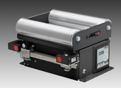
webMASTER covers standard narrow- and medium-width steering-frame applications
FMS currently presents two standard webMASTER steering-frame families: BKS015 for narrow webs and BKS030 for medium-width webs. Applications outside the published ranges move into a custom application review rather than an assumed model recommendation.
FMS-webMASTER
Backlash-free spindle positioning, balanced rollers, edge, center, or line guiding, and a compact frame that becomes part of the web path.
- BKS015 for published roller lengths from 100 to 350 mm
- BKS030 for published roller lengths from 600 to 1,800 mm
- Custom review for the gap between standard families or outside their published limits
BKS309 controller family
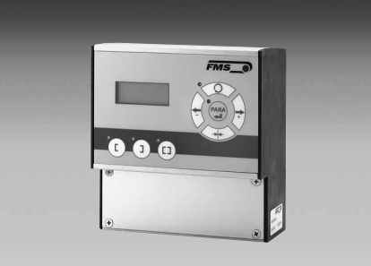
Controls FMS steering frames, steering rollers, and stand actuators. The standard controller supports browser-based Ethernet configuration; BKS309.EIP adds EtherNet/IP.
- Millisecond-class processor cycle
- Edge-left, edge-right, center, and line modes
- DIN-rail, panel, or wall-mount options, depending on version
FMS-winderGLIDE
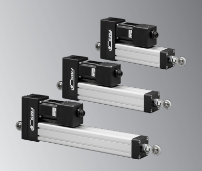
D3, D4, and D7 actuators move a winding stand laterally when the roll position should be corrected instead of inserting a steering frame in the web path.
- Published maximum thrust classes of 650, 1,250, and 4,000 N
- Published stroke options from 125 to 300 mm, depending on model
- Final sizing requires moving mass, friction, acceleration, mounting, and duty cycle
| FMS family | Published application envelope | Drive and correction | Controller and practical fit |
|---|---|---|---|
webMASTER BKS015 Narrow web | Roller length 100 to 350 mm; maximum published speed 400 m/min; maximum published web tension 250 N. | Stepper motor with backlash-free recirculating ball screw; up to 18 mm/s adjustment speed; listed standard configurations provide ±7.5 mm displacement. | Integrated BKS015 electronics are the normal compact path. Strong for labels, narrow laminates, adhesive webs, isolation layers, and compact retrofits. |
webMASTER BKS030 Medium-width web | Roller length 600 to 1,800 mm; maximum published speed 600 m/min; maximum published web tension 750 N. | Stepper motor with backlash-free recirculating ball screw; up to 35 mm/s adjustment speed; listed standard configurations provide ±22.5 to ±60 mm displacement. | Uses BKS309 control electronics. Strong for film conversion, extrusion, coating, slitting, rewinding, and packaging lines within the published envelope. |
webDIRECTOR BKS041 / BKS042 Long free span | Roller length 600 to 1,600 mm; maximum published speed 600 m/min; maximum published web tension 500 N. | BKS041 for 90-degree wrap; BKS042 for S-wrap; up to 25 mm/s adjustment speed and a published maximum web-offset value of 120 mm. Confirm usable recovery for the actual geometry. | Use when the web path and free spans favor a steering-roller architecture rather than a compact pivoting frame. |
Custom FMS configuration Application review | Widths, speeds, tensions, environments, surfaces, or geometry outside the standard tables. | Special roller material, coating, frame construction, mounting, or coordinated control can be reviewed. | Do not bridge the 350 to 600 mm standard-family gap by guessing. Send the actual web and machine data to Gauge Advisor for application review and final confirmation with FMS. |
Choose the sensor from what must be detected, not from the web width alone
The guide can only be as reliable as its position reference. A clear film, an opaque paper edge, and an intermittent printed line require different sensing approaches.

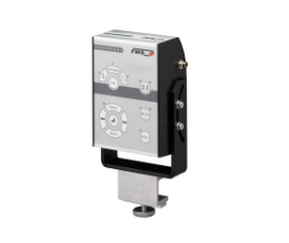
| What the guide should follow | Strong FMS starting point | Why | What still must be confirmed |
|---|---|---|---|
One edge of clear or transparent film | US01B or US04B ultrasonic edge sensor | Ultrasonic sensing is not dependent on visible color contrast and is well suited to transparent and reflective webs. | Required sensing range, edge movement, material planarity, mounting, dust, web flutter, and sensor access. |
One edge of opaque paper, foil, or colored film | AZS01B or AZS04B optical edge sensor | Optical BlueFlash sensing provides high-resolution edge mapping for opaque material. | Edge contrast, ambient light, edge condition, sensing range, mounting, and whether coating or adhesive contamination can reach the optics. |
Both edges or the web center | Two compatible edge sensors | The controller calculates the center from the two edge positions, allowing width variation while the center remains aligned. | Sensor spacing, expected minimum and maximum width, whether width variation is real product change or an unstable process, and adjustment access. |
Printed line or registration feature | DLS2 optical line sensor | The sensor follows the line rather than the physical web edge, which is useful when coating, print, or die-cut registration is the actual requirement. | Line color, background, width, solid or intermittent pattern, crossovers, print quality, contamination, and required resolution. |
Complex printed feature without a dedicated guide line | Application review | The standard FMS sensing paths are based on a web edge, the calculated web center, or a printed line that the DLS2 can follow. | Whether the process can provide a stable printed guide line and whether DLS2 can detect that reference reliably on representative material. |
Where webMASTER fits on labels, adhesive coating, battery, film, and composite lines
Web guiding is not selected in isolation. The correct location and reference depend on the process step that must remain aligned. Select an application to see the likely problem, the first checks, and the equipment path.
Pressure-sensitive labels: hold print, liner, and die-cut registration
A pressure-sensitive label construction may combine facestock, adhesive, and release liner, then pass through printing, coating, laminating, die cutting, matrix stripping, inspection, slitting, and rewinding. The guide reference should follow the feature that protects the next critical operation, not automatically the nearest web edge.
- Use BKS015 as the compact starting family when the narrow-web width, speed, and tension fit its published range.
- Use one-edge guiding when the process references a fixed edge; use center guiding when changing liner or facestock width must remain centered.
- Use printed-line guiding when artwork or registration, rather than the raw edge, controls the die-cut or inspection position.
Separate web wander from die wear, plate or sleeve registration, stretch, liner curl, adhesive contamination, and matrix-strip tension.
BKS015, the suitable edge or line sensor, and integrated or external control depending on the application.
Thinner liners, higher speeds, material savings, and shorter runs reduce operating margin and make stable web position more valuable.
1. Pressure-sensitive label coaters and converters
Label lines are a strong fit for compact closed-loop guiding because the material is often narrow and every downstream feature is position-sensitive. In 2026, industry coverage continues to emphasize higher converting speeds, wider webs, thinner liners, automation, and material reduction. Those trends increase the value of precise lateral positioning because a smaller trim allowance or thinner liner leaves less room for hunting and registration loss.[10]
For a junior engineer, the key question is: What must stay aligned? If the answer is the physical liner edge, use edge guiding. If the answer is the center of changing web widths, use two sensors and center guiding. If the answer is a printed registration feature, guide from the line. A sensor that follows the wrong reference can hold the web very accurately in the wrong place.
2. Adhesive coating, protective film, and laminating
Soft films and adhesive-coated webs can wrinkle from the same tension used to present them to the coating head. A Pressure Sensitive Tape Council technical paper on protective-film coating describes wrinkle formation around a Mayer-bar process and the importance of controlled web tension and wrap.[9] This is why guiding and tension should be diagnosed together.
Use webMASTER to keep the substrate or liner at the required lateral position through coating, drying, laminating, or slitting.
Use FMS force sensors when drive current, brake pressure, or dancer position does not provide enough confidence in the real web force.
Use BKS309.MS chase-and-follow control when a master web and a second web must enter lamination in the same lateral position.
A coating gauge answers a different question. Scantech can measure basis weight, coat weight, thickness, or profile across the web, while FMS guiding keeps the substrate in the correct lateral path. A perfect coating profile does not prove the liner is registered, and a perfectly guided web does not prove the adhesive coat weight is correct. For the measurement side of the project, see the web coating measurement guide and the coating measurement systems overview.
3. Battery electrode coating and slitting
Battery electrode manufacturing is a roll-to-roll process built around thin metal foil, coating, drying, calendering, slitting, and winding. DOE programs have repeatedly emphasized coating uniformity, inline inspection, and scrap reduction because defects can otherwise move downstream into higher-value material and finished cells.[11] For the separate basis-weight and thickness decision, see the battery coating x-ray versus beta guide.
Keeps copper or aluminum foil, coated lanes, and slit material aligned through the process.
Measures actual web force and can reveal tension changes through coating, drying, calendering, and winding.
Shows whether zones or individual slit lanes carry different tension even when the average appears acceptable.
Measures coating basis weight, thickness, profile, and related signals according to the selected scanner architecture.
4. Blown film, cast film, and sheet conversion
On a blown-film line, lateral movement can originate upstream at the bubble, collapsing frame, oscillating haul-off, or layflat. Addex equipment addresses cooling, bubble stability, and thickness-profile control upstream. Scantech verifies thickness or basis-weight profile. FMS guiding becomes most relevant after the web has become a stable layflat or flat web and must pass accurately through scanning, treatment, slitting, bag making, laminating, or winding. The blown film gauge-variation guide and blown film bottlenecks guide help separate those upstream causes from a true downstream guiding problem.
5. Prepreg, coated fabrics, and composite webs
Prepreg lines may need reinforcement, resin film, release paper, liner, coating lanes, and slit positions to remain aligned while heat, pressure, tack, and cooling change how the material behaves. Scantech can measure basis weight or profile, while FMS controls tension and lateral position. The web guide should be placed where it protects the next process without marking a tacky or sensitive surface. The prepreg manufacturing guide connects those measurement, tension, guiding, slitting, and winding decisions across the full line.
6. Slitting and rewinding
At a slitter, lateral position controls trim, lane location, knife alignment, core alignment, and roll face. But a good edge position does not prove equal lane tension. Use conventional FMS load cells for total tension and segFORCE when individual lanes or cross-web zones must be compared. The segmented tension roller guide explains when one average hides lane-to-lane differences. A telescoped roll can result from poor guiding, poor winding tension, thickness bands, shaft or chuck problems, entrained air, or an unstable incoming parent roll. Inspect the first point where the defect appears.
Build an FMS web-guiding path in about 60 seconds
This tool identifies a practical starting architecture and the information that still needs factory review. It does not replace a web-path drawing, representative material, or final FMS sizing.
What is narrower edge trim worth?
Better lateral control may allow a validated process to reduce trim allowance, but the guide alone does not establish the new limit. Use this calculator to quantify the material value after process capability, slitter alignment, coating edges, web width, and quality requirements have been proven.
Calculation boundary: recovered width equals two times the difference between current and target trim per side. Area equals recovered width times annual length. Mass equals area times total basis weight. The model excludes equipment cost, yield changes, downtime, start-up scrap, coating edge quality, slitter limits, product mix, and qualification. Do not count the same material in another ROI category.
Web guiding, tension control, and coating profile solve different problems
A line can have a stable edge and bad tension, or a stable tension average and bad coating profile. The strongest diagnosis keeps each measurement tied to one physical question.
Where is the web edge, center, or printed line relative to the setpoint? The output drives a steering frame, steering roller, or stand actuator.
How much tension is the moving web carrying at a defined roller and process zone? This can support monitoring or closed-loop tension control.
Are individual zones or slit lanes tighter or looser than the average? This helps isolate baggy lanes and local winding differences.
Is the film, coating, foil, laminate, or sheet heavy, light, thick, or thin across the width and through the roll?
Check roll alignment, sensor reference, guide geometry, incoming roll position, actuator centering, and the first point where lateral movement begins.
Investigate thickness bands, baggy lanes, roll alignment, cross-web tension, nip geometry, entrained air, and thermal shrinkage. More guide gain may make the wrinkle worse.
Decide whether the coater should follow the substrate edge, a printed line, or a registered upstream position. A guide can hold the selected reference but cannot correct a coating-head profile error.
Common web-guiding mistakes
Installing the guide where the error is already too late to correct
A guide protects the process downstream of its correction point. Place it close enough to the coating head, print station, scanner, slitter, nip, or winder to control the required position, while preserving the entry and exit spans the guide geometry needs.
Using the web edge when the actual requirement is print or coating registration
The physical edge can move independently of a printed line, coating lane, or die-cut feature. Choose the reference from the downstream quality requirement. DLS2 line guiding is often more appropriate when the feature inside the web is what must stay aligned.
Using center guiding when one edge must remain fixed
Center guiding allows both edges to move as width changes so the web center remains stable. That is useful when centerline matters. It is the wrong mode when one edge is the fixed datum for a slitter, coater, or print station.
Trying to pull wrinkles flat with more tension
Wrinkles can come from unequal web length, thickness bands, roll misalignment, thermal shrinkage, entrained air, or cross-web tension differences. Higher tension may temporarily flatten one symptom while stretching the web or creating another wrinkle.
Increasing controller gain when the actuator is mechanically saturated
If the frame or stand stays near one end of travel, the guide has no remaining authority in that direction. Recenter the mechanics, reduce incoming offset, repair alignment, or increase the approved correction range. More gain cannot create missing stroke.
Selecting a sensor only from total web width
The small and large FMS sensor versions are selected from the required sensing window, expected edge movement, material behavior, and mounting. A 1,500 mm web can still need a small sensor if its edge stays within a narrow range.
Calling a clear or reflective web an optical-edge application without testing it
Transparent film, reflective foil, changing opacity, coating buildup, and ambient light can undermine an optical edge signal. Ultrasonic sensing is the safer starting point for many clear and reflective webs, but the real material should still be tested.
Assuming a downstream guide will correct blown-film bubble movement
When lateral motion follows bubble sway, frost-line movement, collapsing-frame instability, or oscillation, the upstream blown-film process should be corrected first. The downstream guide should handle the remaining stable-web variation.
Expecting edge guidance to prove equal slit-lane tension
A slitter can hold the parent edge accurately while individual lanes carry different tension. Use segFORCE or another appropriate lane-tension method when the failure mode is local winding or cross-web mechanical variation.
Quoting a standard model without checking speed, tension, spans, surface, and environment
Published width is only one screen. Final selection needs minimum and maximum tension, speed, thickness, material, incoming offset, entry and exit span, roller surface, orientation, controller location, sensor, environment, and service access.
Web guiding system application checklist
Collecting these values before quotation prevents a width-only recommendation and makes the factory review much faster.
- Process and correction pointLabel press, adhesive coater, laminator, battery line, film line, slitter, rewinder, prepreg line, or another process; running web, unwind, rewind, or special span.
- Reference to followLeft edge, right edge, web center, printed line, coating boundary, master web, or other feature.
- Material and surfaceClear, translucent, opaque, reflective, printed, tacky, abrasive, porous, foil, paper, liner, film, fabric, or composite.
- Minimum and maximum widthInclude product changes, edge movement, trim, and the actual width at the guide location.
- Minimum and maximum tensionUse measured web force by zone when available, not only brake pressure, drive torque, or dancer position.
- Minimum and maximum speedInclude normal production, threading, ramp, splice, and maximum operating conditions.
- Incoming lateral errorNormal and worst-case edge movement, splice disturbance, roll-to-roll offset, and whether the guide recenters between runs.
- Entry and exit spansProvide the passline drawing, wrap, roller locations, free spans, threading direction, and available correction space.
- Roller and contact requirementsDiameter, face length, aluminum, anodized, cork, special coating, cleanliness, abrasion, tack, temperature, and product-contact restrictions.
- Controller and integrationIntegrated or external controller, DIN rail, panel, wall mount, standard Ethernet, EtherNet/IP, digital I/O, alarms, and cable lengths.
- EnvironmentTemperature, dust, moisture, solvent, washdown, dry room, cleanroom, food, battery contamination, guarding, and service access.
- Representative evidencePhotos, video, edge-position trend, web-path drawing, product samples, tension trend, profile data, current trim, and the first location where the problem appears.
Continue the web-handling and measurement plan
These pages connect the guiding decision to the tension, coating, film, battery, prepreg, and profile questions that often sit around it.
Web guiding and FMS webMASTER FAQs
What is a web guiding system?
A web guiding system measures the lateral position of a moving web and corrects that position through a steering frame, steering roller, unwind actuator, or rewind actuator. It controls edge, centerline, line, or another defined reference. It is different from web tension control, which regulates pulling force.
Why does a web guide hunt or oscillate?
A web guide may hunt when controller gain is too aggressive, the sensor signal is unstable, mechanical play is present, the actuator is near the end of its stroke, or the guide is correcting an incoming disturbance faster than the web path can respond. Check the sensor, guide mechanics, actuator position, tension, roller alignment, and incoming web behavior before increasing controller settings.
What information is needed to size a web guiding system?
Useful starting information includes the web material and transparency, minimum and maximum width, line speed, web tension, incoming lateral error, guide location, available entry and exit spans, threading direction, environment, required correction stroke, actuator load, sensor reference, and PLC communication. A web-path drawing and representative photos or video make the application review much faster.
Can a web guide be retrofitted to an existing coating, label, or slitting line?
Yes, in many cases. A retrofit review should confirm available space, web path, roller spans, material behavior, mounting structure, sensor location, actuator travel, controls, safe threading, and maintenance access. Gauge Advisor can review the existing line, help select the FMS guide, sensor, controller, and actuator, and coordinate the final configuration with FMS.
What is the difference between edge guiding and centerline guiding?
Edge guiding holds one selected web edge at a target position and normally uses one sensor. Centerline guiding uses two edge sensors and holds the calculated center between them. Center guiding is useful when width changes but the process must remain centered. Edge guiding is better when one edge is the fixed datum.
When should I use an ultrasonic web guide sensor?
Ultrasonic sensing is the normal starting point for transparent film, reflective material, and edges with poor optical contrast. It is also relatively insensitive to dust and ambient ultrasonic noise within its intended application. Final selection still requires the actual sensing range, web behavior, and mounting.
When should I use an optical edge sensor?
Use an optical edge sensor when an opaque paper, foil, colored film, fabric, or other material provides a dependable physical edge. Confirm edge contrast, ambient light, contamination, transparency changes, and whether the material stays flat in the sensing window.
Can FMS guide from a printed registration line?
Yes. The DLS2 is designed for line and edge detection, including solid and intermittent lines. The printed feature, background, pattern break, crossover, line width, and print quality should be reviewed on representative material.
Which web references can an FMS guide follow?
Standard FMS guiding supports one-edge control, two-edge centerline control, and printed-line guiding with the DLS2. When the process does not provide one of those stable references, review whether a dedicated printed guide line can be added before the sensor and controller are selected.
What is the difference between webMASTER and winderGLIDE?
webMASTER is a steering frame installed in the running web path. winderGLIDE is an actuator that shifts an unwind or rewind stand laterally. The choice depends on where correction can be introduced and what moving mass, span, and machine space are available.
Which FMS webMASTER model fits my width?
BKS015 has a published roller-length range of 100 to 350 mm. BKS030 has a published range of 600 to 1,800 mm. Widths between those standard ranges, or outside them, require a custom FMS review. Speed, tension, offset, spans, surface, and environment must also fit.
Is motorized sensor adjustment available from FMS?
No. The material sensor is positioned and fine-adjusted manually for the selected edge or printed-line reference. The automatic guiding motion is still motorized: the steering-frame drive or winderGLIDE actuator moves the web path or roll stand in response to the controller.
Can a web guide fix wrinkles?
Only when the wrinkle is primarily caused by lateral misalignment that the guide can correct. Wrinkles can also result from unequal web length, thickness bands, tension imbalance, roll alignment, thermal shrinkage, entrained air, nip geometry, or poor spreading. Diagnose where the wrinkle first appears before changing guide settings.
How close should the web guide be to the process?
Close enough to control the required downstream position, but with the entry span, exit span, wrap, and threading needed for the guide geometry to work. The sensor is normally placed near the guide exit where it can measure the corrected position. Final placement should follow the approved FMS layout.
Can FMS coordinate two webs before lamination?
Yes. BKS309.MS provides master-slave chase-and-follow control for laminating two webs. It uses an additional material sensor to measure the master web and guides the second web to match its lateral position. It does not correct material stretch, curl, width mismatch, or coating profile.
References and further reading
These sources support the product details, application guidance, and process context discussed in this article. They remain collapsible for easier reading and open automatically when printing.
Open references and further reading18 sources
Gauge Advisor is the authorized FMS sales and applications support partner and also represents Scantech and Addex for complementary measurement and blown-film process-control applications. FMS sources support the product descriptions and published specifications used in this guide. DOE, PSTC, and industry sources provide roll-to-roll, adhesive-coating, battery, label-market, and process-diagnostic context.
- FMS, Overview Web Guiding Solutions. Current family overview for webMASTER BKS015 and BKS030, webDIRECTOR BKS041 and BKS042, winderGLIDE D3, D4, and D7, sensors, accessories, and published operating envelopes.
- FMS, BKS015 compact steering frame. Current product dimensions, adjustment speed, integrated controller architecture, sensor placement, and narrow-web configurations.
- FMS, BKS030 steering frame. Current medium-width configurations, roller lengths, displacement, adjustment speed, and installation guidance.
- FMS, BKS309.R.EIP web guide controller. EtherNet/IP, processor cycle, mounting, control modes, and integration information.
- FMS, BKS309.R.MS master-slave controller. Chase-and-follow control for laminating two webs and compatible FMS steering devices and sensors.
- FMS, US01B ultrasonic edge sensor. Transparent and reflective material detection, 2 ms cycle, IP67 rating, and sensor-family compatibility.
- FMS, DLS2 digital line and edge sensor. Line and edge modes, 0.06 mm resolution, intermittent-line handling, and current product information.
- FMS Download Center and webMASTER data-acquisition documents. Application data requirements covering tension, speed, width, thickness, material, incoming offset, spans, sensors, control modes, rollers, orientation, and controller configuration.
- Pressure Sensitive Tape Council technical seminar paper. Protective-film adhesive coating, controlled tension, and wrinkle behavior around a Mayer-bar process.
- Labels & Labeling, 2026 Global Predictions. Higher converting speed, wider webs, thinner liners, material savings, and increasing process-stability demands.
- U.S. Department of Energy, Advanced Batteries R&D Progress Report. Battery-electrode coating uniformity, inline monitoring, manufacturing defects, yield, safety, and cost context.
- Gauge Advisor, Plastics Extrusion Troubleshooting Guide. Process-first diagnosis for web wander, wrinkles, baggy lanes, roll build, thickness bands, tension, and upstream instability.
- Gauge Advisor, Coating Thickness Measurement Systems. Separation of coating basis weight, physical thickness, density, scanning profile, and related measurement methods.
- Addex, External Gauge Control. Blown-film cooling and thickness-profile control used to separate upstream bubble and gauge problems from downstream flat-web guiding.
- Gauge Advisor, Web Tension & Guiding Equipment Selector. Preliminary FMS force sensor, control, segFORCE, steering frame, actuator, material sensor, and controller selection workflow.
- FMS, FMS-segFORCE segmented tension roller. Cross-web and slit-lane tension measurement used to distinguish local tension variation from simple lateral position error.
- U.S. Department of Energy, Roll-to-Roll Processing Technology Assessment. High-throughput continuous-web manufacturing context across coatings, batteries, films, printing, and other web processes.
- FMS, Steering Frames for Web Guiding. General steering-frame application overview. Final product options and configuration are confirmed during the FMS application review.
Ready to discuss a web guiding system?
Gauge Advisor is an authorized FMS sales and applications support partner. When you are ready to move from diagnosis to equipment selection, Gauge Advisor is your point of contact for FMS web guiding. I help label, adhesive, coating, battery, film, sheet, prepreg, laminating, slitting, and converting manufacturers evaluate, select, quote, integrate, and support webMASTER, webDIRECTOR, winderGLIDE, BKS309 controllers, material sensors, tension measurement, tension control, and segFORCE systems.
Send the web-path drawing, material, width, speed, tension, incoming offset, entry and exit spans, correction point, sensor reference, environment, and representative photos or video when available. I will review the application, narrow the steering device, sensor, controller, and actuator path, coordinate final confirmation with FMS, prepare the quotation, and support the project through integration. I will respond within one business day, often within a few hours.
- webMASTER BKS015, BKS030, and custom-frame review
- webDIRECTOR long-span and special-wrap review
- winderGLIDE unwind and rewind actuator sizing
- Optical, ultrasonic, centerline, and line-sensor selection
- BKS309, EtherNet/IP, and master-slave lamination control
- FMS tension, segFORCE, Scantech, and Addex coordination