Updated October 9, 2026
Film extrusion is controlled twice before the roll reaches the winder. First, the line must deliver the intended resin, reclaim, color, barrier material, slip, antiblock, and other ingredients to each extruder at the correct mass rate. Second, the line must distribute that melt into the intended thickness profile across the web and over time. Gravimetric blending controls what enters the process. Online thickness gauging shows what the process actually produced. The strongest results come when both systems are connected to the physical variables that can correct the loss.
Which film extrusion upgrade should you evaluate first?
Describe the loss you are trying to reduce and your current equipment. Gauge Advisor can help scope an ABS gravimetric blending project, a Scantech gauging project, or a coordinated review of both.
Review gravimetric blending when ingredient dosing, reclaim handling, or mass-flow consistency is the concern.
Review online gauging when the line needs better measurement of average thickness and cross-web variation.
Separate feed-control needs from measured profile and correction needs, then define the equipment and integration scope.
Start with three details. These are optional; share what you know and we can clarify the rest.
Continue to the contact form to add your contact details and send your request. Gauge Advisor provides authorized ABS and Scantech sales and applications support.
Connected process path: Connect recipe accuracy to actual line output by coordinating continuous blending, throughput control, reclaim, melt delivery, and inline thickness measurement.
Related next steps: continuous gravimetric blenders, throughput-control weigh hoppers, film-scrap repelletizing, film and sheet melt delivery, and film and sheet measurement systems.
A stable film profile does not prove the recipe is right
Blending and thickness gauging answer different questions. The blender measures and controls ingredient mass flow. The web gauge measures the resulting film or sheet profile after extrusion, cooling, stretching, and web handling. A plant needs to keep those two data sets separate before correlating them.
Ingredient ratios, total mass flow, and web profile are behaving as expected. Continue verifying finished-film properties, calibration, recipes, and the laboratory release method.
Total thickness may look acceptable while color, seal, barrier, stiffness, coefficient of friction, or reclaim percentage drifts. Investigate material identity and component flow before changing die or cooling settings.
The recipe may be correct while the die, air ring, cooling, casting roll, hauloff, stretch section, line speed, or winding changes the thickness profile.
Do not tune several loops at once. Establish ingredient and throughput stability first, then separate machine-direction variation from cross-direction profile variation.
Film properties depend on resin composition, additives, layer structure, melt preparation, die distribution, cooling, stretching, and winding. A polyolefin processing guide from LyondellBasell treats material handling, blending, dies, cooling, gauge measurement, controls, and winding as connected parts of the film process rather than isolated purchases.[13]
Where blend control and thickness control fit on the line
Click each stage to see what should be measured, what can be controlled, and what the next stage cannot repair.
1. Material source and routing: prove the correct ingredient reaches the correct extruder
A perfect blender recipe cannot compensate for the wrong resin source, contaminated reclaim, moisture, a bridged hopper, or a connection error. The control architecture begins before the load cells.
- Verify resin identity, source, lot, reclaim stream, drying condition, and available inventory.
- Match vacuum receivers, feeder style, line size, and routing to pellets, powders, flakes, and regrind.
- Use routing verification where several materials and extruders share a central system.
Continuous gravimetric versus batch gravimetric blending
Both architectures weigh ingredients. The important difference is when they weigh, how they meter material to the process, and how quickly the control system sees a change.
Sequential gain-in-weight dosing
- Can be practical for stable recipes, moderate component counts, and applications where a properly sized mixer and surge section buffer the cycle.
- Often familiar to operators and can provide a lower-complexity path for less demanding applications.
- Performance depends on batch size, cycle time, discharge, mixer design, surge capacity, material flow, and the process demand below it.
Each component is weighed and metered continuously
- Provides component-by-component mass-flow data and can adjust feeder output as the process rate or recipe changes.
- Reduces dependence on one repeated batch cycle when short-term ratio control matters.
- Particularly useful for multilayer film, expensive low-rate additives, reclaim control, frequent rate changes, and high-throughput lines.
Academic control work on continuous gravimetric blenders describes a dedicated meter for each polymer or additive, load-cell-based flow estimation, regulation of each stream, preservation of the recipe ratio, and coordination with extruder demand.[6] That architecture provides more direct short-term information than a completed-batch total, but it still needs the correct feeder, stable refills, vibration isolation, material flow, and a validated operating range.
| Decision point | Batch gravimetric | Continuous gravimetric | What to verify |
|---|---|---|---|
How ingredients are controlled | Sequential weights build a common batch before mixing and discharge. | Each ingredient has a measured feed rate and is metered simultaneously. | Ingredient count, minimum and maximum component rates, refill behavior, and actual process demand. |
Short-term recipe visibility | The controller confirms each completed batch, while the process sees the blended output through a surge section. | The controller can trend each component mass flow and recipe ratio as the line runs. | Data update rate, alarm logic, feeder response, residence time, and the delay to the extruder. |
Rate and recipe changes | The new recipe appears through the next completed batches and downstream holdup. | Setpoints can change together, but old material still remains in feeders, piping, hoppers, extruders, and dies. | Complete material path and transition volume. No blender makes a long coextrusion system change instantly. |
Best fit | Stable recipes, lower control complexity, and applications where demonstrated blend uniformity is already adequate. | Film lines needing direct component flow, low-rate additive control, multilayer coordination, reclaim tracking, or frequent output changes. | Finished-film property data, not only blender display values. |
Main implementation risks | Poor discharge, inadequate mixing or surge, segregation after discharge, cycle interaction, and slow changeovers. | Refill disturbance, vibration, wrong feeder type, bridging, low-rate resolution, air pressure, and control tuning. | Representative materials and the lowest, normal, and highest production recipes. |
Where ABS continuous blenders fit in film extrusion
ABS offers two continuous gravimetric platforms, several feeder styles, plant controls, routing verification, conveying, drying, cleanout, and reclaim equipment. The blender should be selected as part of the complete material path rather than as a stand-alone frame.

SIMPLICITY continuous blender
ABS uses simultaneous component metering with maintenance-free vibratory feeders, feeder identification, a recipe manager, and an operator touchscreen. Published S-series starting sizes span estimated rates from 500 to 6,000 lb/h, depending on model, material, and run conditions.[1]
- Virgin, color, additives, powders, and regrind feeder options
- Weigh-hopper, vacuum takeoff, and remote pressure-convey discharge options
- Strong fit for high-rate film and multilayer extrusion
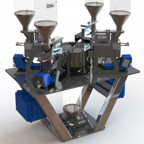
SL, SLX, and SL1
The SL family uses integral weighed downcomers in a compact continuous loss-in-weight architecture. ABS publishes estimated starting rates up to 200, 500, and 1,000 lb/h for the SL, SLX, and SL1 respectively, with optional integrated vacuum sequence manifolds.[2]
- Compact machine-side or mezzanine layout
- Six-component configurations shown by ABS
- Useful for smaller film lines and individual coextrusion layers
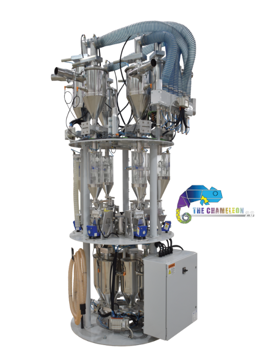
Chameleon 2.0 and controls
Chameleon 2.0 automates component draining and uses vacuum and compressed air for cleanout. ABS states that it can reduce purge waste and increase runtime. It is available only on new blenders and is not a retrofit for existing units.[3]
- Evaluate when frequent resin or color changes dominate labor and transition scrap
- Pair with recipe, routing, and collection strategy
- Do not quote a universal cleanout time without the actual configuration
Free-flowing pellets, low-rate powders, color concentrates, flake, and irregular regrind do not meter the same way. Each component rate must fit a suitable feeder.
ABS SMART is designed for complex coextrusion and centralized plants and verifies that material connections agree with the recipe.[5]
ABS offers scalable Allen-Bradley and Beckhoff architectures, extrusion-throughput control, vacuum sequencing, temperature modules, and supervisory integration.[4]
Feeder access, calibration checks, spare parts, operator training, remote diagnostics, and plant ownership of the control architecture affect long-term performance.[16]
Use the Resin Handling System Selector to screen the blender, feeder, conveying, drying, reclaim, storage, and control requirements together.
Thickness gauges separate machine-direction variation from cross-direction profile
An online scanner does more than display one average. It shows how the film changes across the web and how the average changes over time. That distinction points to different causes and different actuators.
Persistent lanes across the width often point toward die distribution, lip condition, thermal bolts, casting-roll effects, air-ring cooling, bubble mapping, or stretch-profile behavior.
Average gauge moving over time can follow total mass flow, extruder output, line speed, pressure, temperature, cooling, draw, or a control loop that is hunting.
The scanner measures the finished profile at its installed location. It does not by itself identify the root cause. Correlate the profile with blender mass flow, extruder pressure and speed, die or air-ring position, line speed, and roll data.
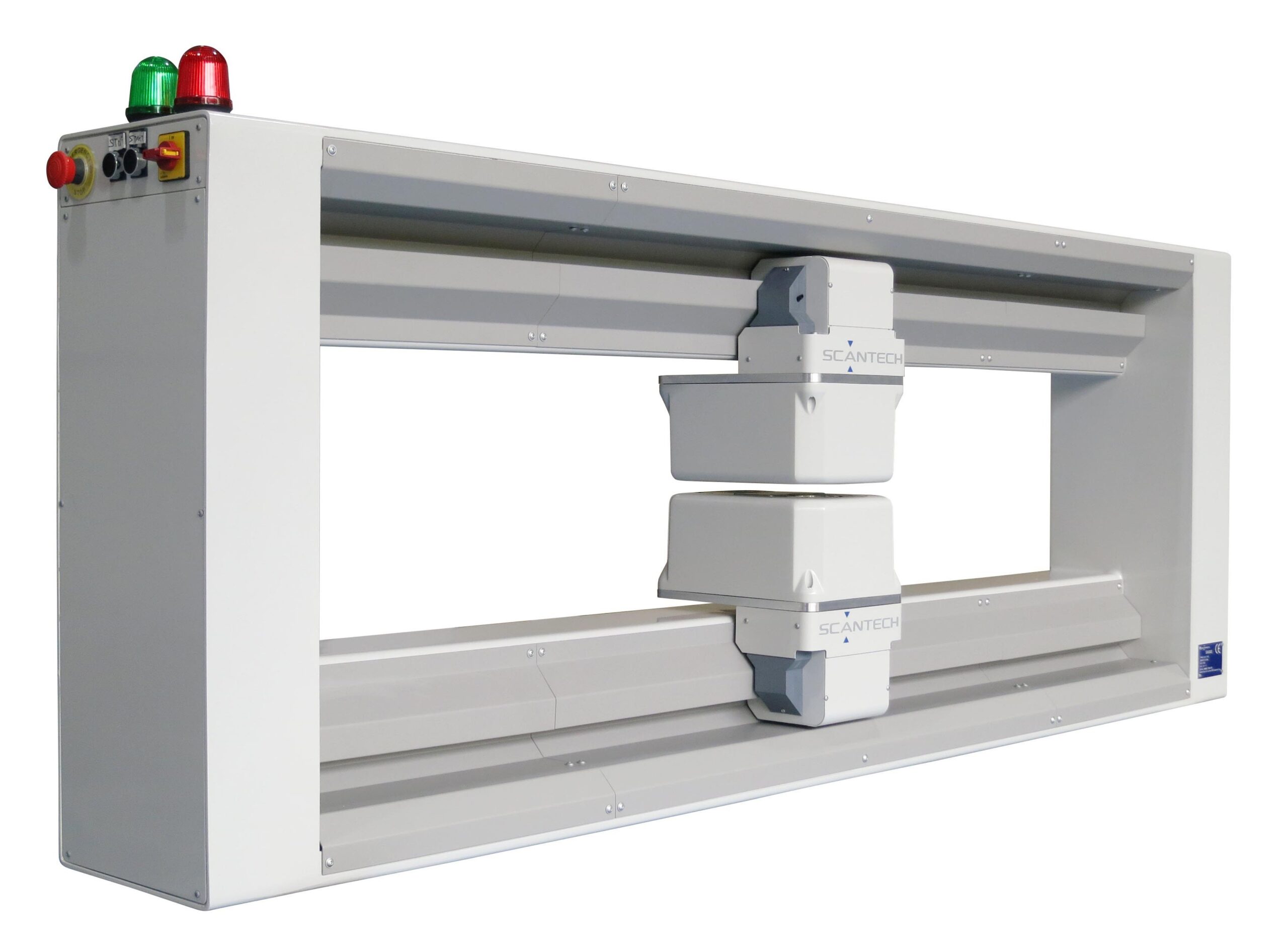

Why Scantech low-energy X-ray is a strong film and sheet platform
Scantech applies low-energy X-ray transmission to film and sheet measurement and offers scanner frames, HMIs, profile controls, and process-integration options. On cast film and sheet, Scantech lists thickness, selected barrier-layer, density, and filler measurements along with automatic mapping, APC, bolt control, power and temperature control, a melt-flow model, and machine-direction control.[8] On blown film, Scantech places the scanner at the layflat and uses deconvolution and mapping algorithms to resolve the double layer back to the die or air ring.[7]
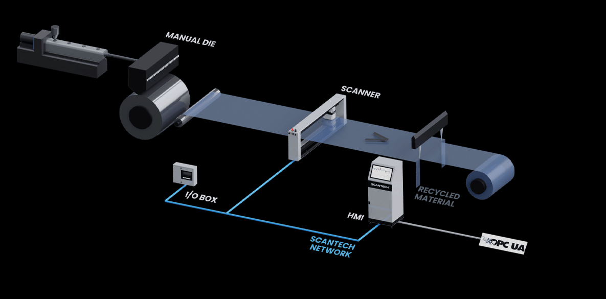
Scantech measures the profile; Addex can change the cooling around the bubble
Cast film commonly corrects CD profile with die bolts or thermal actuators. Blown film often needs a high-resolution cooling correction around the circumference, accurate mapping from the layflat back to the bubble, and stable internal bubble control.
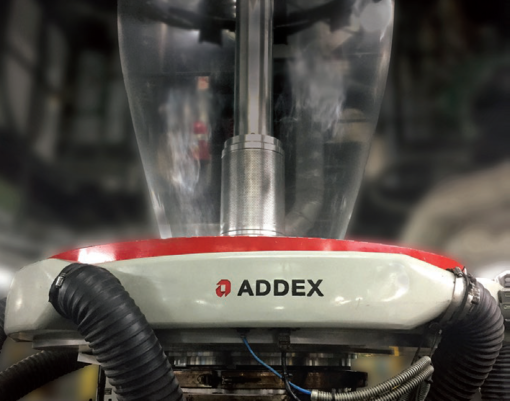

Addex MGC provides many individually adjustable air vanes for manual local cooling correction. Addex publishes application-dependent reductions and positions MGC as a lower-cost manual profile path.[11]
EGC automates the cooling correction and maps measured profile data with line position. Addex publishes greater than 50% gauge-variation reduction for applicable systems, which should be treated as a manufacturer result, not a universal guarantee.[10]
DIBC uses digital sensing and control to stabilize bubble size and layflat. It addresses bubble and width behavior rather than ingredient ratio or total-film thickness by itself.[12]
Use the Blown Film Cooling and Control Selector when the problem involves cooling capacity, bubble stability, layflat, MGC, EGC, DIBC, or a coordinated scanner and air-ring retrofit.
Start with the film symptom before selecting equipment
Select the closest condition. The response identifies the process layer to investigate first and the represented equipment that may support the correction.
Gauge looks stable, but color, seal, or product properties drift
Treat this as a formulation, layer-ratio, material identity, or residence-time problem before changing the die profile. Total thickness can remain stable while the composition inside that thickness changes.
Ingredient flow by component, feeder refill events, wrong source connection, reclaim identity, drying, extruder rate by layer, and transition holdup.
ABS continuous gravimetric blending, suitable feeder styles, SMART routing, and recipe or throughput controls.
A Scantech scanner can confirm total profile, but it cannot identify every recipe or layer error without the appropriate material-specific measurement.
Build a preliminary film process-control architecture
This selector chooses the process layer that should lead the review. It does not replace line drawings, recipes, rate data, film samples, profile trends, or factory application engineering.
Estimate two losses that blending and gauging may help address
This calculator keeps average-gauge overbuild and additive overfeed separate. It does not assume that either amount is fully recoverable, and it does not add them into one savings claim.
A practical implementation sequence
Recipe percentages, component mass flow, total throughput, average thickness, CD profile, MD trend, layflat, bubble size, or finished properties.
Collect synchronized blender, pressure, speed, scanner, roll, laboratory, scrap, and changeover data before changing several variables.
Validate load cells, feeders, refills, scanner calibration, web path, profile mapping, product recipe, and laboratory correlation.
Identify what can physically change the loss: feeder rate, extruder rate, line speed, die bolts, air-ring zones, IBC, or another control point.
Use product properties, roll reports, capability, customer requirements, and controlled trials before reducing safety margin.
Assuming continuous blending automatically guarantees uniform film
Continuous metering improves visibility and control of ingredient mass flow. It does not correct poor feeder selection, refill disturbance, material segregation after the blender, extruder instability, die distribution, cooling, or winding.
Calling every batch blender inferior
A properly applied batch system can be adequate for many stable processes. Continuous blending earns its premium where direct component flow, low-rate dosing, rate changes, multilayer coordination, reclaim, or changeover performance materially affects the line.
Sizing a blender from total throughput only
Every component has its own minimum and maximum rate. A low-percentage powder, high-rate reclaim stream, or difficult-flowing flake can determine feeder and frame selection even when total line rate looks modest.
Using total thickness as proof of every layer ratio
A total-thickness scanner can show a stable web while individual coextrusion layers move in opposite directions. Layer-specific measurement depends on material contrast, calibration, and the selected Scantech configuration.
Buying a scanner without a response plan
Measurement can reduce reaction time and provide traceability even without automatic control, but the business case is strongest when the operator or actuator has clear authority, timing, limits, and invalid-data behavior.
Mapping blown-film profile to the wrong bubble location
Rotating dies, oscillating hauloff, nip speed, transport delay, double-layer deconvolution, and air-ring zone position must agree. A correction to the wrong zone can increase variation.
Claiming higher Cpk before proving stability
Capability is calculated from process data after stability, sampling, distribution, and measurement-system assumptions are reviewed. New equipment may reduce variation, but the resulting Cpk or Ppk must be demonstrated.
Adding material savings that overlap
Gauge overbuild, additive overfeed, startup scrap, and off-spec roll mass can describe some of the same pounds. Build separate loss buckets and reconcile them to plant material usage before totaling a business case.
Ignoring winding after the profile improves
A good thickness profile can still wind poorly because of tension, bagginess, guiding, slit-zone behavior, surface treatment, or roll hardness. Keep web handling as a separate diagnostic layer.
Film blending and gauging project checklist
- Film process and structureBlown, cast, sheet, MDO, biax, coating, mono or multilayer, layer count, polymers, fillers, additives, and target properties.
- Production ratesMinimum, normal, and maximum total rate plus each extruder or layer rate, line speed, width, gauge, and annual hours.
- Every ingredient rateVirgin, regrind, reclaim, color, slip, antiblock, processing aid, tie, barrier, filler, powder, and low-percentage additives.
- Current blending methodBatch, continuous, volumetric, manual, feeder models, load cells, refill method, mixing, surge, calibration, alarms, and controls.
- Material handlingSources, drying, conveying, receivers, routing, pipe sizes, distances, dust, segregation, contamination, and available floor or mezzanine space.
- Thickness requirementTarget, tolerance, average, minimum, CD profile, MD trend, basis weight, density, filler, layer, edge, and roll-report needs.
- Process actuatorsManual or automatic die bolts, thermal bolts, extruder speed, line speed, Addex air ring, EGC, MGC, IBC, rotating die, and hauloff.
- Current loss dataGauge giveaway, additive overfeed, purge, startup scrap, changeover time, off-spec rolls, rework, downtime, and customer complaints.
- Integration requirementsPLC, OPC-UA, recipes, work orders, data historian, roll reports, alarms, remote support, plant network, and cybersecurity rules.
- Samples and trendsRepresentative resin, film, roll maps, good and bad recipes, lab results, pressure trends, photos, line drawings, and known defect examples.
Related Gauge Advisor resources
Film blending and thickness-control FAQs
Is continuous gravimetric blending always more accurate than batch blending?
No. Continuous loss-in-weight blending provides direct component mass-flow control and better short-term visibility, but actual performance depends on load cells, feeder selection, refill control, vibration, material flow, rate range, installation, and maintenance. A validated batch system can be appropriate for stable, less demanding recipes.
What is the biggest advantage of continuous blending on a film line?
The most important advantage is component-level mass-flow control while the line runs. That is valuable when the recipe contains low-rate additives, reclaim, several layers, frequent rate changes, or expensive materials whose short-term ratio matters.
Does a continuous blender eliminate the need for mixing?
ABS designs SIMPLICITY for simultaneous metering without a separate mechanical mixer. That does not mean the complete material path is irrelevant. Feeders, discharge, piping, surge volume, extruder intake, and residence time still affect what reaches the screw.
Can a thickness gauge detect a wrong recipe?
Usually not by total thickness alone. A wrong recipe can produce the correct total gauge while changing density, seal, color, barrier, stiffness, or another property. Selected Scantech configurations can measure density, filler, or barrier response when the materials and calibration support it.
What is the difference between CD and MD thickness control?
CD control changes the profile across the width using die or cooling actuators. MD control changes the average over time through total output, line speed, or another machine-direction variable. The loops should not fight each other.
Why measure blown film at the layflat?
Layflat scanning provides a stable web path after the bubble collapses. Scantech uses algorithms to deconvolve the two film layers and map the profile back to the die or air ring. Correct mapping and transport delay are essential.
When should Addex be included with Scantech?
Include Addex when the application is blown film and the plant needs a physical cooling or bubble-control actuator. Scantech provides the profile measurement; Addex MGC or EGC changes external cooling, while DIBC addresses internal bubble and layflat stability.
Can these systems increase Cpk?
They may reduce assignable variation or improve centering when correctly applied, but Cpk must be calculated from a stable process and valid measurement data. Do not use a manufacturer specification or one trial as proof of process capability.
Should blending or gauging be upgraded first?
Upgrade the layer that is creating the verified loss. If composition or mass flow is unstable, begin with material control. If recipe data is stable but profile is poor, begin with measurement and the appropriate die or cooling actuator. Many projects need both, but not necessarily at the same time.
What information is needed for a preliminary quote?
Provide the film process, structure, ingredients and rates, throughput, width, thickness range, current blender, current gauge, line drawings, control actuators, changeover frequency, loss data, integration requirements, and representative trends or samples.
References and source notes
The references remain collapsible so the commercial article is easy to scan. They open automatically when printing.
Open technical references and source notes16 sources
Gauge Advisor is an authorized Advanced Blending Solutions, Scantech, and Addex sales and applications support partner. Manufacturer sources are used for current product architecture and published capabilities. Academic control research, a resin-supplier processing guide, NIST, and ASTM provide noncompetitive process and measurement context. No competitive blending, gauging, or air-ring equipment manufacturers are cited.
- Advanced Blending Solutions, SIMPLICITY Continuous Blenders. Simultaneous metering, feeder identification, recipe management, feeder options, discharge options, and manufacturer-estimated model rates.
- Advanced Blending Solutions, SL Gravimetric Blender. Continuous loss-in-weight design, integral weighed downcomers, integrated vacuum sequence option, and manufacturer-estimated SL family rates.
- Advanced Blending Solutions, Chameleon 2.0 Auto-Cleanout Blender. Automated component draining, vacuum and compressed-air cleanout, published operating benefits, and new-blender-only limitation.
- Advanced Blending Solutions, Simplicity Control Solutions. Allen-Bradley and Beckhoff options, scalable PC and PLC controls, extrusion-throughput control, vacuum sequencing, and integration.
- Advanced Blending Solutions, SMART Material Distribution. Recipe connection verification and complex coextrusion or centralized routing applications.
- Previdi et al., Control System Design for a Continuous Gravimetric Blender, IFAC World Congress, 2011. Dedicated component meters, load-cell flow estimation, mass-flow regulation, recipe-ratio control, and coordination with extrusion demand.
- Scantech, Blown Film Measurement Systems. Layflat X-ray measurement, double-layer deconvolution, profile mapping, and control-response context.
- Scantech, Cast Film Automatic Die Controls. Thickness, selected barrier, density and filler outputs, auto mapping, APC, bolt control, melt-flow model, and machine-direction control.
- Scantech, Extrusion Industry Online Measurement and Control. Manufacturer overview of low-energy X-ray, scanners, film applications, reports, and control architectures.
- Addex, External Gauge Control. Profile mapping, Generation 3 controller, and integration with blown-film control modules. Manufacturer performance results are application-dependent.
- Addex, Manual Gauge Control Air Rings. High-resolution manual air-vane adjustment and manufacturer-published profile-improvement examples.
- Addex, Digital Internal Bubble Cooling. Digital sensing, bubble and layflat control, and integration with Addex or other control systems.
- LyondellBasell, A Guide to Polyolefin Film Extrusion. Material handling, blending, coextrusion, dies, cooling, gauge measurement, controls, winding, and film-property context.
- NIST, What Is Process Capability?. Stable-process requirement and definitions for Cp and Cpk.
- ASTM D6988-21, Standard Guide for Determination of Thickness of Plastic Film Test Specimens. Laboratory film-thickness guidance and stated scope limitations.
- Advanced Blending Solutions, Remote Support, with After-Sales Support. Published remote diagnostics, 24-hour service call path, maintenance, repairs, technical support, and training resources.
Connect the material recipe to the film profile
Gauge Advisor is the authorized Advanced Blending Solutions, Scantech, and Addex sales and applications support partner. I help film and sheet manufacturers evaluate, select, quote, integrate, and support continuous gravimetric blending, resin handling, online thickness gauging, automatic profile control, and blown-film cooling and bubble-control equipment.
Gauge Advisor supports equipment selection and integration for the manufacturers represented here; independent process consulting is not offered. Send the film structure, ingredient rates, throughput, current blender, gauge profile, line drawings, control actuators, and representative production data when available. I will respond within one business day, often within a few hours.
- Continuous versus batch blender application review
- ABS feeder, routing, conveying, drying, and control scope
- Scantech scanner and measurement-output selection
- Cast-film die or machine-direction control review
- Addex blown-film MGC, EGC, DIBC, and cooling review
- Quotations, integration, sample coordination, and support