Updated October 9, 2026
Choosing a gauging system for film or sheet extrusion is not the same as choosing a sensor. The project has to define the physical property, the process location, the scanner geometry, the calibration model, the way the profile will be interpreted, and the action that should follow. A strong sensor can still become a weak system when it measures the wrong property, sits on an unstable passline, uses incomplete product data, or feeds a control loop that cannot correct the variation.
Select a film or sheet gauge and request pricing
Start with the material, working range and line layout. Gauge Advisor can help configure a Scantech measurement system around the property you need to control.
Define the material and layers, thickness or basis-weight range, and reference method.
Match the frame to the web width, installation space and measurement location.
Decide whether the project needs profile reporting, process feedback or automatic control.
Start with three details. These are optional; share what you know and we can clarify the rest.
Continue to the contact form to add your contact details and send your request. Gauge Advisor provides authorized Scantech sales and applications support.
Connected process path: Select the gauge in the context of the process that creates the profile—resin feeding, melt delivery, line mechanics, and the available control actuator.
Related next steps: continuous gravimetric blenders, throughput-control weigh hoppers, film and sheet melt delivery, extrusion pressure stability, and film and sheet measurement systems.
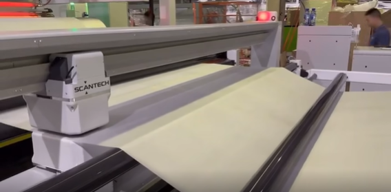
What does the plant need the gauging system to prove?
“Thickness” is often used as a catch-all. Select the output that actually controls the drawing, recipe, customer report, or process decision. The correct sensor and calibration can change when the same web is described in microns, grams per square meter, density, coating add-on, filler percentage, or profile uniformity.
Physical or calibrated thickness
First decide whether the project needs direct geometric caliper or a calibrated thickness inferred from transmission. X-ray can be an excellent production thickness system when material composition and density are represented in the calibration. Laser geometry becomes important when true surface-to-surface distance must be separated from mass per area.
Scantech low-energy X-ray for broad online profile measurement; add laser when direct caliper or density is required.
Minimum, nominal, and maximum product; density; fillers; layers; color; recycled content; temperature; accepted laboratory method.
An attenuation-derived thickness is not automatically identical to a contact micrometer result on every material, surface, or sampling plan.
Five linked decisions determine whether the installation creates useful data
Sensor selection gets the most attention, but the scanner, web presentation, software, and process response often determine whether the result is trusted and used.
Define the web construction, physical property, units, tolerances, normal variation, and accepted reference method.
Choose attenuation, geometry, optical absorption, vision, or a combined signal that remains tied to the true requirement.
Provide width, edge coverage, stable web path, access, guarding, environment, utilities, and practical maintenance clearance.
Build recipes, calibration, profiles, edge rules, roll reports, alarms, process tags, and a map from measured position to actuator position.
Define who responds, which actuator changes the result, the transport delay, limits, invalid-data behavior, and verification method.
Keep the direct signal separate from the reported value
X-ray transmission directly detects photon attenuation through the web. The attenuation depends on photon energy and material composition.[9]
Mass per unit area is obtained from the calibrated attenuation relationship for the application and product family.
Thickness can be calculated or calibrated when density and composition are sufficiently controlled or modeled.
Density requires both mass per area and geometric thickness. One signal alone cannot separate the two variables.
Machine direction and cross direction are different problems
A scanning gauge produces a profile across the width and a trend along the production length. The distinction matters because the likely causes and corrective devices are different. Sheet and film control research treats machine-direction and cross-direction behavior as separate control objectives, with transport delay, mapping, actuator interactions, and process constraints affecting achievable performance.[13]
Cross direction, CD
The scanner traverses the usable width and builds a profile. Persistent center-heavy, edge-heavy, lane, streak, or polar patterns may point toward die distribution, cooling, stretching, coating flow, mapping, or a fixed machine-position disturbance.
- Typical action: die bolts, thermal zones, air-ring zones, coating-head adjustment, or maintenance.
- Key requirement: accurate mapping from scanner position to the physical actuator.
- Common trap: changing average output when the real problem is local minimum thickness.
Machine direction, MD
The system follows average thickness or selected profile zones over time. Cycles and steps may correlate with feed rate, extruder pressure, screen changes, line speed, chill-roll conditions, MDO draw, or product transitions.
- Typical action: extruder speed, line speed, melt pump, coating flow, or operator correction.
- Key requirement: known transport delay from actuator to scanner.
- Common trap: heavy filtering that hides short changes and slows response.
The same sensor can require a different system on each extrusion line
Select the process that most closely matches the project. The result identifies the likely measurement stack, control path, and application boundary.
Cast film and flat sheet: profile measurement can connect directly to the die
A stable flat passline allows the scanner to measure the single-layer web across its full usable width. Scantech offers thickness, density, filler, barrier, visual-inspection, automatic mapping, machine-direction control, and automatic profile-control paths depending on the line.[3]
Low-energy X-ray scanner, HMI, recipes, roll reports, and profile mapping. Add laser or vision where the separate property requires it.
Automatic die bolts or thermal actuators for CD; line or extrusion controls for MD after transport delay and loop authority are defined.
Web width, edge trim, die width, bolt pitch, passline, flutter, thickness range, filler, multilayer structure, startup changes, and available straight span.
Match the physical signal to the required property
This is a concise project-selection comparison. For a deeper treatment of each sensor type, use the Engineer’s Guide to Web Gauging Technology.
| Technology | Direct physical signal | Strongest film and sheet roles | Important limitations and project checks |
|---|---|---|---|
Low-energy X-ray Primary Scantech path | Photon attenuation through the moving web. | Basis weight, calibrated thickness, profile, filled film, multilayer applications, coating add-on, density when paired with geometry, roll records, and automatic control. | Composition, density, filler, pigment, PCR, layers, air gap, calibration samples, web path, attenuation range, and recipe changes must be represented. |
Laser or optical geometry | Surface position, displacement, shadow, or optical focus. | True caliper, very thick sheet, width, edge, surface geometry, and density calculation when paired with a mass signal. | Flutter, transparency, reflectivity, roughness, embossing, angle, passline, reference surface, and opposing-head alignment. |
Infrared, NIR, or microwave | Wavelength- or frequency-specific absorption, reflection, or dielectric response. | Moisture, solvent, selected chemistry, barrier response, organic coating, or constituent measurement when the material has a useful signature. | Product-specific calibration, color, gloss, temperature, formulation, cure state, substrate interference, and changing optical path. |
Visual inspection | Image contrast, color, shape, texture, or mapped defect appearance. | Holes, contamination, streaks, edge defects, gels, appearance defects, and reviewable defect records. | Lighting, color, transparency, surface texture, web motion, defect definition, false alarms, and the fact that appearance is not thickness. |
Multi-sensor or differential | Two or more synchronized signals or two process locations. | Density, porosity, coating deduction, pre/post stretching comparison, layer or constituent information, and gauge plus defect inspection. | Time and position registration, same-spot logic, separate calibrations, web draw, transport delay, and higher integration effort. |
| Attenuation or backscatter from a sealed radioactive source. | Existing installed-base applications with a validated method and an established radiation-safety program. | Licensing or registration, source accountability, leak tests, decay, relocation, shipping, disposal, and end-of-life planning.[12] |
Build a preliminary film and sheet gauging architecture
The selector identifies a strong starting path. Final equipment selection still requires drawings, samples, scanner-width review, attenuation calculations, calibration planning, process-control details, and Scantech factory confirmation.
Estimate how far the web travels while one full profile is built
A scanner may take many fast point measurements, but one complete cross-web profile still requires travel across the selected scan width. This calculator converts the planning profile interval into machine-direction spacing and estimated roll coverage.
Planning limitations: The calculation assumes constant speed and a constant full-profile interval. Actual systems may scan bidirectionally, use dynamic edge limits, apply filtering, pause, park, or build control profiles differently. Confirm the quoted profile time, usable width, edge treatment, and control update logic.
Why the scanner frame, software, control package, and support path matter as much as the sensor
Scantech’s extrusion platform covers cast film and sheet, blown film, MDO, biax film, extrusion coating, and foam. Current manufacturer literature combines low-energy X-ray with laser, infrared, microwave, and visual-inspection options, along with scanner frames, HMIs, automatic mapping, machine-direction control, profile control, die-bolt control, reporting, training, support, and spare parts.[1][2]
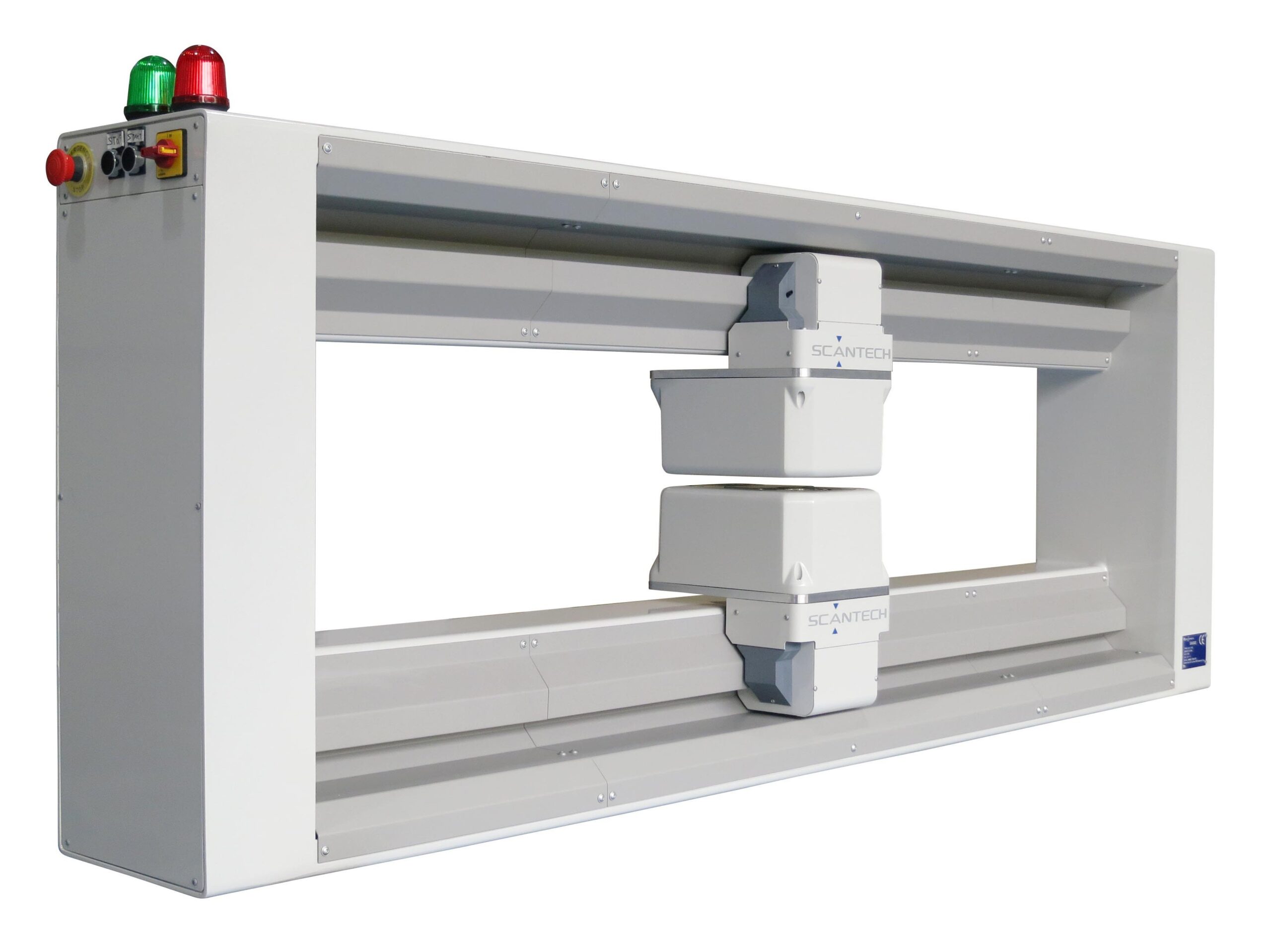
Match the frame to the actual passline
A compact scanner can fit lines where straight web length and access are limited, but the quotation still needs usable web width, frame opening, scanner orientation, edge travel, web support, guarding, and service clearance.
- Do not size from nominal product width alone
- Include maximum deckle and edge trim
- Provide layout drawings and installation photos
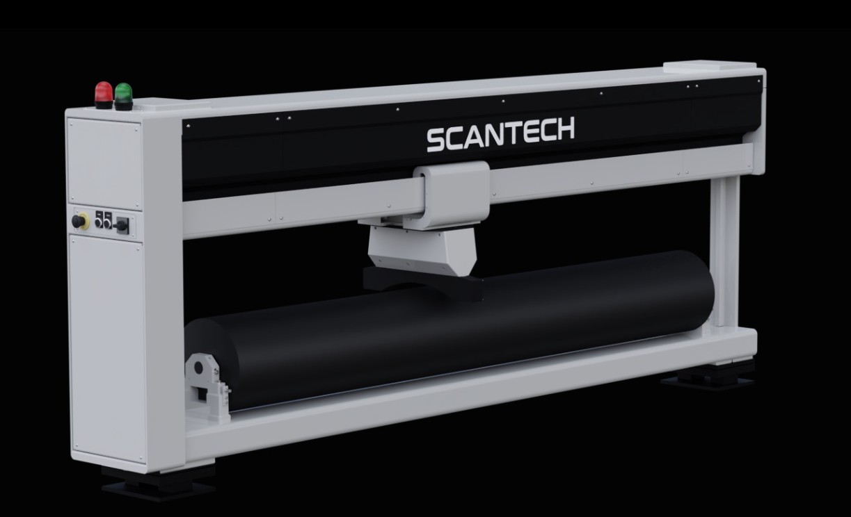
Frame mechanics affect profile quality
Very wide, hot, fast, or high-load applications require a scanner architecture that maintains alignment and repeatable travel across the complete measurement span.
- Review stiffness, thermal environment, vibration, and foundation
- Plan sensor parking, calibration, and maintenance access
- Confirm full-profile time at the quoted width

The useful output is more than one live number
Profiles, MD trends, roll reports, recipes, alarms, minimum and maximum values, process tags, and control status turn the sensor into an operating and quality tool.
- Define roll, lot, recipe, and product identifiers
- Agree on edge exclusions and valid data rules
- Plan export, PLC, OPC UA, historian, or MES requirements
Published flat-web frame-family starting points
Scantech publishes ULO3 as a compact starting family for cast film, MDO film, and extrusion-coating applications. The final opening, sensor package, orientation, and usable width still require application review.
Scantech publishes HF3 for wide cast-film, sheet, and foam applications. Frame stiffness, thermal environment, scanner travel, foundation, and profile time become increasingly important as width grows.
Scantech publishes this very-wide cast-film path with visual-inspection capability. It should not be selected from nominal width alone, and it is not the model-selection table for a blown-film layflat system.

Recipe selection, profile display, alarms, edge rules, control status, calibration, and report access should fit the plant’s real workflow.
List every PLC, die, speed command, melt pump, encoder, winder, line signal, historian, and protocol before the control scope is frozen.
Provide representative production samples and the accepted laboratory method. ASTM D6988 notes that film-thickness procedures may serve different purposes and may not agree exactly.[10]
Gauge Advisor supports application selection and project coordination, while Scantech publishes training, support, spare-parts, and regional service resources.
The information a supplier needs before selecting the sensor and scanner
A clear data package can prevent the most common sizing, calibration, installation, and control errors. Do not wait until after the quotation to identify a variable filler level, a second product edge, a vertical passline, or an unavailable control signal.
- Process and productCast film, sheet, blown film, MDO, biax, foam, extrusion coating, lamination, product use, and customer requirement.
- Complete material structureEvery polymer layer, tie layer, barrier, coating, adhesive, filler, pigment, ink, foil, substrate, and expected density.
- Production rangeMinimum, nominal, and maximum thickness or basis weight, startup range, grade changes, and expected extremes.
- Variability and recycled contentPCR, regrind, reclaim, masterbatch, CaCO3, TiO2, BaSO4, changing suppliers, moisture, and lot-to-lot composition.
- Web and scanner widthMinimum and maximum product width, deckle, trim, winder width, edge exclusions, and required measurement beyond saleable width.
- Speed and profile timingNormal and maximum speed, acceleration, startup duration, roll length, desired full-profile time, and shortest process event.
- Installation geometryHorizontal or vertical passline, two-sided access, straight span, scanner opening, web wrap, support rolls, guarding, and service clearance.
- EnvironmentWeb temperature, ambient heat, enclosure temperature, static, dust, fumes, moisture, vibration, washdown, hazardous area, and utilities.
- Web presentationFlutter, wrinkles, tension, guiding, edge wander, bow, sag, embossing, roughness, transparency, gloss, and intentional texture.
- Reference method and samplesAccepted laboratory procedure, calibration samples, good and bad rolls, full product range, and any current online-to-lab disagreement.
- Data and reportingHMI location, recipes, roll reports, statistics, CSV, OPC UA, PLC, SCADA, MES, historian, user permissions, and record retention.
- Control scopeManual response, MD speed or output, automatic die bolts, air-ring control, coating flow, actuator count, mapping, transport delay, limits, and fail-safe behavior.
Common film and sheet gauging specification mistakes
Requesting “thickness” without defining the physical property
Physical caliper, mass per area, calibrated thickness, coating add-on, density, and one layer are different outputs. State the unit, specification, laboratory method, and process decision before selecting the sensor.
Choosing a sensor from the polymer name alone
PE, PP, PET, TPU, EVA, PVC, and other families can contain fillers, pigments, barrier layers, recycled content, foam, and coatings that materially change attenuation, density, optics, and calibration.
Using one calibration across changing filler, PCR, or density
A stable display does not prove a stable material model. Build the calibration set around actual grade, filler, recycled-content, density, and thickness variation, then define recipe and verification rules.
Sizing the frame from saleable web width only
The scanner may need to see edge trim, neck-in, startup width, maximum deckle, calibration position, parking position, and mechanical clearance beyond the final saleable product.
Ignoring web flutter, guiding, tension, and support
The gauge may be measuring a moving or tilted target rather than true product change. FMS guiding or tension equipment can be the right complementary path when the measurement location cannot present the web repeatably.
Assuming the online result must equal one laboratory reading
The online system averages a defined sensor footprint and moving sample, while laboratory methods use selected specimens, contact force, conditioning, and their own sampling rules. Establish correlation, bias, repeatability, and intended use rather than forcing one unexamined offset.
Buying control before defining the actuator and map
A scanner does not correct the process by itself. Identify the die bolt, thermal zone, air-ring zone, speed command, melt pump, coating flow, or other actuator, then define mapping, authority, delay, limits, interactions, startup transfer, and invalid-data behavior.
Using an MD correction for a CD profile problem
Changing total output or line speed can move the average while leaving a persistent thin lane. A CD problem requires a mapped profile actuator or physical process correction.
Ignoring the special logic required for blown film
A post-layflat scanner measures two collapsed walls. Polar reconstruction requires known die rotation or haul-off rotation or oscillation. Around-the-bubble measurement avoids the two-wall deconvolution but has different mechanical, bubble-stability, and sensor-placement requirements. Use the dedicated bubble-versus-layflat guide.
Treating service access and support as an afterthought
Plan scanner parking, calibration, sensor access, spare parts, software backup, remote access, training, ownership of PLC changes, and the response path before the system becomes production-critical.
Related Gauge Advisor film and sheet resources
Film and sheet gauging-system FAQs
What is the best thickness gauge for cast film or sheet extrusion?
Low-energy X-ray is a strong general starting point because it supports online profiles, roll records, and automatic control across many film and sheet products. The final architecture may add laser for direct caliper or density, vision for defects, or another sensor for composition. Material, range, web width, passline, and control scope still determine the final system.
Does an X-ray gauge measure thickness directly?
The direct signal is photon attenuation through the web. The system converts that signal through a calibration model into basis weight, thickness, filler, or another application-specific output. When density or composition changes, the relationship may require separate recipes, compensation, or a second sensor.
How do fillers and recycled materials affect the measurement?
Mineral fillers, pigments, PCR, regrind, and changing layer ratios can alter attenuation and density. Provide the normal and extreme formulations with representative samples. Do not assume that one virgin-resin calibration covers every recycled or filled grade.
When should laser be added to X-ray?
Add laser when the project needs direct surface-to-surface thickness, very thick sheet measurement, density or porosity derived from mass and caliper, edge or surface geometry, or a way to separate geometric change from mass change. Optical suitability still depends on flutter, reflectivity, transparency, roughness, and passline stability.
Why might an MDO or biax line need two scanners?
Measurement before and after stretching separates the incoming sheet profile from the final oriented-film profile. Scantech recommends a two-scanner architecture for many MDO applications because draw, shrinkage, edge behavior, and mapping can change through the stretch section.[4]
Can the gauging system control the die automatically?
Yes, when the line has a compatible actuator and the project defines mapping, bolt or zone pitch, transport delay, control authority, limits, interactions, and invalid-data behavior. Scantech publishes automatic mapping, machine-direction control, and automatic profile-control architectures for applicable lines. A scanner alone does not create the correction.
Can Scantech measure blown film after the layflat?
Yes. A post-layflat X-ray architecture measures the two collapsed walls and can reconstruct a polar profile when the process has known die rotation or haul-off rotation or oscillation. Without that motion, the scanner cannot uniquely assign the two-wall signal back to original bubble sectors for mapped polar control. Around-the-bubble Addex measurement remains a separate valid architecture.
Where should the scanner be installed?
Place it where the product is sufficiently stable and representative, the required web edges are visible, two-sided access and guarding are practical, temperature and contamination are acceptable, and the remaining transport delay still supports the intended operator or control action. The best location varies by process.
How should online and laboratory thickness be correlated?
Define the laboratory method, specimen location, conditioning, contact force, sample orientation, online sensor footprint, averaging, time or roll registration, and statistical acceptance. ASTM D6988 and ISO 4593 address film-thickness methods, but neither makes every online and offline result automatically interchangeable.[10][11]
What information is needed for a preliminary Scantech quotation?
Provide the process, complete material and layer structure, measurement output and units, minimum and maximum range, web and deckle width, line speed, scanner location, passline drawings, environment, lab method, product samples, HMI location, plant communications, and exact manual or automatic control scope.
References and source notes
The references are collapsible to keep the article readable. They open automatically when printing.
Open technical references and source notes15 sources
Gauge Advisor is the authorized Scantech sales and applications support partner. Scantech sources are used for current equipment architecture and manufacturer-published capabilities. NIST, ASTM, ISO, NRC, and peer-reviewed control literature provide neutral measurement, safety, laboratory-method, and process-control context. Addex and FMS are discussed only where cooling control, tension, or guiding is a separate complementary requirement. No competitive equipment manufacturer is cited.
- Scantech, Extrusion Industry Online Measurement and Control Brochure. Manufacturer overview of low-energy X-ray, laser, infrared, microwave, visual inspection, biax, blown, cast and sheet, MDO, extrusion coating, foam, scanners, controls, support, and spare-parts architecture.
- Scantech, Company Presentation. Current history, low-energy X-ray positioning, non-nucleonic technology strategy, multi-sensor development, support, training, and regional organization.
- Scantech, Cast Film Automatic Die, Controls, and Visual Inspection. Manufacturer-published thickness, density, filler, barrier, defect, mapping, machine-direction, and profile-control capabilities.
- Scantech, Online Measurement for Cast Film Production Lines FAQ. Process-variation, cast-film control, width, filler, and two-scanner MDO guidance. Manufacturer statements are application-dependent.
- Scantech, MDO Film Measurement and Control. Thickness, density, filler, barrier, defects, porosity, mapping, and control architecture.
- Scantech, Foam Measurement and Control. Basis-weight, thickness, density, defect, and control context for foam applications.
- Scantech, Coating Film Measurement. Coating and converting application architecture.
- Scantech, Very Thick Cast Film and Sheet Laser Measurement. Manufacturer laser-measurement and automatic-control path for thick material.
- NIST XCOM Photon Cross Sections Database. Reference data and calculation framework for photon interaction and attenuation in elements, compounds, and mixtures.
- ASTM D6988-21. Guide for determining plastic-film specimen thickness and important context that different thickness methods may serve different purposes and may not agree exactly.
- ISO 4593:1993. Mechanical-scanning method for plastic film and sheeting; confirmed current in 2025 and not suitable for embossed film or sheeting.
- U.S. NRC, NUREG-1556 Volume 4, Fixed Gauges. Licensing, radiation-safety, source-accountability, maintenance, transfer, and disposal guidance for fixed gauges using sealed radioactive materials.
- VanAntwerp, Featherstone, Braatz, and Ogunnaike, Cross-Directional Control of Sheet and Film Processes, Automatica, 2007. Peer-reviewed review of MD and CD control, scanning measurement, mapping, delay, actuator interactions, constraints, and process monitoring.
- Gauge Advisor, Engineer’s Guide to Web Gauging Technology. Detailed technology comparison, application matrix, profile interpretation, and measurement-method boundaries.
- Gauge Advisor, Blown Film Thickness Measurement: Bubble vs. Layflat Scanners. Detailed Addex and Scantech architecture comparison, motion requirement, two-wall deconvolution, control communication, and installation choices.
Build the gauging system around the product, passline, and process decision
Gauge Advisor is the authorized Scantech sales and applications support partner. I help film and sheet extruders evaluate, select, quote, integrate, and support Scantech low-energy X-ray, laser, multi-sensor, visual-inspection, scanner, HMI, reporting, and automatic-control systems.
Gauge Advisor supports equipment selection and integration for the manufacturers represented here; independent process consulting is not offered. For blown-film projects, I can also coordinate the measurement architecture with represented Addex cooling and bubble-control equipment when that is the correct control path.
Send the material structure, measurement range, web width, speed, layout, temperature, laboratory method, process-control scope, and representative samples when available. I will respond within one business day, often within a few hours.
- Sensor and scanner architecture review
- Material, range, and calibration planning
- Passline and installation review
- HMI, reporting, PLC, and OPC UA scope
- MD, CD, die, and blown-film control review
- Quotation and Scantech factory coordination